DURLON密封技术手册.Image.Marked
DULCOTrans 32 700 PVDF 或 PP 装配和操作说明书

筒泵DULCO ®Trans 32/700 PVDF 或 PP装配和操作说明书原版操作说明书 (2006/42/EG) / 目标群体:商用981984BA DTR 004 01/19 ZH整阅读使用说明书。
• 请勿丢弃说明书。
或操作失误而造成的损失,由运营商承担。
本的操作说明书可从我们的主页下载。
本文件使用中性意义上按照语法的男性方式来使文本更易读。
始终以相同的方式称呼女士和男士。
我们请女性读者理解文章中的这种简化。
请阅读补充说明。
信息说明书中给出了设备正确操作或易于您操作的重要信息。
警告提示警告提示详细描述了危险情况,请参阅 Ä 章节 2.1 “警告提示标识”第 7 页。
本文件中可能使用以下标识强调操作说明、参考、列表、结果以及其它相关内容:一般同等对待补充说明补充说明2目录目录1功能、稳定性和供货范围 (4)2安全说明章节 (7)2.1 警告提示标识 (7)2.2 用户资格 (8)2.3 按规定使用 (8)2.4 可能出现的滥用 (8)2.5 安全 (9)2.5.1 泵和电机的安全提示 (9)2.5.2 喷嘴的安全提示 (10)2.6 声压级 (10)3储存和运输 (11)3.1 运输 (11)3.2 包装的废弃处理 (11)4装配和调试 (12)4.1 泵的装配 (12)4.2 电机说明和过电流触发 (12)5操作 (13)6每次使用后的清洁 (15)7维修、故障和备件 (16)7.1 检查/维修 (16)7.2 故障排除 (18)7.3 DULCO®Trans 的备件 (18)7.3.1 DULCO®Trans 32/700 PP 备件组件 (18)7.3.2 DULCO®Trans 32/700 PVDF 的备件组件 (19)7.3.3 电机备件 (20)7.3.4 泵的备件 (22)7.3.5 喷嘴的备件 (24)7.3.6 配件 (25)8旧零部件处理 (26)9技术参数一览表 (27)9.1 技术数据,PP 规格 (27)9.2 技术数据,PVDF 规格 (28)9.3 功率图 (29)9.4 带有主要尺寸的比例图 (29)10欧共体/欧盟机械符合性声明 (30)11索引 (31)31 功能、稳定性和供货范围如需转移液体,这种筒泵是理想的解决方案。
达诺(Dorner)2200系列标准传动带接缝技术说明书

2200 SERIESSTANDARD BELTINGBELT SPLICINGPlastic Clipper**An optional plastic clipper splice is available for quick removal of belts or when conveyors are installed in tight spaces.Finger SpliceAll belts are available with a standard Thermoformed finger splice. This splice makes the belt continuous and is virtually undetectable. Splice bonding methods vary by belt type. Consultfactory for details.Metal Clipper**An optional metal clipper splice is also available for quick removal of belts or when conveyors are installed in tight spaces.** S ee belt charts for compatibility. Not for use with 2200 Series Nose Bar Transfers. Plastic and Metal Clippers are slightly thicker than base belt. Contact factory fordetails.V-GuidingStandard Belt Selection GuideStandard belt material is stocked at Dorner,B e l t T y p e - F i n g e r S p l i c eB e l t T y p e - P l a s t i cC l i p p e rB e l t T y p e - M e t a lC l i p p e rB e l t S p e c i f i c a t i o n sV -G u i d a b l e16 m m N o s e B a rB e l t T h i c k n e s sS u r f a c e M a t e r i a lM a x i m u m P a r t T e m p e r a t u r eC o e f f i c i e n t o f F r i c t i o nF D A A p p r o v e dA n t i -S t a t i cS t a t i c C o n d u c t i v eC h e m i c a l R e s i s t a n c eS p e c i a l C h a r a c t e r i s t i c s o r A p p l i c a t i o n s01A11A FDA Accumulation x 1.7 mm Urethane 100˚C Low x x Good Packaging, clean room and inspection02A22A General Purpose x 1.8 mm Urethane 100˚C Med x x Good Most versatile belt offering 03A33A FDA High Friction x 1.7 mm Urethane 100˚C High x x Good Packaging, clean room and inspection05A55A Accumulation x x1.2 mm Urethane 100˚C V-Low xx Good Accumulation of products 06A66A Electrically Conductive x 1.6 mm Urethane 80˚C V-Low x xGood Electronics Handling 08A88AHigh Friction x 2.1 mm PVC 70˚C V-High xPoor Conveys up to 35˚ inclines*09iDrive General Purposexx 1.5 mmUrethane100˚CHighxGoodLower No Load TorqueNote: See below for splice details. Plastic Clipper splice requires longer lead times. Clipper splice not available on Z-Frame Series Conveyors.Note: B elts with V-Guiding may have a slight high spot or rib on the top surface. This rib would run longitudinally along the center of the belt.Consult factory with applications for which this may cause interference.*Incline varies due to factors like dust, fluids and part material.2200 SERIESSPECIALTY BELTINGB e l t T y p e - F i n g e r S p l i c eB e l t T y p e - P l a s t i cC l i p p e rB e l t T y p e - M e t a lC l i p p e rB e l t S p e c i f i c a t i o n sV -G u i d e a b l e16 m m N o s e B a rB e l t T h i c k n e s sS u r f a c e M a t e r i a lM a x i m u m P a r t T e m p e r a t u r eC o e f f i c i e n t o f F r i c t i o nF D A A p p r o v e dA n t i -S t a t i cS t a t i c C o n d u c t i v eC h e m i c a l R e s i s t a n c eS p e c i a l C h a r a c t e r i s t i c s o r A p p l i c a t i o n s19Nose bar High friction x 0.7 mm Urethane 100˚C High x x Good Nose bar, high friction 50Heat Resistant 1.3 mm Silicone 180˚C Low xV-Good High temperature 53Translucent x0.5 mm Urethane 100˚C V-Low x GoodBack lit inspection54F44F FDA Sealed Edge**x 1.6 mm Urethane 80˚C Low x x Good Packaging, clean room and inspection 55F55F FDA Sealed Edge**x 1.6 mm Urethane 80˚C High xx Good Packaging, clean room and inspection 566F Cut Resistant x 2.1 mm Urethane 100˚C Med.x Good Oily product release, metal stamping 577F Cut Resistant x 2.5 mm Nitrile 80˚C Med.x Poor Felt-like, dry metal stamping, glassand ceramic588F Cut Resistant x 1.6 mm Urethane 90˚C Low x Good Surface gold colored 59F99FColor Contrasting x 1.6 mmPVC 70˚C Med.xPoor Black colored, hides overspray fromink jet60G00G Color Contrasting x x 1.3 mm Urethane 100˚C Low x xGood Green colored 61G11GColor Contrasting x x1.3 mm Urethane 100˚C Low xGoodBlue colored633G Electrically Conductive x 1.2 mm Urethane 80˚C Low x x Good Static conductive, electronics handling 644G High Friction x 4.4 mm PVC 80˚C V-High x Poor Dark Green colored, rough top surface, product cushioning, incline/decline apps 666GChemical Resistant x 1.7 mm Polyester 100˚C Med.x xV-Good Good cut resistance, metal stamping apps 67Low Friction Cleated (Do not use with Z-Frame)x1.6 mmPolyester100˚Cn/axGoodExcellent product release, consult factory for part number and how tospecify low friction 68G8FDA Encased**x 1.5 mm Urethane 80˚C Low x x Good Urethane enclosed for added sanitaryprotection 69G9FDA Encased**x 2.2 mm Urethane 80˚C Med.x xGood Urethane enclosed for added sanitaryprotection71FDA High Release x 1.8 mm Urethane 100˚C Low x GoodHigh release cover 72Nose barxx 1.2 mm Urethane 100˚C Med.x x Good 16 mm Nose bar, medium friction73Nose bar Low friction x 0.9 mm Urethane 100˚C Low xx Good Nose bar, low friction 75Black Urethane x 1.5 mm Urethane 80˚C Low x Good 76Black Nose bar x x1.2 mm Urethane 80˚C Med.x Good Black Color, 5/16" nose bar 77High Friction, green x2.2 mm Urethane 100˚C High xGood Green color, high friction, urethane, grooved 78Chemical, Polyolefin, HF 1.4 mm Polyolefin 60˚C High x V-GoodChemical resistant, food grade 79Chemical, Polyolefin, LF 1.3 mm Polyolefin 60˚C Med.x xV-Good Chemical resistant, food grade 80High Friction, silicone x x 1 mm Silicone 80˚C High x Good Silicone material, high friction 81Low Friction, siliconex x1 mmSilicone100˚CMed.xGoodSilicone material, low to medium frictionNote: Clipper Splices not available on Z-Frame Series Conveyors.Note: C onveyors wider than 1,016 mm require V-Guide belt trackingNote: B elts with V-Guiding may have a slight high spot or rib on the top surface. This rib would run longitudinallyalong the center of the belt. Consult factory with applications for which this may cause interference. ** Not available in 51 mm widthsCleat Type Base Belt Belt Thickness Surface Material Color Coefficient of Friction V-GuidableMaximum Part Temperature FDA Approved Chemical Resistance K, L, B, E G-3-ST 2 mm PVC Green Medium No 80º C No Poor K, L, M, B, E, N, P , RG-3-ST-W1.3 mmUrethaneWhiteMediumYes90º CYesGood• M inimum cleat spacing = 50 mmCleat Selection could impact the minimum spacing.Contact the factory for details.*Maximum cleat spacing for 457 mm and wider conveyors = 500 mm **Maximum cleat spacing for 2134 mm and longer conveyors = 500 mm 457 mm and wider conveyors are limited to 2100 mm longNote: For Straight Cleated Conveyors = 20, 30, 35 mmFor LPZ Cleated Conveyors = 20, 30, 35, 40, 50 mmFor LPZ Sidewall Cleated Conveyors = 20, 30, 35 mm2200 SERIESCLEATED BELTINGTolerance ± 2 mmCleated Belt SpacingCleated Belt ProfilesK, N L, P M, R B E。
【精品】油封安装工艺手册
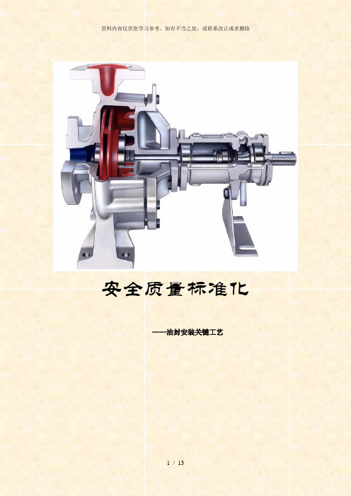
安全质量标准化——油封安装关键工艺骨架油封结构示意图名称各部位的作用①唇部唇端面(滑动面)唇端部是斜楔形状,在端部处按压轴表面,起到密封流体的作用。
②密封唇部密封唇是柔性弹性体,是对机械的振动及密封流体的压力变动的影响下仍可保持稳定的密封作用的设计,并起到保持唇部与轴表面接触状态,为稳定状态的作用。
另外弹簧可提高密封唇向轴的迫紧力,起维持此迫紧力的作用。
③防尘唇是没有与弹簧连接的副唇,起防止尘埃侵入的作用.防尘唇部④配合部配合部是油封在腔体孔内固定的同时,起防止流体从油封外周面与腔体内面的接触面间泄漏及侵入的作用。
另外金属骨架是当油封固定在腔体内时,起保持配合力的作用。
1、油封使用前保管要求1 不要打开原包装,注意包装是否损坏,装配前尽量把油封留在原包装里;2 避免日光直晒,也不要放置在高温热源附近,因为这会促使橡胶老化;3 油封不得随意散放,要注意防尘和防土,不要与化学品混放,确保使油封处在封闭或有盖状态;4 在运输和使用油封时,为防止油封变形和弹簧脱落,请不要给与过分冲击;5 油封不能用细绳捆扎,也不要挂在钉子或金属线上,这样会损伤密封唇;6 不得把油封放到潮湿的地方,这样会使金属部件生锈;7 不要将油封放在靠近电视和产生臭氧的地方;8 请不要用指甲或硬物摩擦唇口端部,以防损坏密封唇;2、轴、腔体的保护在装配前请不要使轴及腔体受到损伤,而引起泄漏,最好不要使精加工的轴与腔体碰撞到其他零件,请使用搬运夹具,如下例所示。
下图是搬运腔体用夹具,每一个腔体放入一个间隔中靠在壁上,不会损伤腔体孔,这种夹具的材质采用不会损伤金属的塑料(树脂).腔体的搬运夹具下图是轴用搬运夹具,使用塑料(树脂)罩防止轴损伤.轴的搬运夹具3、装配轴表面检查及主要参数确认表1:轴导入导角轴直径d1d1-d2轴直径d1d1—d2d 1≤10 1.5 50<d1≤70 4。
010<d1≤20 2。
0 70<d1≤95 4.520<d1≤30 2。
DRESSER-LAND-干气密封要求

DRY GAS SEAL SYSTEM DESIGN STANDARDS FOR CENTRIFUGALCOMPRESSOR APPLICATIONSJohn StahleyDresser-Rand, Turbo Products, Olean, NY, USAThis paper will propose a set of gas seal support system design standards for process gas centrifugal compressors on the basis of safety, reliability, and economics.ABSTRACTDry gas seals have been applied in process gas centrifugal compressors for over 20 years. Over 80 percent of centrifugal gas compressors manufactured today are equipped with dry gas seals.Despite the twenty-year trend of increasing dry gas seal applications, an industry accepted standard for gas seal support system design does not exist. The American Petroleum Institute (API) has only recently addressed gas seal system design in its Standard 614 (1999). This paper will propose a set of gas seal system design standards for process gas centrifugal compressors on the basis of safety, reliability, and economics.This paper will present the philosophy of one centrifugal compressor and dry gas seal original equipment manufacturer (OEM) in regards to gas seal system design standards. These standards are based on over twenty years of experience in the area of gas seal system design, drawing from actual field experience of thousands of compressors. The reader shall recognize, however, that numerous gas seal system design philosophies can be applied to achieve the same system objectives.INTRODUCTIONDry Gas SealsDry gas seals are available in a variety of configurations, but the "tandem" style seal (Fig. 1) is typically applied in process gas service and is the basis for this paper. Other types of gas seals (such as double opposed) are not considered. Tandem seals consist of a primary seal and a secondary seal, contained within a single cartridge. During normal operation, the primary seal absorbs the total pressure drop to the user's vent system, and the secondary seal serves as a backup should the primary seal fail.Dry gas seals are basically mechanical face seals, consisting of a mating (rotating) ring and a primary (stationary) ring (Fig. 2). During operation, grooves in the mating ring (Fig. 3) generate a fluid-dynamic force causing the primary ring to separate from the mating ring creating a "running gap" between the two rings. Inboard of the dry gas seal is the inner labyrinth seal, which separates the process gas from the gas seal. A sealing gas is injected between the inner labyrinth seal and the gas seal, providing the working fluid for the running gap and the seal between the atmosphere or flare system and the compressor internal process gas.Barrier SealsOutboard of the dry gas seal is a barrier seal, which separates the gas seal from the compressor shaft bearings (Fig. 1). A separation gas (typically nitrogen or air) is injected into the barrier seals. The primary function of the barrier seal is the prevention of lube oil migration into the gas seal. The barrier seal also serves as the last defense in the event of a catastrophic failure of the primary and secondary gas seal. Traditional labyrinth seals or segmented carbon ring seals are used in most barrier seal applications today. Segmented carbon ring barrier seals offer the advantage of substantially lower separation gas flow requirements due to the larger shaft clearance associated with labyrinth seals. The author has previously presented a more detailed comparison of segmented carbon ring versus labyrinth barrier seals (Stahley, 2001).Gas Seal Support SystemsThe use of dry gas seals requires a support system, which is normally supplied by the centrifugal compressor OEM mounted adjacent to the compressor. The purpose of the gas seal system is as follows:·To provide clean, dry sealing gas to the faces of the dry gas seals.·To provide clean, dry separation gas to the barrier seals.·To monitor the "health" of the dry gas seals and barrier seals.SEAL GAS SUPPLYSourceThe end user must provide a source of seal gas supply to the compressor OEM's gas seal system. The seal gas source must be available at sufficient pressure to cover the entire operating range of the compressor including transient conditions such as startup, shutdown, or idle, and all static conditions. The seal gas should be at least 50 psi above the required sealing pressure at the customer connection point on the gas seal system in order to allow adequate regulation of the seal gas. If the primary source of seal gas does not meet this requirement, an alternate gas source or gas pressure boosting equipment will be required. It is very common in the industry to source the seal gas directly from the compressor discharge. The author has previouslydiscussed various implications of this approach (Stahley,2001).Another concern is the quality and composition of theseal gas. The seal gas should be free of solid particles 10microns and larger and 99.97 percent liquid free at thecustomer connection point on the gas seal system. It isalso critically important to assess the potential for liquidcondensation within the gas seal system or the gas sealsthemselves. To avoid such condensation, API 614 (1999)requires that the seal gas temperature into the gas seal be at least 20 °F above its dew point. This is a good rule ofthumb, but may not be sufficient in some cases.Consider an example of a hydrocarbon gascompressor with a required sealing pressure of 1,000psia. Sealing gas is process (hydrocarbon) gas, suppliedto the customer connection point on the gas seal systemat 1,050 psia. As the sealing gas flows through the gasseal system, through the primary gas seal, and finally tothe primary vent, the pressure will drop to nearlyatmospheric. A corresponding decrease in gastemperature will result from the Joule-Thomson effect. Aphase diagram for the hydrocarbon gas (Fig. 4) indicatesthe dew point for the seal gas at 1,050 psia is about 100°F. Following the API 614 (1999) recommendation of 20°F superheat would require the sealing gas to be heated to 120 °F at the customer connection point. However, acomputer simulation of the seal gas pressure andtemperature drops expected throughout the gas sealsystem reveals that the seal gas will pass through the mixed (gas and liquid) phase even with 20 °F superheat (Fig. 4). Further computer simulation indicates that, in order to maintain a 20 °F margin above the seal gas dew point throughout the entire gas seal system, the seal gas would need to be heated to 200 °F (i.e. 100 °F superheat) at the customer connection point (Fig. 4).To properly evaluate potential liquid condensation, acomputer simulation of the gas seal system, from thecustomer connection point to the primary seal vent, must be conducted during the system design phase. A 20 °F margin above the seal gas dew point should be maintained throughout the entire gas seal system. The computer simulation will determine the level of seal gas superheating required to meet this criterion. Depending on the quality of the seal gas and the result of the system simulation, special liquid separation and filtration equipment, and possibly heating of the sealing gas, may be required. Seal gas lines should be heat traced if ambient temperatures can fall below the dew point of the seal gas.FiltrationSeal gas filters immediately follow the customer connection point on the gas seal system. These filters should be used as "final" or "last chance" filtration and require compliance with the gas quality requirements explained in the previous section for maximum reliability. Duplex filter assemblies should be employed and provided with a transfer valve allowing filter element replacement while in service. The filter housing should be stainless steel, as required by API 614 (1999).Since the running gap between the primary and mating rings of most gas seals is about three to five microns, it is recommended that filter elements be capable of at least three micron (absolute) filtration. API 614 (1999) requires the use of coalescing filter elements under certain conditions. It is recommended here that, in anticipation of a possible liquid presence, coalescing filter elements be provided for all applications. API 614 (1999) requires some type of automatic liquid drainage of the filter housing when coalescing filters are employed. An alternative, more economical approach is to equip each filter housing with a manual liquid drain valve. The user's operational procedures should include, as part of the compressor operator's daily routine, the inspection of the filter elements and removal of any accumulated liquids as required. If the seal gas quality conforms to the requirements explained previously, liquid accumulation at the filters should be minimal during normal operation.The duplex seal gas filter assembly should be provided with a differential pressure gage and a high differential pressure alarm to indicate when the filter element has become fouled and needs to be replaced. The filter manufacturer normally advises a differential pressure at which the filter element should be considered no longer useful and therefore replaced with a new element. The high differential pressure alarm should be set accordingly. A pressure gage should also be provided upstream of the filter assembly to indicate the seal gas supply pressure (Fig. 5).ControlThere are two basic methods of controlling the supply of sealing gas to the gas seals - differential pressure (D P) control and flow control. D P systems control the supply of seal gas to the seal by regulating the seal gas pressure to a predetermined value (typically 10 psi) above a referenced sealing pressure. This is accomplished through the use of a differential pressure control valve (Fig. 6).Flow control systems control the supply of seal gas to the seal by regulating the seal gas flow through an orifice upstream of each seal. This can be accomplished with simple needle valves or, when automatic control is desired, through the use of a differential pressure control valve monitoring pressures on either side of the orifices (Fig. 7). Automatic control is recommended.The primary objective of the seal gas control system is to assure that sealing gas is injected between the inner labyrinth seal and the gas seal at a rate sufficient to prevent reverse flow of unfiltered process gas across the inner labyrinth seal and into the gas seal. A flow rate of 16 ft/s is an industry accepted standard for sealing with labyrinth seals. This is considered the minimum acceptable seal gas velocity for gas seal applications. Therefore, in order to assure a positive flow of seal gas across the inner labyrinth seal, gas seal systems should be designed to provide a minimum gas velocity of 16 ft/s across the inner labyrinth seal at all times. The seal gas velocity across the inner labyrinth seal will vary with labyrinth clearance. In order to maintain the minimum 16 ft/s velocity across the inner labyrinth seal at increased labyrinth clearance, the system should be designed to provide twice the seal gas velocity (i.e. 32 ft/s) at design inner labyrinth clearance. This is a conservative approach to system design that allows for increasing labyrinth clearance that may result from normal operating wear of the labyrinth seal.It is also desirable to minimize seal gas consumption. The majority of the injected seal gas flows across the inner labyrinth seal and back into the compressor, and very little flow is actually required for the gas seal. This "recycled" flow into the compressor is inefficient and uses more energy at a cost to the user. Unnecessarily high seal gas flow can also result in increased initial gas seal system costs, since the high flow can result in larger sized, and thus more expensive, gas seal system components such as filters, valves, piping, etc. This added expense becomes even more significant if special liquid separation and/or filtration equipment is required due to unacceptable seal gas quality.In order to achieve the minimum seal gas velocity of 32 ft/s across the inner labyrinth seal, and to minimize the amount of seal gas consumed, flow control is recommended over D P control systems. Since flow control systems are set to maintain the flow of seal gas supply through an orifice, the supply mass flow rate is constant and will not vary with labyrinth clearance.To demonstrate the advantages of flow control over D P control systems, consider the following example. Using a 25 mole weight hydrocarbon mixture, a chart was constructed depicting the sealing gas mass flow, velocity, and differential pressure across the inner labyrinth seal for a range of sealing pressures using both flow control and D P control systems (Fig. 8). The data for the D P control system is based on a seal gas supply pressure of 10 psi over the reference pressure. The data for the flow control system is based on a constant seal gas velocity of 32 ft/s across the inner labyrinth seal.As can be seen from the chart (Fig. 8), the sealing gas mass flow and velocity across the inner labyrinth seal are equivalent for flow control and D P control systems at a sealing pressure of about 2,900 psi. At sealing pressures less than 2,900 psi, the sealing gas mass flow for D P control is much higher than that of flow control at the same sealing pressure. For example, at a sealing pressure of 1,000 psi, D P control uses about 70 percent more seal gas (mass flow) than flow control. As explained previously, the excess flow consumed by the D P control system is inefficient and uneconomical, and the use of flow control is recommended.At sealing pressures greater than 2,900 psi, the amount of sealing gas consumed by the flow control system is actually greater than that of D P control at the same sealing pressure. However, the velocity of the sealing gas across the inner labyrinth seal drops below the minimum recommended value of 32 ft/s when using D P control at these higher pressures. This increases the possibility of gas seal contamination from unfiltered process gas and therefore is a threat to gas seal reliability. For this reason, the use of flow control is again recommended.The relationships between sealing gas mass flow and velocity across the inner labyrinth seal for flow control and D P control systems demonstrated above hold true for all types of process gases, shaft sizes, and labyrinth clearances. For gases of different mole weights, the sealing pressure at which the two types of control systems have equivalent sealing gas mass flows and velocities simply changes inversely proportional to the change in mole weight. For example, for a 40 mole weight gas, constructing a similar chart (Fig. 9) of sealing pressures using the same assumptions as the previous 25 mole weight example, it can be seen that the equivalent pressure is about 1,800 psi, as compared to 2,900 psi for the 25 mole weight gas. For lower mole weight gases, the equivalent pressure increases. Constructing yet anotherchart (Fig. 10) for a five mole weight gas indicates that the equivalent pressure is "off-the-chart" and beyond the sealing pressure capability of today's gas seal technology.As can be seen from the three charts of various mole weights and sealing pressures, the differential pressure across the inner labyrinth seal can become quite low when using a flow control system at lower sealing pressures (relative to the equivalent pressure). Low differential pressures across this labyrinth could be susceptible to process upsets, increasing the possibility of gas seal contamination from unfiltered process gas and threatening gas seal reliability. To compensate for this condition, it is recommended that the flow control system be designed to maintain a minimum three psi differential pressure across the inner labyrinth seal. This will increase the seal gas consumption and velocity across the inner labyrinth seal accordingly.As demonstrated above, flow control systems have definite advantages over D P control systems, and flow control is therefore recommended. The gas seal system should be designed to provide a minimum gas velocity of 32 ft/s and a minimum differential pressure of three psi across the inner labyrinth seal at design labyrinth clearance. The application of these criteria will assure a positive flow of sealing gas across the inner labyrinth seal, reduce the risk of gas seal contamination from the process gas, thereby adding to increased gas seal reliability. The use of flow control also has the added advantage of eliminating the need for measurement of the reference (sealing) pressure from a cavity internal to the compressor, which is required when using D P control systems. Accurate reference pressure measurement can be difficult in some instances as has been discussed in detail by the author (Stahley, 2001).The flow control system should include a "high-select" feature for the reference pressure (low pressure, downstream) side of the orifices (Fig. 7). The high select feature includes reference lines on the downstream side of the orifices in the seal gas supply piping to both gas seals. These lines include check valves to prevent cross flow of seal gas from each end of the compressor and are tied together into a single line before connecting to the differential pressure control valve. This allows the system to seal against the "worst case" (highest reference pressure) condition in the event that the seal gas flows required by each gas seal are slightly different. The check valves are drilled through to allow bleeding off of the built up pressure. The system should also include a pressure gage downstream of the control valve to indicate the seal gas supply pressure and instrumentation to initiate an alarm when the differential pressure across the orifices falls below a predetermined value.PRIMARY GAS SEAL VENTSealing gas is injected between the inner labyrinth seal and the gas seal (Fig. 1). The vast majority of this injected gas flows across the inner labyrinth seal and into the compressor, or "process" side of the gas seal. A very small amount of the sealing gas passes through the primary seal and out the primary vent, which is normally connected to the user's flare system. The gas seal manufacturer determines the gas seal leakage rate to the primary vent based on the specified service conditions and seal design. Leakage rates are typically between five and 15 scfm depending on seal size and service conditions.The primary vent can be fabricated from carbon steel piping. The vent should be equipped with a valved, low point drain to allow removal of any built-up liquids in the primary vent area that could cause damage to the primary seal (Fig. 11). If the primary vent is connected to a flare system, a check valve must be included to prevent any potential reverse flow from the flare system into the primary vent area, which could cause damage to the gas seal.Primary Gas Seal HealthThe suggested method of assessment of the condition of the dry gas seal is by monitoring the gas seal leakage through the primary vent. This is accomplished by measuring the flow or pressure across a restriction orifice in the primary vent piping. An increasing flow or pressure trend is indicative of increasing gas seal leakage and suggests deterioration of the primary seal. The flow restriction orifice (FE in Fig. 11) should be provided with a differential pressure transmitter to monitor and record seal leakage trends. An alarm should be included to initiate upon increasing pressure or flow above a predetermined limit. The recommended alarm level varies depending on the gas seal manufacturer, but twice the calculated gas seal leakage rate is a conservative approach.Safety IssuesThe primary vent system must be designed to cope with a total failure of the primary seal. It is highly recommended that a shutdown and depressurization ofthe compressor be initiated upon the failure of the primary seal. The secondary seal is intended to act as a backup in case of primary seal failure, providing the necessary shaft sealing until the compressor can be safely shut down and depressurized. Due to increased safety risks, operation on the secondary seal for extended periods of time is strongly discouraged.A pressure sensing device, installed upstream of the flow orifice, should be used to initiate a shutdown and depressurization of the compressor upon increasing pressure above a predetermined limit. Again, the recommended shutdown level varies depending on the gas seal manufacturer, but three times the calculated gas seal leakage rate is a conservative approach.In the event of a catastrophic failure of the primary seal, the primary vent is subject to a much higher gas flow, causing a backpressure in the piping upstream of the flow restriction orifice. A rupture disc should be installed in the primary vent to relieve the backpressure and evacuate the gas. The rupture disc (PSE in Fig. 11), installed in parallel to the primary vent flow orifice, should be designed to burst at about 20 psi differential (depending on normal flare system design pressure). It should be noted that the high differential pressure or flow alarm and shutdown limits would be exceeded before the rupture disc will burst.Before the compressor can be restarted after the gas seal has been repaired or replaced, a new rupture disc must be installed. It must be recognized that it is physically possible to restart the compressor with the damaged rupture disc in place. If this is allowed to occur, the instrumentation installed in the primary vent to initiate an alarm or shutdown will be rendered ineffective. The primary seal gas leakage will flow unobstructed through the void created by the burst rupture disc and a high flow or pressure will not be detected by the instrumentation. The user must be aware of these circumstances and maintenance procedures must be established accordingly.To avoid this potential safety issue, the rupture disc should be fitted with an electronic continuity detector to indicate the disc has failed, thereby alerting the operator to avoid further startup attempts. Or, the electronic device can be connected into the start control system to prevent startup if the rupture disc has not been replaced. Another, less economical alternative is to use a relief valve in place of the rupture disc. However, the reader is cautioned to note the difficulties in sizing a relief valve for high flow, low differential pressure applications.SEPARATION GAS SUPPLY TO THE BARRIER SEALSourceThe end user must provide a source of separation gas supply to the compressor OEM's gas seal system (Fig.12). The separation gas is required for the barrier seals, which are intended to prohibit lube oil migration into the gas seal. The separation gas is fed to the barrier seals through stainless steel tubing. The separation gas must be available at sufficient pressure as defined by the barrier seal manufacturer with enough margin to account for buildup of pressure drop through the gas seal system components. It is very common to use instrument air as the separation gas medium. This requires careful attention to safety considerations, which will be discussed later. It is highly preferable to use nitrogen as the separation gas medium.Compared to the main seal gas supply, the quality and composition of the separation gas is of lesser concern. Barrier seal tolerances are not as small as gas seal tolerances, and therefore the gas quality requirements are less stringent. However, the typical sources of separation gas (nitrogen or instrument air) are generally very clean in comparison to seal gas sources. Therefore, the separation gas "requirement" at the customer connection point on the gas seal system is that it be free of solid particles 5 microns and larger and 99.97 percent liquid free.FiltrationA separation gas filter immediately follows the customer connection point on the gas seal system. This is again intended as "final" or "last chance" filtration assuming compliance with the gas quality requirements explained in the previous section. API 614 (1999) requires a duplex filter arrangement, but a single filter element with stainless steel housing has been proven to be adequate for this service. The filter should include a bypass line allowing filter element replacement while in service.Since, as mentioned previously, the typical sources of separation gas are generally very clean, it is recommended that filter element be capable of five micron (absolute) filtration. Coalescing filter elements and manual drain valves should be provided for all applications.The separation gas filter assembly should be provided with a differential pressure gage and a high differential pressure alarm to indicate when the filterelement has become fouled and should be replaced. A pressure gage should also be provided upstream of the filter assembly to indicate the separation gas supply pressure (Fig. 12).ControlThe supply of separation gas to the barrier seals should be controlled using a differential pressure (D P) control system. Approximately equal parts of the separation gas will flow through the barrier seal into the compressor bearing chamber (outboard side), and into the secondary seal vent area (inboard side). The D P system controls the supply of separation gas to the barrier seals by regulating the separation gas pressure to a predetermined value above the secondary vent pressure. This is accomplished with a differential pressure regulator.The barrier seal manufacturer determines the required separation gas pressure to the barrier seal. Typical pressure requirements are three to five psi differential for labyrinth barrier seals and five to 10 psi differential above the secondary vent area pressure for carbon ring barrier seals. The separation gas supply tubing should include a gage to indicate the differential pressure between the gas supply and the secondary vent. It is important to note that the reliability and length of service of the barrier seal can be greatly influenced by the absolute value of the separation gas pressure. The design of the system must take into consideration the maximum pressure that can be accepted by the barrier seal without creating abnormal wear of the seal itself. The barrier seal manufacturer must provide the maximum pressure vs. seal life characteristic.It is vitally important to the reliability of the barrier seals and gas seals that lube oil is only supplied to the compressor bearings when proper separation gas pressure exists. This can be assured with the following controls (Fig. 13):·An alarm is required if the differential pressure between the separation gas supply and the secondary vent falls below a predetermined level.·If proper separation gas pressure is lost during operation (rotation) of the compressor, a delayed shutdown is recommended. If low separation gas differential pressure is detected, a shutdown should be initiated after about 30 minutes. This will give operators time to attempt to reestablish proper separation gas supply and minimize the effects of oil migration to the gas seals. When compressor shaftrotation has come to a complete stop, lube oil flow to the bearings must be halted. If this is not possible due to turning gear requirements or for concern of heat soak into the bearings, an emergency nitrogen supply must be supplied to provide the required sealing during these conditions.·If proper separation gas pressure is lost while the compressor is static (not rotating), lube oil flow to the bearings must be immediately halted.·Proper separation gas pressure must be confirmed before proceeding to provide lube oil flow to the bearings. A "permissive - start" the lube oil pumps is required.SECONDARY GAS SEAL VENTReviewing overall seal operation, sealing gas is injected between the inner labyrinth seal and the gas seal.A very small amount of the sealing gas passes through the primary seal and out the primary vent. An even smaller amount (typically less than 0.1 scfm) of sealing gas passes through the secondary seal and out the secondary vent. The majority of the flow through the secondary vent is separation gas which has passed through the barrier seal (Fig. 1).The secondary vent can be fabricated from carbon steel piping. The vent system should be equipped with a valved drain at its lowest point to allow removal of any potential lube oil carryover from the bearings. The secondary vent should be vented to atmosphere. If the secondary vent is connected to a flare system, a check valve must be installed to prevent any potential backflow into the vent, which could cause damage to the secondary gas seal and/or barrier seal. The system design must also consider the possible increased flow to the compressor bearing housing and/or coupling guard area to avoid interfering with the normal venting of these areas from too high a pressure supplied to the barrier seal. Secondary Gas Seal HealthIt is difficult to monitor the health of the secondary seal. Unlike the primary seal vent, a flow or pressure measurement of the secondary vent is of little value for assessing the health of the secondary seal. Since the vast majority of the gas flow through the secondary vent is injected separation gas, measurement of this flow is not representative of secondary seal performance.As explained by the author (Stahley, 2001), the biggest threat to the reliability of the secondary seal is contamination from bearing lube oil. Therefore, an。
DURLON密封技术手册.Image.Marked
DURLON ®
杜拉巴尔密封技术手册
质量 | 性能 | 服务
DURLON® 耐久龙TMDURLON®耐久龙TM密封科技
加拿大杜拉巴尔创立于1911年,具有超过百年的密封专业技术经验。DURLON®全系列密封材料
科技及完善的密封技术服务一直处于世界领先地位。
耐久龙TM系列密封产品经过多年不断地研发和改良,适用于极其广泛的应用工况。耐久龙TM被广 泛应用于炼油,石油化学,化工,电力(火电及核电),造纸,食品,药品等终端用户及其相应 的设备制造,工程设计及施工等领域。耐久龙TM 适用工况的温度范围从低温零下268摄氏度到高 温1000摄氏度,压力从真空工况到美标2500磅级。耐久龙TM可以安全可靠地密封各种高危介质 如:液态氧气,光气,氢氟酸等等。在空分行业,耐久龙TM具有经广大行业用户应用验证的垫片 氧清洗脱油脱脂技术。对于大尺寸的PTFE垫片(直径大于1.5米以上),耐久龙TM具有先进成熟 的垫片焊接技术。耐久龙TM非金属板材垫片具有齐全的尺寸规格,厚度范围从0.4毫米到8.0毫 米,板幅最大可达3米X3米。因此,耐久龙TM的用户再也不需要选择和库存很多种类的密封材 料。这将在很大程度上改善用户生产过程的安全性。减少使用密封材料的种类意味着降低了在多 种工况下不当选用密封材料的潜在安全风险。
Page 4
颜色 结构系统 粘合 温度
Min Max
密度 g/cc (lbs/ft3)
压缩率, % ASTM F36J
回弹率, % ASTM F36J
蠕变松弛, % ASTM F38
拉伸强度 ASTM F152, MPa (psi)
热失重 @ 800oC DIN 52911
氮气气密性 cc/min ASTM F2378
cw博格曼干气密封操作手册uf
操作手册本文件按EC directives“MACHINERY”(EN292-2)和德国标准VDI4500编制BURGMANN 机械密封(M.S.)干气密封PDGS2/108-ZT1-RPDGS2/108-ZT1-L本说明书供安装、操作和控制人员使用,在现场应随身携带。
请仔细阅读本手册并遵守以下各节中所述内容:安全贮存安装试运维护拆卸修理如有不详之处请随时与BURGMANN联系。
目录总安全说明特殊安全措施关于产品的资料制造厂和产地制造厂说明指定型号操作条件指定用途图表说明及功能要求空间,连接尺寸机械密封的供应废气排放气体量版权运输/贮存/安装运输包装和贮存组装准备推荐的设施和工具组装/安装提供的接头操作推荐的工艺介质试运说明安全操作说明故障处理指南服务建议预期寿命修改DGS在仓库中的保存运行中的DGS服务维护BURGMANN 干气密封的修理BURGMANN 的售后服务解体/拆卸备件询价和订单的要求细节BURGMANN机械密封的处理总安全说明参加组装、解体、试运、操作和维护BURGMANN机械密封的所有人员必须阅读和了解本说明手册,特别是安全注释。
我们建议用户确保作到这一点。
BURGMANN机械密封以高质量水准(ISO9001)制造,具有高的质量稳定性。
然而,如果不在其指定用途下操作或由未经训练的人员进行非专业的处理,则可能产生故障。
作为其安全程序的一部分,要求用户检查因机械密封的失效可能对环境产生的影响,以及进一步采取何种安全措施以防止人员伤亡。
任何影响机械密封操作安全的操作模式都是不允许的。
BURGMANN机械密封必须由授权的、训练有素的、经过指导的人员进行操作、维护和修理。
仅在机械密封停运和无压力时方可对其进行修理。
必须明确相关工作的责任,以防止安全观点上的责任不清。
除本手册给出的说明以外,还必须遵守工人的防护和事故预防规定。
未经授权对机械密封进行修改和更换是不允许的,因其影响机械密封的运行寿命。
密封件指南

1.3.3 乙丙橡胶(EPM/EPDM) (一)分子结构
—(CH 2 — CH2)—X(CH 2—CH)—y CH3
二元乙丙
—(CH 2 — CH2)—X(CH 2—CH)—y M CH3
三元乙丙 EPDM型
(二)理化性能 乙丙橡胶由乙烯和丙烯共聚而成,主键不含双键,因此耐热性、耐候性和抗臭性均非常优 秀。在臭氧浓度为100×10(pphm)时,2430小时不产生长龟裂,户外寿命可达25年以上。在160℃ 的水蒸气中,乙丙橡胶也表现出比其他通用橡胶都出色的性能,它还具有良好的回弹性、绝缘性 能(体积电阻约10击穿电压3040kv/mm)和耐低温性(Tg≈-60℃)。EPDM(三元乙丙橡胶)适用于 150℃下乙二醇基制动液、热水及水蒸气(可至150℃)、硅油和硅脂、动植物油、大多数有机或无 机酸、清洁剂、皂类和含钾的碱性较高的环境、大多数极溶剂(酮、酒精、酯)、磷酸酯液压油 (Skydrol?,Pydraul?)以及冷媒R134a+PAG系统中,耐氯水及氯氨效果好,也可用于3%-5%以下 的醋酸环境,但不合适用于矿物油和油脂及芳香族和烯烃类溶剂。乙丙橡胶的缺点是硫化速度慢, 不能和二烯烃类橡胶共硫化,自粘性和互粘性较差,气密性差。 (三)温度范围 -55℃~125℃,采用有机过氧化物硫化时高至150℃。 (四)硬度范围 邵氏A40至90度
R
化 镓 、三 氯 氧 磷 等2 7 5℃ 以 下 的 介 质 中 。 Viton G L T有 更 广 的 使 用 温 度 范 围 , 而 且 有 级 佳 的 抗
R
HTS型 矿 物油 腐 蚀 的 性能 ,常 用于航天 领域 。Viton ETP具有更 加广泛的 抗 化学 品范围, 常用 于
化工领域。
-7
伊士迈恩 ISC2 系列 创新标准卡式密封安装说明书
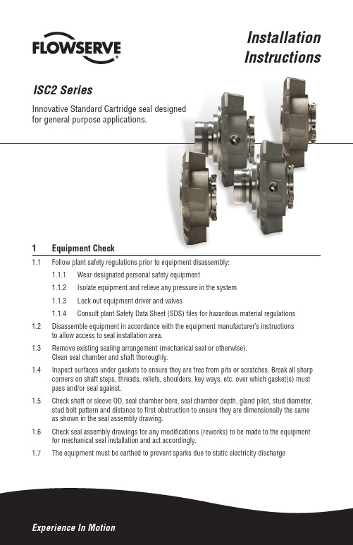
InstallationInstructions ISC2 SeriesInnovative Standard Cartridge seal designedfor general purpose applications.1 Equipment Check1.1 Follow plant safety regulations prior to equipment disassembly:1.1.1 Wear designated personal safety equipment1.1.2 Isolate equipment and relieve any pressure in the system1.1.3 Lock out equipment driver and valves1.1.4 Consult plant Safety Data Sheet (SDS) files for hazardous material regulations1.2 Disassemble equipment in accordance with the equipment manufacturer’s instructionsto allow access to seal installation area.1.3 Remove existing sealing arrangement (mechanical seal or otherwise).Clean seal chamber and shaft thoroughly.1.4 Inspect surfaces under gaskets to ensure they are free from pits or scratches. Break all sharpcorners on shaft steps, threads, reliefs, shoulders, key ways, etc. over which gasket(s) must pass and/or seal against.1.5 Check shaft or sleeve OD, seal chamber bore, seal chamber depth, gland pilot, stud diameter,stud bolt pattern and distance to first obstruction to ensure they are dimensionally the same as shown in the seal assembly drawing.1.6 Check seal assembly drawings for any modifications (reworks) to be made to the equipmentfor mechanical seal installation and act accordingly.1.7 The equipment must be earthed to prevent sparks due to static electricity discharge2Shaft runoutat any point along the shaft for ball or roller type bearings. For sleeve type bearings, refer to manufacturer instructions. If the equipment is not completely dismantled, verify runout near seal location.The above values apply to shaft speeds in the range from Flowserve representative. See Figure 1.Shaft endplayregardless of thrust bearing type. See Figure 2.Radial bearing play to verify the equipment’s suitability for the seal.Seal chamber squareness to the shaft centerline shouldbe within 0.0005 mm/mm (0.0005 inch/inch) of seal chamber bore TIR.Note: make sure that shaft endplay does not affect the reading. Verify the smoothness of the sealchamber face for a good gasket joint. See Figure 3.Concentricity of the shaft diameter (0.001 inch per 1 inch shaft diameter) to a maximum of 0.125 mm (0.005 inch) TIR. See Figure 4.+0.000 mm (+0.000 inch) API 610/682-0.025 mm (-0.001 inch) DIN/ISOSurface finish requirements32 ISC2 Seal InstallationNote: No seal setting measurements are needed to install the seal. Instructions are for end-suction back pull-out pumps. Modification of these procedures may be required for other style pumps. Consult Flowserve for installation support.DescriptionThis ISC2 seal is a versatile cartridge mounted mechanical seal, designed for ease of installation and reliable operation. No seal setting dimensions are required. Removable setting devices provide proper alignment.The ISC2 seal family consists of:ISC2-PX - Single pusher seal with stationary springs ISC2-PP - Dual pusher seal with stationary springs ISC2-BX - Single metal bellows seal with rotating bellows ISC2-BB - Dual metal bellows seal with rotating bellows ISC2-XP - Single pusher seal with a pumping device for a Plan 23 ISC2-XB - Single metal bellows seal with a pumping device for a Plan 23Figure 22.1Lubricate the shaft or pump sleeve lightly with silicone lubricant unless otherwise specified.2.2 Tighten the setting device cap screws to ensure they are tight before installation.2.3Slide the ISC2 seal cartridge onto the shaft or pump sleeve with the setting devices toward the bearing housing. See Figure 2.2.4Install the seal chamber and bolt it inplace on the bearing frame. See Figure 3.Figure 3Recommended ISC2 seal minimum set screw torque by size range: Seal mm 25 - 60 67 - 70 75 - 203 75 - 203Size (inch) (1.000 - 2.500) (2.625 - 2.750) (2.875 - 8.000) (2.875 - 8.000)Gland Size AllAllStandard Bore Enlarged Bore Torque 4.5 N-m 13.5 N-m 16.9 N-m 27.1 N-m(40 in-lbs) (120 in-lbs)(150 in-lbs)(240 in-lbs)4Figure 42.5 Position the ISC2 seal with the gland tight against the seal chamber.2.6 Orient the ISC2 seal with the ports aiming as shown on the seal assembly drawing. See Section 3 for Piping Recommendations.2.7Tighten the gland nuts evenly in a diagonal sequence. Do not over-tighten the gland nuts, as this can warp seal parts and cause leakage. Confirm adequate thread engagement before final torque setting.Recommended ISC2 seal minimum gland nut torque by size range:Seal mm 25 - 50 54 - 70 75 - 102 108 - 152 159 - 203 Size (inch) (1.000 - 2.000) (2.125 - 2.750) (2.875 - 4.000) (4.250 - 6.000) (6.250 - 8.000)Torque 20 N-m27 N-m 40 N-m47 N-m 54 N-m(15 ft-lbs) (20 ft-lbs) (30 ft-lbs) (35 ft-lbs) (40 ft-lbs)Note: Some equipment with small bore seal chambers provide limited access to the gland bolting and setting device cap screws. In some situations, the gland fasteners interfere with the setting devices and window access may require deviation from the standard fastening sequence. For example, the collar/sleeve assembly may need to be rotated slightly from its factory-set position by loosening the setting device cap screws, rotating the collar/sleeve assembly, then tightening the screws. When nonstandard processes are followed, be careful to maintain the integrity of the seal cartridge at all times.2.8Assemble the equipment per manufacturer specifications. Avoid pipe strain.Align the coupling permanufacturer specifications. 2.9With the impeller, shaft, coupling and bearings in their final operating position, tighten the drive collar set screws. See Figure 4.Note: in designs that have two smaller screws, these are quarter dog screws that hold the collar to the sleeve and should not betightened. A hex key was provided for the set screws, not for thequarter dog screws.2.10 Remove the setting devices fromscrews. See Figure 5. Save the settingdevices and fasteners for future usewhen the pump impeller is reset orwhen the seal is removed for repairs.2.11 Turn the shaft by hand to ensureunobstructed rotation.2.12 See Operational Recommendationsbefore start-up.3 Piping Recommendations3.1 Install and maintain an adequate piping plan. The ISC2 seal requires a clean, cool environmentfor maximum seal life. Typical piping plans are listed below. Contact Flowserve for additionalpiping plan information or technical support.Important: All red plastic caps/thread guards are for shipping protection only and should bereplaced with either a piping connection or a metal plug in the same metallurgy as the gland.Plan 02: d ead-ended seal chamber with no flush (single seals, always plug Flush port)Plan 03: c irculation created by the design of the seal chamber(single seals, always plug Flush port)Plan 11: default inner seal flush from pump discharge on horizontal pumps (single seals)Plan 13: d efault inner seal flush and vent from pump suction on vertical pumps (single sealsPlan 21: i nner seal flush from pump discharge through a cooler for use with hot products (single seals)Plan 23: i nner seal flush from internal pumping device through cooler(ISC2-XP and ISC2-XB designs)Plan 32: i nner seal clean external flush for use with abrasive products or products that are incompatible with the seal (single seals)Plan 52: d ual seal circulation through a low pressure reservoir (dual seals)Plan 53: d ual seal circulation through a pressurized reservoir (53A),finned tube array (53B) or piston accumulator (53C) (dual seals)Plan 62: e xternal quench on atmospheric side of seal (single seals)3.2 For dual seals, LBI (Liquid Barrier Inlet) and LBO (Liquid Barrier Outlet) are marked on thegland. ISC2 seals are unidirectional and piping the correct inlet and outlet is important toproper circulation. The liquid barrier inlet should draw from the bottom of the supportsystem while the liquid barrier outlet feeds the top of the system.53.3 For dual pressurized seal (Plan 53, double seal) operation, supply a clean, compatible barrierfluid at a pressure at least 1.7 bar (25 psi) above the seal chamber pressure. See Figure 6.The pressure of the barrier fluid must not exceed the recommended maximum pressure. Dual pressurized (Plan 53A) ISC2 with Supply Tank Figure 663.4 For dual unpressurized (Plan 52, tandem seal) operation, supply a clean, compatible bufferfluid at a pressure below the seal chamber pressure. The pressure in the seal chamber must not exceed the recommended maximum pressure.3.5 For single seal operation excluding Plan 23, ensure all ports are fitted with piping orplugs. Plans 02 and 03 must close the Flush port with a metal plug in the same metallurgy as the gland. If Plan 62 is not used, the Quench port should be plugged. The Drain port should be connected to a drain line to prevent leakage along the shaft. Note: the Quench and Drain ports are smaller than the flush port as a distinguishing feature.3.6 For single seal operation with Plan 23, FI (Flush Inlet) and FO (Flush Outlet) are markedon the gland. ISC2 seals are unidirectional and piping the correct inlet and outlet is important to proper circulation. The flush inlet should draw from the bottom of the cooler while the flushoutlet feeds the top of the cooler. Ensure piping is optimized for thermosyphon flow.4 Operational Recommendations4.1 Remove lock outs on equipment and valves.4.2 Do not start up the pump dry to check motor rotation or for any other reason. Open valves toflood pump with product fluid. Ensure that the seal flush or support system is operating. Ventair from the casing of the pump and the seal chamber before start-up.4.3 Observe the start-up. If the seal runs hot or squeals, check the seal flush system. Do not allowthe pump to run for any extended time if the seal gets hot or squeals.4.4 Do not exceed corrosion limits. The ISC2 seal is designed to resist corrosion through propermaterial selection. Do not expose the ISC2 seal materials of construction to products outside of their corrosion limits. Consult Flowserve for chemical resistance recommendations.4.5 Do not exceed pressure and speed limits established for the ISC2 seal.4.6 Do not exceed the temperature limits of the ISC2 seal based on the materials of construction.For dual seals using supply tanks with cooling coils, turn on cooling water to the supply tankbefore start-up.4.7 Do not start up or run the ISC2 seal dry. The seal chamber, pump and support systems shouldbe thoroughly vented before start-up. Buffer or barrier fluid must flood the seal cavity of dualseals at all times during operation. Process fluid must be in the seal chamber at all times during single seal operation.5 RepairsThis product is a precision sealing device. The design and dimension tolerances are critical to seal performance. Only parts supplied by Flowserve should be used to repair a seal.To order replacement parts, refer to the part code and B/M number. A spare backup seal should be stocked to reduce repair time.When seals are returned to Flowserve for repair, decontaminate the seal assembly and includean order marked "Repair or Replace." A signed certificate of decontamination must be attached.A Safety Data Sheet (SDS) must be enclosed for any product that came in contact with the seal.The seal assembly will be inspected and, if repairable, it will be rebuilt, tested, and returned.The images of parts shown in these instructions may differ visually from the actualparts due to manufacturing processes that do not affect the part function or quality.7FIS190eng REV 09/2018 Printed in USATo find your local Flowserve representativeand find out more about Flowserve Corporation,visit Flowserve Corporation has established industry leadership in the design and manufacture of its products. When properly selected, this Flowserve product is designed to perform its intended function safely during its useful life. However, the purchaser or user of Flowserve products should be aware that Flowserve products might be used in numerous applications under a wide variety of industrial service conditions. Although Flowserve can provide general guidelines, it cannot provide specific data and warnings for all possible applications. The purchaser/user must therefore assume the ultimate responsibility for the proper sizing and selection, installation, operation, and maintenance of Flowserve products. The purchaser/user should read and understand the Installation Instructions included with the product, and train its employees and contractors in the safe use of Flowserve products in connection with the specific application. While the information and specifications contained in this literature are believed to be accurate, they are supplied for informative purposes only and should not be considered certified or as a guarantee of satisfactory results by reliance thereon. Nothing contained herein is to be construed as a warranty or guarantee, express or implied, regarding any matter with respect to this product. Because Flowserve is continually improving and upgrading its product design, the specifications, dimensions and information contained herein are subject to change without notice. Should any question arise concerning these provisions, the purchaser/user should contact Flowserve Corporation at any one of its worldwide operations or offices.© 2016 Flowserve Corporation USA and Canada Kalamazoo, Michigan USA Telephone: 1 269 381 2650 Telefax: 1 269 382 8726Europe, Middle East, Africa Etten-Leur, the Netherlands Telephone: 31 765 028 200 Telefax: 31 765 028 487Asia PacificSingapore Telephone: 65 6544 6800 Telefax: 65 6214 0541Latin AmericaMexico City Telephone: 52 55 5567 7170 Telefax: 52 55 5567 4224TO REORDER REFER TO B/M #F.O.。
- 1、下载文档前请自行甄别文档内容的完整性,平台不提供额外的编辑、内容补充、找答案等附加服务。
- 2、"仅部分预览"的文档,不可在线预览部分如存在完整性等问题,可反馈申请退款(可完整预览的文档不适用该条件!)。
- 3、如文档侵犯您的权益,请联系客服反馈,我们会尽快为您处理(人工客服工作时间:9:00-18:30)。
DRI-ETG 金属缠绕垫片 Durtec®-ETG
金属齿形垫片适用于热交换器和大型容器等存在温度循环的工 况。高温耐久龙™K40-ETG齿形垫片进一步提高了垫片的承载能 力和载荷的均匀分配性能。适用的非氧化性或氧化性工况温度 可达1,000oC。
K40-ETG 金属齿形垫片
DDUURRLLOONN® ®高温耐久龙™(ETG)
HT1000-T316
无机粘合金云母板材,配0.004” 厚的316 打 孔不锈钢板夹层。
尺寸: 1,000 x 1,000 mm (39.4” x 39.4”)
DUDRULROLNO®N高® 温耐久龙™(HT1000™)
Page 5 高温耐久龙™ETG极高温垫片专为高温工况设计(包括强氧化性工况和非氧化性工况),通常为高于650oC (1,200oF), 最高可达到 1,000oC(1,800oF)的工况。在极端高温工况下,法兰联接处的扭矩保持性能是保持密 封的关键因素。高温耐久龙™ETG结合了高稳定性的抗氧化材料与柔性石墨的优异密封性能,从而能在保持 法兰联接处螺栓扭矩的同时保证良好的密封效果。 高温耐久龙™ETG设计理念为完美结合抗高温材料和经过氧化惰性处理的高等级柔性石墨。标准工业级柔性 石墨通常在450oC开始快速氧化。通过加入抗氧化惰性成分,其氧化的速度会显著地降低。 高温耐久龙™ETG的内圈和外圈是HT1000™材料。HT1000™主要成分为金云母材料和极微量的无机粘合剂。 HT1000™材料中的无机粘合成分比同属云母类矿物的蛭石(Vermiculite)产品中的无机粘合剂成分含量少 一半以上。极低的粘合成分保证了HT1000™材料具有非常低的热失重率,从而能显著提高密封材料在高温 工况中的密封性能。 高温耐久龙™ETG的性能已被广大用户公认为当今密封工业开发的有效密封极高温工况的最优技术之一。
高温耐久龙™Durtec®ETG垫片的密封贴面的抗高温性能和密封 性能都得到了极大的提升。在专利波形垫片内核的两面,密封 贴面在内圈和外圈为HT1000™材料,中间为经氧化惰性处理的 高等级柔性石墨。 专利波形内核与贴面密封材料的组合使垫片具有极好的螺栓扭 矩保持性能,防火安全性能,气密性和抗高温氧化性能 (1,000oC)。在整个垫片行业,目前没有出现综合性能完全达 到 Durtec®-ETG的产品。
Page 7
DURLON®9000(蓝色)/9000N(白色),设计针对化 工,造纸,制药,氧气及其他工业气体(可提 供氧清洗脱油脱脂垫片),食品/饮料,及其他 通用工业行业的工艺管道和设备的密封。典型 的工况需求为强腐蚀性工况,洁净工况和低温 工况等。
电介击穿, kV/mm (V/mil) ASTM D149
金属金色 金云母,含量90%以上 无机硅 -55°C (-67°F) 1,000°C (1,800°F) 1.7 (106) 18-22
39-43 55 29.6 (4,300) <4%
8 20 (508)
DURLON®高温耐久龙™ HT1000™ 主要成分为无机粘合金 云母。高温耐久龙™ 材料的主要特性是在高温工况中不 会被强氧化性介质氧化。而且本产品中的无机粘合成分 比同属云母类矿物的蛭石(Vermiculite)产品中的无机 粘合剂成分含量少一半以上。极低的粘合成分保证了本 产品具有更好的质量保持性能。在800oC (1,472oF)的高温 工况中,热失重只有不到 4% 。在 1,000oC(1,800oF)的高 温氧化性工况中也可以达到非常完好的密封效果。 本产 品成功通过了API 607 防火测试。
DURLON® 9000/9000N…………...…..……………7 DURLON® 9200……………………..………………….8 DURLON® 9400………………………..……………….9 DURLON® 9600…………………………..…………….10 Virgin PTFE…………………………………..…………….11 DURLON® RCA低应力垫片………………….……..…….......12 DURLON® 膨体聚四氟乙烯带………………………………..13 非石棉压缩纤维板材垫片 DURLON® 5000.………………………………………...14 DURLON® 5300………………………………………….15 DURLON® 7900/7925/7950………………….……16 DURLON® 7910.…………………………………………17 DURLON® 8300………………………………………….18 DURLON® 8400……………...…………...……….…....19 DURLON® 8500………………………………………….20 DURLON® 8600………………………………………….21 DURLON® 8700……………………….…………………22 DURLON® 法兰绝缘垫片………………………..………………7,19,35 DURLON® 柔性石墨板材垫片……………..……….…...……23 金属缠绕垫片………………………………………………………….24 型式…….………………………………………………………25 色标….…………………………………………………………26 标记……………………………………………………….……27 改良型云母-石墨技术….……………………………...28 金属环垫(RTJ) ……………………………………………………….29 型式………………………………………………………..…..30 柔性石墨波纹垫片(CFG)…………………………………………31 专利防火Durtec®波形垫片……………………………………32 防火性,尺寸,型式及材料 ……………………….33 通用热交换器垫片……………………………………...34 金属齿形垫片………………………………………………………....35 型式…………………………….…………………….………..36 Identa-Seal® Viton氟橡胶垫片及O型环…………….. 76 附录(英文版) 防止密封失效方法…………………………….……………….......37 垫片温度压力关系………………………………………….……...38 紧固螺栓工作表……………………………………………………..39 垫片工况数据表………………………………………….………….40 螺栓紧固扭矩值………………………………………………….....41-42 化学兼容性表…………………..…………………………………….43-50 金属垫片尺寸表 (inches)……………...………………………..51,53-59, 67 金属垫片尺寸表 (mm)……………….…………..……………....52, 60-66, 68 Durtec® 垫片尺寸(inches & mm)…...…..…..…..…..……69-71 非金属切割垫片尺寸表…………………………………………. 72 公制英制单位转换表…………………………………………….. 73 法兰密封面精度要求…………………………………………….. 74 金属环垫材料硬度值…………………………………………….. 75
在中国的化工行业,DURLON®是中国化工行业标准HG/T20592-20635-2009中推荐的密封材料品 牌,其产品技术参数是整个化工行业进行设计和密封材料选型的重要依据之一。
当今世界各国正在制定和实施严格的洁净空气法案。所以,耐久龙TM的主要设计目标之一是最大 程度地提高材料的密封性能及可靠性,以满足控制逃逸性排放(fugitive emission)的要求。
耐久龙TM
DURLON ®
杜拉巴尔密封技术手册
质量 | 性能 | 服务
DURLON® 耐久龙TMDURLON®耐久龙TM密封科技
加拿大杜拉巴尔创立于1911年,具有超过百年的密封专业技术经验。DURLON®全系列密封材料
科技及完善的密封技术服务一直处于世界领先地位。
耐久龙TM系列密封产品经过多年不断地研发和改良,适用于极其广泛的应用工况。耐久龙TM被广 泛应用于炼油,石油化学,化工,电力(火电及核电),造纸,食品,药品等终端用户及其相应 的设备制造,工程设计及施工等领域。耐久龙TM 适用工况的温度范围从低温零下268摄氏度到高 温1000摄氏度,压力从真空工况到美标2500磅级。耐久龙TM可以安全可靠地密封各种高危介质 如:液态氧气,光气,氢氟酸等等。在空分行业,耐久龙TM具有经广大行业用户应用验证的垫片 氧清洗脱油脱脂技术。对于大尺寸的PTFE垫片(直径大于1.5米以上),耐久龙TM具有先进成熟 的垫片焊接技术。耐久龙TM非金属板材垫片具有齐全的尺寸规格,厚度范围从0.4毫米到8.0毫 米,板幅最大可达3米X3米。因此,耐久龙TM的用户再也不需要选择和库存很多种类的密封材 料。这将在很大程度上改善用户生产过程的安全性。减少使用密封材料的种类意味着降低了在多 种工况下不当选用密封材料的潜在安全风险。
Page 4
颜色 结构系统 粘合 温度
Min Max
密度 g/cc (lbs/ft3)
压缩率, % ASTM F36J
回弹率, % ASTM F36J
蠕变松弛, % ASTM F38
拉伸强度 ASTM F152, MPa (psi)
热失重 @ 800oC DIN 52911
氮气气密性 cc/min ASTM F2378
基于以上原因,世界各地的广大终端用户及相应的设备制造,工程设计及施工领域正在将耐久龙 TM作为安全密封材料的首选。
DURLON®
内容目录
DURLON® 高温耐久龙TM(HT1000TM)板材垫片 ..4 DURLON® 高温耐久龙TM ETGTM金属垫片………...……5
型式…………………..………………………………….…...6 聚四氟乙烯板材的含水硅酸钾盐/硅 酸镁盐。层状纤维结构使其具有优异的气密性和可压缩 性。它的物理特性是柔韧,有弹性,具有很高的拉伸强 度,在层状结构的垂直方向可以抵抗巨大的机械压力, 它具有很强的抗化学性,防火性,不熔性,阻燃性和拒 燃性,是在各种高温氧化性严苛工况中替代石棉和石墨 的极佳密封材料。高温耐久龙™ 能确保在各种极端高温 工况中保持优良的密封性能。