WT_SOM9854_S1核心板说明书(1)
海克智动 智能主控板说明书
海克智动智能主控板说明书
1、简介
智能主控板是新风机中控制风机、风阀等主控电路板,我们目前有两种主控板,即220VAC电容调速三档、220VAC强控三档。
新风机就是客户自己的新风主机,我们帮助客户设计新风主机的主控电路板,主控板控制风机、新风阀、电击离子、通信接口(RS-485)等。
新风机可以通过B3工业空气质量监测仪的空气质量数据自动运行,也可以通过液晶触控屏手动控制新风机运行状态。
具体运行状态可根据客户实际要求设计。
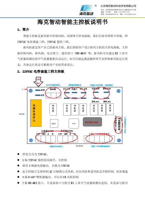
2、220VAC电容调速三档主控板
●供电方式为220VAC。
●1路220VAC强控的风阀开、关控制
●留有3路继电器输出,负载为220VAC
●此主控板只支持控制AC后倾离心式风机,对出风机和进风机是并联控制,电容调速●3路0-10V模拟量输出,可以对CE风机控制
●2路RS-485接口,主设备接口与我司B3工业空气质量检测仪连接,从设备与我司
X3液晶触控屏连接
●1路PM2.5传感器接口,可以与我司PM2.5传感器连接
3、220VAC强控三档主控板
●供电方式,交流220V
●风机控制是220VAC强控三档调速
●3路继电器输出,负载为220VACV
●2组风阀220VAC强控开、闭
●2路模拟量输入,0-10V的AD转换
●4路数字量输入,高达10V的数字量
●2路0-10V模拟量输出,可以对CE风机控制
●2路RS485接口,主设备接口与我司B3工业空气质量监测仪连接,从设备与我司X3
液晶触控屏连接。
AD9850_1模块使说明书

串并模式转 换插针 数据接口
正弦波输出 RF-OUT
矩形波输出
正弦波幅度 调节 200mV-2V 电源接反保 护 AD9850 125M AD9851 30M 70M 滤波器
矩形波输出
插入跳线帽短路为串行 模式,断开为并行模式。
模块测试============================================================
1:朋友拿到模块后,先不急着调电位器,电位器出厂已调到幅度调到 2V VPP。朋友调试 出信号后,如果有需要再调节电位器,调幅度。 2:问我按照你的方法接怎么不出信号。 答:给大家的模块和程序都是已经调试成功程序是标准 51 C 程序。如果是别的类型单片机 如 STM32,AVR,MSP430 请朋友自行移值。朋友要注意一些比如自已的单片机 IO 口是不 是连其它器件,比如 DS18B20 DS1302 数码管等一些器件。这些器件会影响时序,导致出 不来信号。 3:为什么程序给了 1K 的信号,但出来频率相差很多。 答:这里由于 D0-D7 数据口跟单片机数据口没有连好导致。请朋友仔细检查核对后,肯定 OK! 4:你的模块可以用 3.3V 供电吗? 答:模块设计在 5V 供电,在 3.3V 勉强能用,但不建议! 5:我用示波器量,出来的波形幅度怎么用 20 多 V? 答:模块采用 5V 供电,不可能出 20 多 V,唯一可能就是示波器表笔打到*1 档,再把示波 器打到*10 就恢复了。 6:为什么我的正弦波出来了,但方波出不来 答:可能是调节占空比电位器调的太多了,重新调试即可解决
J2)
RF_OUT 端能测试到对应输出 1KHz 正弦波信号幅度 2V VPP。如需测试方波,调节可 变电位器,在 VOUTP 和 VOUTN 端测试到方波。电位器调节占空比
集特核心板GCE-2001-01说明书

说明除列明随产品配置的配件外,本手册包含的内容并不代表本公司的承诺,本公司保留对此手册更改的权利,且不另行通知。
对于任何因安装、使用不当而导致的直接、间接、有意或无意的损坏及隐患概不负责。
订购产品前,请向经销商详细了解产品性能是否符合您的需求。
本手册所涉及到的其他商标,其所有权为相应的产品厂家所拥有。
本手册内容受版权保护,版权所有。
未经许可,不得以机械的、电子的或其它任何方式进行复制。
温馨提示1、产品使用前,务必请仔细阅读产品说明书。
2、对未准备安装的主板,应将其保存在防静电保护袋中。
3、在从包装袋中拿主板前,应将手先置于接地金属物体上一会儿,以释放身体及手中的静电4、在使用前,宜将主板置于稳固的平面上。
5、请保持主板的干燥,散热片的开口缝槽是用于通风,避免机箱内的部件过热。
请勿将此类开口掩盖或堵塞。
6、在将主板与电源连接前,请确认电源电压值。
7、请将电源线置于不会被践踏的地方,且不要在电源线上堆置任何物件。
8、当您需连接或拔除任何设备前,须确定所有的电源线事先已被拔掉。
9、为避免人体被电击或产品被损坏,在每次对整机、板卡进行拔插或重新配置时,须先关闭交流电源或将交流电源线从电源插座中拔掉。
10、请留意手册上提到的所有注意和警告事项。
11、为避免频繁开关机对产品造成不必要的损伤,关机后,应至少等待30秒后再开机。
12、设备在使用过程中出现异常情况,请找专业人员处理。
13、请不要将本设备置于或保存在环境温度高于70℃上,否则会对设备造成伤害。
目录目录 (1)1.产品简介 (1)1.1概述11.2产品特点 (2)1.3产品指标 (2)2.细参数说明 (4)2.1COMe外形尺寸 (4)2.2COMe连接器接口定义 (5)1.产品简介1.1概述GCE-2001-01基于飞腾D2000-8处理器的COMe模块,模块按照PICMG COMExpress 规范设计,符合COMExpress Type6Rev2.0接口类型定义,尺寸规格为Basic规格。
Omega CSC32K Benchtop Controller产品说明书

P
CSC32K Benchtop Controller shown with LHM Series Heating Mantle, $139, (Flask not included), and KMTXL-125G-12 Thermocouple Probe, $27.95. See page A-45.
0.5 (0.9) 0.25 (4.5)
0 to 50 mV (1 Ω shunt resistor
Copper-Constantan
-200 to -250°C/-273 to 482°F
0.25 (4.5)
supplied for mA inputs) Calibration Accuracy: ±0.25% of Full Scale ±1.5°C (±2.7°F)
• In addition, up to 12 controllers can be displayed on a single chart, or individual charts can be set up for each instrument.
• A virtual full color chart recorder can log process variables such as: °C, °F, Bar, PSI, pH, rH, or user defined engineering units
RTD, Process Voltage or Current Input
ߜ Two 5 Amp 120 Vac SSR Outputs Standard
ߜ Second Output May be Used for Control or One of Five Types of Alarms
智能TFT-LCD模块STWI104WT-01设备说明书

Intelligent TFT-LCD ModuleModelSTWI104WT-01Equipment ManualContentsPreface (3)1 Introduction (5)2 Technical Parameters (10)3 Interface Description (15)4 Accessories (16)5 Physical Dimensions (18)6 Electrical Components (19)7 Naming Rule (20)8 International Certification (21)APPENDIX (22)Glossary (24)PrefaceThis equipment manual is part of our Intelligent TFT-LCD Module documentation. It provides the information in regards of operation, installation, configuration, function, system as well as its technical design and working principle.Organization of the manualThe STWI104WT-01 equipment manual is organized into the following chapters:Products through its Online services as follows:- Official website: https:///https://- Official forum: https:///- Telephone: 0086-10-84351669Other supportIn need of technical queries, please contact STONE representatives in the subsidiaries and branches responsible for your area.PrefaceTrademarksSTONE registered trademarks are as below:- STONE- STONE TECH- Intelligent HMI- Intelligent TFT-LCD Module- Smart TFT-LCD ModuleAbbreviationsThe abbreviation table in this equipment manual is as below:LED Light Emitting DiodeCPU Central Processing UnitESD Electrostatic Sensitive DeviceHMI Human Machine InterfaceIF InterfaceLCD Liquid Crystal DisplayUART Universal Asynchronous Receiver/TransmitterCOM CommercialDIN Data InputDOUT Data OutputVIN Voltage InputGND GroundTP Touch PanelA list of all the technical terms together with their explanations is provided in the glossary at the end of this manual.1IntroductionThis chapter contains general information of:- Brief Introduction- Warranty- Product Characteristics- Application Area- Working principle- Operation Processing- Software OperationIntroduction1.1 Brief IntroductionThe STWI104WT-01 has been used as Equipment TFT dispaly & Touch controller. It includes processor, control program, TFT driver, flash memory, UART port, touch screen, power supply etc., and the important is it can supply the Json Code & Hex Code instruction sets, so that it can be controlled by Any MCU.The STWI104WT-01 can perform all basic functions, such as Vector font display, image display, curve display as well as touch function, Video & Audio function etc. The User Interface can be more abundant and various. And the flash memory can store your data, configuration files, image file, font file, video file and audio file etc.1.2 WarrantyAll products purchased from our company are guaranteed to keep in good repair for3 years. If quality problems (except human error) happen in guarantee period, our company will maintain for free to replace the broken one unconditionally.1.3 Product Characteristics- With Cortex A8 CPU / 256MB Flash / TFT Driving device- Controlled by any MCU via Json & Hex Code Instruction- Display Image / Text / Curve / Video- 262K (18bit) colour TFT display- With / without Touch Screen- RS232 / RS422 / RS485 / TTL UART Interface & USB port Downloading- Ethernet port / WIFI Remote Control- Wide voltage range / Strong Working Temperature- Easy to use! Powerful function! Saving Much Development cost and time!1.4 Application AreaWidely used in various industrial field- Medical & Beauty Equipment- Engineering Machinery and Vehicle Equipment- Electronic Instrument- Industrial Control System- Electric Power Industry- Civil Electronic Equipment- Automation Equipment- Traffic Field- New energy project- IOT applicationsEtc.Introduction1.5 Working PrincipleThe Intelligent TFT-LCD Module communicates with the Customer’sMCU / CPU / FPGA / PLC via JSON Code and HEX Code Instructions, then the MCU can control its connected equipment to work according to the received instructions.Figure 1.3-1 Configuration and process control phaseIntroduction1.6 Operation ProcessingOnly 3 steps to operate our TFT-LCD Module:⚫Build a new project by STONE GUI Design Software.⚫Connect with customer’s MCU through RS232,RS422,RS485,TTL directly, Plug & Play. ⚫Write a simple program for MCU to control the TFT-LCD Module via Instruction Sets.The communication protocol is built with 2 parts:1)Initiative Instruction - JSON Code (MCU→TFT-LCD Module)Frame header instruction code widget type widget name data Frame tail ST< {"cmd_code":"set_value","type":"label","widget":"label2","value":5} >ET 2)Passive Instruction - HEX Code (TFT-LCD Module→MCU)Frame header CMD LEN DATA Frame tail CRC16 53 54 3C 10 62 00 096C 61 62 65 6C 3F A1 47 AE3E 45 54 6C 8B More information, please refer to the document of Instruction Sets.Introduction.7 Software OperationWe will offer a simple & powerful "Stone GUI design Software" to help you to design the new project for Intelligent TFT-LCD Module basic on Windows system or MacOS system.2Technical ParametersThis chapter contains technical data on:- Physical Parameters:Physical ParametersDisplay- Hardware Parameters:ProcessorMemoryInterfacePower Supply- Storage & TestElectrical CharacteristicsAmbient ConditionsNoise ImmunityRadio Interference- Support DeviceSupport DeviceTechnical ParametersTechnical ParametersTechnical ParametersTechnical Parameters3Interface DescriptionThis chapter contains the description of the interfaces:- VVC- NC- DOUT- DIN- GNDCommunication Interface DefinitionI: Input O: Output P: Power: 1. Adopting the 8 Pin 2mm spacing socket. Model Code: A2008WR-S-8P2. Direction of the signal was defined with TFT-LCD Module;“I” refers to the signal from the user’s MCU transmitted to the TFT-LCD Module.3. Pins with the same definition are connected together in the module inside.4. RS232, RS422, RS485, TTL port can be default which need to point out in the order.: The selection of Baud rate for the serial interfaceBaud rate120024004800)Serial Port Defind:4AccessoriesThis chapter contains the accessories:- Double 8-pin Connect Cable- 8-pin Socket- Type A USB Cable- Converter: USB ⇌ RS232 / RS422 / RS485 / TTL - IP65 Plastic Box (optional)- Metal Bezel (optional)This chapter contains the information of Physical Dimensions.Figure 5-1 STWI104WT-01 dimensionThis chapter contains the brands of the components:- TFT Panel- Touch Screen- CPU- LCD Controller- Flash memory- Connecter- Capacitance- IC7Naming RuleThis chapter contains the naming rule: As sample STWI070WT-01E8International CertificationThis chapter contains the certification we passed:- CE Certificate- ROHS Certificate- FCC Certificate- ISO9001:2008 Quality SystemCE Certificate FCC CertificateRoHS Certificate ISO9001:2008APPENDIXAPPENDIXESD GuidelinesWhat does ESD mean?Virtually all present-day modules incorporate highly integrated MOS devices or components. For technological reasons, these electronic components are very sensitive to overvoltages and consequently therefore to electrostatic discharge:These devices are referred to in German as Elektrostatisch GefährdetenBauelemente/ Baugruppen: ºEGBºThe more frequent international name is:ºESDº (E lectrostatic Sensitive Device)The following symbol on plates on cabinets, mounting racks or packages draws attention to the use of electrostatic sensitive devices and thus to the contact sensitivity of the assemblies concerned:ESDs may be destroyed by voltages and energies well below the perception threshold of persons. Voltages of this kind occur as soon as a device or an assembly is touched by a person who is not electrostatically discharged . Devices exposed to such overvoltages cannot immediately be detected as defective in the majority of cases since faulty behavior may occur only after a long period of operation.Precautions against electrostatic dischargeMost plastics are capable of carrying high charges and it is therefore imperative that they be kept away from sensitive components.When handling electrostatic sensitive devices, make sure that persons, workplaces andpackages are properly grounded.APPENDIX Handling ESD assembliesA general rule is that assemblies should be touched only when this cannot be avoided owing to the work that has to performed on them. Under no circumstances should you handle printed-circuit boards by touching device pins or circuitry.You should touch devices only if● you are grounded by permanently wearing an ESD wrist strap or●you are wearing ESD shoes or ESD shoe-grounding protection straps in conjunctionwith an ESD floor.Before you touch an electronic assembly, your body must be discharged. The simplest way of doing this is to touch a conductive, grounded object immediately beforehand ± for example, bare metal parts of a cabinet, water pipe etc.Assemblies should not be brought into contact with charge-susceptible and highly insulating materials such as plastic films, insulating table tops and items of clothing etc. containing synthetic fibers.Assemblies should be deposited only on conductive surfaces (tables with an ESD coating, conductive ESD cellular material, ESD bags, ESD shipping containers).Do not place assemblies near visual display units, monitors or television sets (minimum distance to screen > 10 cm).Measuring and modifying ESD assembliesPerform measurements on ESD assemblies only when● the measuring instrument is grounded ± for example, by means of a protective conductor± or● the measuring head has been briefly discharged before measurements are made with a potential-free measuring instrument ± for example, by touching a bare metal control cabinet.When soldering, use only grounded soldering irons.Shipping ESD assembliesAlways store and ship assemblies and devices in conductive packing ± for example, metallized plastic boxes and tin cans.If packing is not conductive, assemblies must be conductively wrapped before they are packed. You can use, for example, conductive foam rubber, ESD bags, domestic aluminum foil or paper (never use plastic bags or foils).With assemblies containing fitted batteries, make sure that the conductive packing does not come into contact with or short-circuit battery connectors. If necessary, cover the connectors beforehand with insulating tape or insulating material.GlossaryBaud rateRate of speed at which data is downloaded. Baud rate is specified in Bit/s.BootA loading process which downloads the operating system in the working memory of the operating unit.Command SetHex Code, the MCU can control the TFT Module via the command set.Configuration fileIt can be created by the softwares.DownloadDownload the image, configuration files and data through mini USB port or USB port.Download modeThrough mini USB port or USB port.GlossaryFlash memoryProgrammable memory which can be electrically deleted and written to again segment-by-segment.Half Brightness LifeThe period of time after which the brightness tube only achieves 50% of the original value.Input fieldEnables the user to enter values which are subsequently sent to the MCU.MCUMicro Control Unit, it is widely used in the industrial control.Normal operationOperating unit operating mode in which messages are displayed and screens can be operated.GlossaryOutput fieldDisplays current values from the MCU on the operating unit.Process screenThe display of process values and process progress on the operating unit in the form of screens, which may contain graphics, texts and values.RS485Standard interface for serial data transfer at a very high transmission rate.ScreenA screen displays all the logically related process data on the operating unit, wherebythe individual values can be modified.Touch panelThis is an operating unit without a keyboard. The touch panel (abbreviated to TP) is operated via the contact-sensitive screen elements.。
高科特实际产品说明书
4
Specifications are subject to change without notice (21.06.2021)
Solid State Relays Accessories, Screw Kits Types SRWKIT…
Ordering Key
Screw Kit Screw size Screw length
0.5 Nm -20° to + 70°C [-4 to +158°F] -40° to + 100°C [-40° to +212°F] DIN EN 50022, 50035
DIN Adaptor for 1-phase SSRs
DIN rail adaptor module for mounting the 1-phase SSR series RA, RD, RM, RS and RAM directly on DIN rail.
Type
UL style 2547 UL style 2464 UL style 2464 UL style 2464 UL style 2464 UL style 2464
Cable size
0.14mm2 0.14mm2 0.14mm2 0.25mm2 0.14mm2 0.14mm2
Termination
- Width x Height x Thickness = 35 x 43 x 0.25 mm
- Packing qty. 50 pcs.
RZHT
- Graphite thermal pad for RZ3 series with adhesive on one side
- Width x Height x Thickness = 70 x 77 x 0.25 mm
华克仕 K-FT2K-Core 核心板说明书
使用产品之前请仔细阅读产品说明书K-FT2K-Core核心板说明书版本:v1.1版本更新表目录1注意事项 (1)2产品概述 (2)3产品规格 (3)4实物接口介绍 (4)4.1主板正反面图 (4)4.2主板加散热器图 (5)4.3主板尺寸图 (6)5接口功能定义 (7)5.1功能分布图 (7)5.2丝印描述 (8)5.3接口定义 (9)1注意事项商标本手册所提及的商标与名称都归其所属公司所有。
注意1. 使用前,请先详细阅读说明书,避免误操作导致产品损坏;2. 请将此产品放置在-20℃<=工作环境<=+60℃、90%RH的环境下,以免因过冷、热或受潮导致产品损坏;3 请勿将此产品做强烈的机械运动,以及在没有作好静电防护之前对此产品操作;4. 在安装任何外接卡或模组之前,請先关闭电源;5. 禁止对主板产品进行私自更改、拆焊,对此所导致的任何后果我司不承担任何责任;K-FT2K-Core是一款基于飞腾FT-2000/4处理器,采用采用COM Express Basic板型的核心板,尺寸为125*95mm。
K-FT2K-Core采用飞腾FT-2000/4四核芯处理器。
板载2条DDR4 SO-DIMM内存插槽。
K-FT2k-Core的COMe插槽,集成2路MAC,可外加PHY芯片扩展出2路千兆网口;集成1*PCIe-X16、2*PCIe-X8、2*PCIe-X1扩展资源,集成4*UART接口,可扩展RS232串口;集成I2C、LPC、HDA等总线资源。
主板特点:★飞腾FT-2000/4四核芯处理器;★COM Express Basic核心板小尺寸;★板载DDR4笔记本内存插槽;★丰富的PCIe扩展资源;4实物接口介绍4.1主板正反面图4.2主板加散热器图4.3主板尺寸图注意:上图单位统为毫米(mm)5接口功能定义5.1功能分布图5.2丝印描述5.3接口定义主板插针、跳线定义续1。
核星说明书
这会引起变频器内部半导体元件的损坏
-3-
1、验收
当心
l 不要安装或运行任何已经损坏或带有故障零件的变频器。 否则会导致人身伤害或设备损坏。
本章叙述变频器交付用户后的检验方法。
1-1、检验
1-1-1、验收检查 下表为检查项目: 检查项目
变频器型号是否和订单上一致? 有无部件损坏?
3、接线………………………………………………………………………………7
3-1、外围设备和任选件的接线…………………………………………………9 3-2、连接图………………………………………………………………………10 3-3、主回路的接线………………………………………………………………11 3-4、接地…………………………………………………………………………14 3-5、控制电路的接线……………………………………………………………15 3-6、接线检查……………………………………………………………………17
★ 放射性材料会影响本设备的使用。
★ 易燃物品、稀释剂、溶剂应远离本设备。
2-4、安装间隙
HX0886 系 列 变 频 器 垂 直 安 装 时 , 要 留 有 足 够 的 散 热 空 间 , 以 保 证 有 效 地 冷
却
.
-6-
出风口
出风口
大于 mm
FWD REV JOG LCL RUN FLT
MO N NEG Hz S % A
-2-
安全运行的注意事项
HX0886 系列变频器 安装、运行、维护或检查之前要认真阅读本说明书。
说明书中有关安全运行的注意事项分类成“警告”或“当心”。
警告 指出潜在的危险情况,如果不避免,可能会导致人身伤亡。
Eaton 198942 商品说明书
Eaton 198942Eaton Moeller® series Rapid Link - Speed controllers, 2.4 A, 0.75 kW, Sensor input 4, Actuator output 2, 230/277 V AC, PROFINET, HAN Q4/2, STO (Safe Torque Off)Allgemeine spezifikationEaton Moeller® series Rapid Link Speed controller198942157 mm270 mm 220 mm 3.45 kgRoHS UL approval IEC/EN 61800-5-1 CE UL 61800-5-14015081970001RASP5-2422PNT-4120010S1Product NameCatalog NumberProduct Length/Depth Product Height Product Width Product Weight Certifications Catalog Notes EANModel Code3 fixed speeds and 1 potentiometer speedcan be switched over from U/f to (vector) speed control Connection of supply voltage via adapter cable on round or flexible busbar junctionParameterization: drivesConnectParameterization: FieldbusParameterization: drivesConnect mobile (App) Parameterization: KeypadInternal DC linkKey switch position AUTOKey switch position OFF/RESETSelector switch (Positions: REV - OFF - FWD)IGBT inverterPC connectionTwo sensor inputs through M12 sockets (max. 150 mA) for quick stop and interlocked manual operationPTC thermistor monitoringThermo-click with safe isolation2 Actuator outputsControl unitKey switch position HAND3 fixed speedsSTO (Safe Torque Off)1 potentiometer speedFor actuation of motors with mechanical brake NEMA 12IP651st and 2nd environments (according to EN 61800-3)IIISpeed controllerPROFINET IOC1: for conducted emissions onlyC2, C3: depending on the motor cable length, the connected load, and ambient conditions. External radio interference suppression filters (optional) may be necessary.2000 VPhase-earthed AC supply systems are not permitted.AC voltageCenter-point earthed star network (TN-S network)Vertical15 g, Mechanical, According to IEC/EN 60068-2-27, 11 ms, Half-sinusoidal shock 11 ms, 1000 shocks per shaftResistance: 10 - 150 Hz, Oscillation frequencyResistance: 6 Hz, Amplitude 0.15 mmResistance: According to IEC/EN 60068-2-6Resistance: 57 Hz, Amplitude transition frequency on acceleration Above 1000 m with 1 % performance reduction per 100 m Max. 2000 m-10 °C40 °C-40 °C70 °CFeatures Fitted with:Functions Degree of protectionElectromagnetic compatibility Overvoltage categoryProduct categoryProtocolRadio interference classRated impulse withstand voltage (Uimp) System configuration typeMounting position Shock resistance Vibration AltitudeAmbient operating temperature - min Ambient operating temperature - max Ambient storage temperature - min Ambient storage temperature - max Climatic proofing< 95 %, no condensationIn accordance with IEC/EN 50178Current limitationAdjustable, motor, main circuit0.2 - 2.4 A, motor, main circuitDelay time< 10 ms, On-delay< 10 ms, Off-delayEfficiency97 % (η)Input current ILN at 150% overload2.5 ALeakage current at ground IPE - max3.5 mAMains current distortion120 %Mains switch-on frequencyMaximum of one time every 60 secondsMains voltage - min380 VMains voltage - max480 VMains voltage tolerance380 - 480 V (-10 %/+10 %, at 50/60 Hz)Operating modeBLDC motorsSensorless vector control (SLV)Synchronous reluctance motorsU/f controlPM and LSPM motorsOutput frequency - min0 HzOutput frequency - max500 HzOverload currentAt 40 °CFor 60 s every 600 sOverload current IL at 150% overload3.6 A45 Hz66 Hz0.75 kW400 V AC, 3-phase480 V AC, 3-phase0.1 Hz (Frequency resolution, setpoint value)200 %, IH, max. starting current (High Overload), For 2 seconds every 20 seconds, Power section50/60 Hz8 kHz, 4 - 32 kHz adjustable, fPWM, Power section, Main circuitPhase-earthed AC supply systems are not permitted.AC voltageCenter-point earthed star network (TN-S network)1 HP≤ 0.6 A (max. 6 A for 120 ms), Actuator for external motor brake≤ 30 % (I/Ie)Adjustable to 100 % (I/Ie), DC - Main circuit230/277 V AC -15 % / +10 %, Actuator for external motor brake10 kAType 1 coordination via the power bus' feeder unit, Main circuit24 V DC (-15 %/+20 %, external via AS-Interface® plug)230/277 V AC (external brake 50/60 Hz)PROFINET, optionalPlug type: HAN Q4/2Max. total power consumption from AS-Interface® power supply unit (30 V): 250 mANumber of slave addresses: 31 (AS-Interface®) Specification: S-7.4 (AS-Interface®)C2 ≤ 5 m, maximum motor cable length C1 ≤ 1 m, maximum motor cable length C3 ≤ 25 m, maximum motor cable lengthMeets the product standard's requirements.Rated frequency - minRated frequency - maxRated operational power at 380/400 V, 50 Hz, 3-phase Rated operational voltageResolutionStarting current - maxSupply frequencySwitching frequencySystem configuration type Assigned motor power at 460/480 V, 60 Hz, 3-phase Braking currentBraking torqueBraking voltageRated conditional short-circuit current (Iq)Short-circuit protection (external output circuits) Rated control voltage (Uc)Communication interfaceConnectionInterfacesCable length10.2.2 Corrosion resistanceMeets the product standard's requirements.Meets the product standard's requirements.Meets the product standard's requirements.Meets the product standard's requirements.Does not apply, since the entire switchgear needs to be evaluated.Does not apply, since the entire switchgear needs to be evaluated.Meets the product standard's requirements.Does not apply, since the entire switchgear needs to be evaluated.Meets the product standard's requirements.Does not apply, since the entire switchgear needs to be evaluated.Does not apply, since the entire switchgear needs to be evaluated.Is the panel builder's responsibility.Is the panel builder's responsibility.Is the panel builder's responsibility.Is the panel builder's responsibility.Is the panel builder's responsibility.Generation change from RA-SP to RASP 4.0 Elektromagnetische Verträglichkeit (EMV)Generation change RAMO4 to RAMO5Generation change from RA-MO to RAMO 4.0 Generationswechsel RASP4 zu RASP5Configuration to Rockwell PLC for Rapid LinkConfiguration to Rockwell PLC Rapid Link 5 Generationenwechsel RA-SP zu RASP5Generationentausch RAMO4 zu RAMO5Generation Change RA-SP to RASP5Firmware Update RASP 4.0Generationentausch RA-SP zu RASP4.0Generation Change RASP4 to RASP5Generationentausch RA-MO zu RAMO4.0Anschluss von Frequenzumrichtern an GeneratornetzeMN040003_DEMN034004_DERapid Link 5 - brochureDA-SW-drivesConnectDA-SW-drivesConnect - InstallationshilfeDA-SW-USB Driver DX-COM-STICK3-KITDA-SW-USB Driver PC Cable DX-CBL-PC-1M5DA-SW-Driver DX-CBL-PC-3M0DA-SW-drivesConnect - installation helpMaterial handling applications - airports, warehouses and intra-logistics ETN.RASP5-2422PNT-4120010S1.edzIL034093ZUDE | Rapid Link 5Sortimentskatalog Antriebstechnik-DE10.2.3.1 Verification of thermal stability of enclosures10.2.3.2 Verification of resistance of insulating materials to normal heat10.2.3.3 Resist. of insul. mat. to abnormal heat/fire by internal elect. effects10.2.4 Resistance to ultra-violet (UV) radiation10.2.5 Lifting10.2.6 Mechanical impact10.2.7 Inscriptions10.3 Degree of protection of assemblies10.4 Clearances and creepage distances10.5 Protection against electric shock10.6 Incorporation of switching devices and components10.7 Internal electrical circuits and connections10.8 Connections for external conductors10.9.2 Power-frequency electric strength10.9.3 Impulse withstand voltage10.9.4 Testing of enclosures made of insulating material Anmerkungen zur AnwendungBenutzerhandbücherBroschüreneCAD model Installationsanleitung InstallationsvideosKatalogeEaton Konzern plc Eaton-Haus30 Pembroke-Straße Dublin 4, Irland © 2023 Eaton. Alle Rechte vorbehalten. Eaton ist eine eingetrageneMarke.Alle anderen Warenzeichen sindEigentum ihrer jeweiligenBesitzer./socialmediaThe panel builder is responsible for the temperature rise calculation. Eaton will provide heat dissipation data for the devices.Is the panel builder's responsibility. The specifications for the switchgear must be observed.Is the panel builder's responsibility. The specifications for the switchgear must be observed.The device meets the requirements, provided the information in the instruction leaflet (IL) is observed.ramo5_v39.dwgrasp5_v39.stpeaton-bus-adapter-rapidlink-speed-controller-dimensions-003.eps eaton-bus-adapter-rapidlink-speed-controller-dimensions-002.eps eaton-bus-adapter-rapidlink-speed-controller-dimensions.eps eaton-bus-adapter-rapidlink-speed-controller-dimensions-004.eps10.10 Temperature rise10.11 Short-circuit rating10.12 Electromagnetic compatibility 10.13 Mechanical function mCAD model Zeichnungen。
瑞丰WI-E-045 A1 产品说明书.pdf_1718725410.5614424
applications which has special requirement in quality and reliability. 如产品需要用在有特殊质量要求及可靠性要求的地方,请提前咨询瑞丰的销售人员以取得相关信息。
4. Without Refond permission, customer shouldn’t disassemble and analyze the LEDs. If the customer find invalid product, please notice Refond in written form.在取得瑞丰的同意前,客户不应该对产品进行拆解分析,如发现失效产品,请直接书面通知瑞丰。
Features 特征Extremely wide viewing angle.发光角度大Suitable for all SMT assembly and solder process.适用于所有的SMT 组装和焊接工艺 Moisture sensitivity level: Level 3.防潮等级 Level 3Package:4000pcs/reel.包装每卷4000pcsRoHS compliant. 满足RoHS 要求Description 描述The White LED which was fabricated by using a blue chip and the phosphor 该产品为白光LED ,是由蓝光芯片激发荧光粉而形成Applications 应用Optical indicator.光学指示Switch and Symbol,Display.开关和标识、显示器等General use.其他应用Package Dimension 外观尺寸NOTES:1.All dimensions units are millimeters. (所有尺寸标注单位为毫米)2.All dimensions tolerances are ±0.2mm unless otherwise noted. (除特别标注外,所有尺寸公差为±0.2毫米)Electrical / Optical Characteristics at Ts=25°C 电性与光学特性-- -- 450Note:备注Vr=5V For test conditions. Vr=5v为测试分选条件。
- 1、下载文档前请自行甄别文档内容的完整性,平台不提供额外的编辑、内容补充、找答案等附加服务。
- 2、"仅部分预览"的文档,不可在线预览部分如存在完整性等问题,可反馈申请退款(可完整预览的文档不适用该条件!)。
- 3、如文档侵犯您的权益,请联系客服反馈,我们会尽快为您处理(人工客服工作时间:9:00-18:30)。
WT_SOM9854_S1 核心板说明书
深圳市启明云端科技
深圳市海创超能科技
一.产品介绍
WT_SOM9854_S1是一款搭载智慧触控型SOC IT9854E的邮票孔封装核心板产品. SOC内置3个CPU( ARM9 400MHZ + 2* RISC 200MHZ) ,内置64MB DDRII, 支持最大1280*800 24bit LCD显示屏, 支持720P H.264 视频硬件解码, 2D硬件绘图引擎,JPEG和音频硬件编解码引擎. 丰富的外围接口包括: 10/100M以太网接口, USB*2, SPI*2, UART*4, PWM*6, SD/MMC *1, IIC *2 , IIS*1, MAC*1, CSI*1等.
WT_SOM9854_S1核心板实物图片
WT_SOM9854_S1工业级核心板, 具有极低的成本和极高的性能, 适用于以下行业和产品: ●大型家电,如触控式洗衣机,空调,冰箱等.
●厨房家电,如触控式烤箱,微波炉,咖啡机,饮水机等.
●运动器材,如跑步机按摩椅等触控显示.
●工业控制,如电梯, UPS, 电子称和工业触摸设备.
●其他HMI (人机界面)的触控设备.
WT_SOM9854_S1工业级核心板的主要特点:
◆易于使用,方便客户快速定制产品, 核心板处理了SOC的PDN,晶体,SPI FLASH等敏感和通
用电路,只需要提供5V供电即可稳定工作.
◆核心板对外提供3.3V@1A电源输出,底板无须单独设3.3V逻辑用电,避免系统上电时序
错误和电流回灌等问题.
◆超小封装: 35mm*35mm , 1.27mm 间距邮票孔.
◆严格优化和测试的电源完整性设计和信号完整性设计.
◆核心板可选屏蔽罩,背面无任何信号走线,可最优化最终产品的EMI/EMC性能.
◆大厂四层PCB, 沉金工艺, 品质保证.
◆长期批量稳定出货, 为中小批量客户降低生产和供货风险,节省成本.
二.应用说明
2.1 WT_SOM9854_S1 核心板的系统结构:
WT_SOM9854_S1 系统结构示意图
2.2 基于WT_SOM9854_S1 核心板的应用电路设计:
基于WT_SOM9854_S1的典型应用电路
2.3 电路设计要点:
1)供电输入: 5V@1.5A , 去耦电容至少100uF,选用低ESR钽电容或者铝电解电容+22uF
MLCC并联放置, 去耦电容靠近核心板供电引脚放置.
2) 3.3V输出: 核心板输出3.3V@1A , 与核心板共用3.3V电压. 输出引脚通过磁珠(3A
电源型)和电容构成π型滤波或者LC滤波电路. 使得核心板与底板3.3V 不产生相互干扰. 滤波电容至少22uF MLCC.
3)底板所有与核心板互连的IC的3.3V逻辑电平应使用核心板3.3V输出. 底板其他电
源应在3.3V供电输出后使能供电.
4)核心板所有GND引脚, 与底板GND平面充分连接, 以最小感抗路径返回电源GND.
5)LCD 数字RGB接口, 24bit RGB, HS, VS , DE, PCLK信号线在靠近核心板引脚处串接端
接电阻,22R~33R. 其他高速走线如SPI, SDIO, IIS等类似处理,串联端接电阻请靠近驱动端引脚放置.
6)USB差分线差分阻抗控制在90 ohm ±10%, 其余单端信号线阻抗控制在50 ohm
±10% .
7)LCD, 高速SPI, SDIO, IIC, CSI总线应按组等长走线,等长容限±200mil .
三.W T_SOM9854_S1 引脚定义
WT_SOM9854_S1核心板引脚定义
* 说明:
1.HOST_CFG[1:0],上拉或者下拉10K电阻,决定SOC的启动模式, 配置定义:
01 – SPI FLASH 启动
11 – USB2SPI下载模式
HOST_CFG0默认设计为上拉. 通过控制HOST_CFG1上下拉切换FLASH启动模式或者下载模式.
2.PLL_CFG , DCXO_CFG 核心板已经放置了默认的下拉电阻, 底板上请勿引入改变引
脚上电期间默认电平的电路,如各种直接或者间距拉高该引脚的电路.
3.GPIO0~GPIO4 为调试下载相关引脚,应避免用于其他用途.
4.SDDAT0~SDDAT2 在核心板上已经作为SPI0连接SPI NOR FLASH . 可以复用连接SD卡, 请
参考评估板电路!
5.UART1~UART3 TXD/RXD引脚可以配置在任意GPIO引脚上,但请避开上述特殊用途引脚!
四.封装结构
24 x 4 = 96 Pins , 35mmX35mm
Pin Pitch = 1.27 mm
详细尺寸如下: (单位mm)。