柴油空气加热器说明书
Flagro Industries FVO-400 无直接燃烧空气加热器操作指南说明书
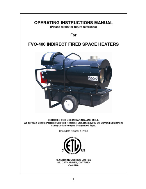
OPERATING INSTRUCTIONS MANUAL(Please retain for future reference)ForFVO-400 INDIRECT FIRED SPACE HEATERSCERTIFIED FOR USE IN CANADA AND U.S.A.As per CSA B140.8 Portable Oil Fired Heaters / CSA B140.02003 Oil Burning EquipmentConstruction Heaters Unattended Type.Issue date October 1, 2008FLAGRO INDUSTRIES LIMITEDST. CATHARINES, ONTARIOCANADAGENERAL HAZARD WARNING:FAILURE TO COMPLY WITH THE PRECAUTIONS AND INSTRUCTIONS PROVIDED WITH THIS HEATER, CAN RESULT IN DEATH, SERIOUS BODILY INJURY AND PROPERTY LOSS OR DAMAGE FROM HAZARDS OF FIRE, EXPLOSION, BURN, ASPHYXIATION, CARBON MONOXIDE POISONING, AND/OR ELECTRICAL SHOCK.ONLY PERSONS WHO CAN UNDERSTAND AND FOLLOW THE INSTRUCTIONS SHOULD USE OR SERVICE THIS HEATER.IF YOU NEED ASSISTANCE OR HEATER INFORMATION SUCH AS AN INSTRUCTIONS MANUAL, LABELS, ETC. CONTACT THE MANUFACTURER.WARNING:FIRE, BURN, INHALATION, AND EXPLOSION HAZARD. KEEP SOLID COMBUSTIBLES, SUCH AS BUILDING MATERIALS, PAPER OR CARDBOARD, A SAFE DISTANCE AWAY FROM THE HEATER AS RECOMMENDED BY THE INSTRUCTIONS. NEVER USE THE HEATER IN SPACES WHICH DO OR MAY CONTAIN VOLATILE OR AIRBORNE COMBUSTIBLES, OR PRODUCTS SUCH AS GASOLINE, SOLVENTS, PAINT THINNER, DUST PARTICLES OR UNKNOWN CHEMICALS.WARNING:NOT FOR HOME OR RECREATIONAL VEHICLE USE.WARNING:INTENDED USE IS PRIMARILY THE TEMPORARY HEATING OF BUILDINGS UNDER CONSTRUCTION, ALTERATION, REPAIR OR EMERGENCIES ONLY.ALWAYS PROVIDE ADEQUATE VENTILATION. 1 SQ. IN. OF FRESH AIR MUST BE SUPPLIED FOR EVERY 1000 BTUH OF HEAT.THIS HEATER SHALL BE INSTALLED SUCH THAT IT IS NOT DIRECTLY EXPOSED TO WATER SPRAY, AND/OR DRIPPING WATER.This heater is designed and approved for use as aconstruction heater under CSA B140.8 Portable OilFired Heaters / CSA B140.02003 Oil Burning Equipment.We cannot anticipate every use which may be madeof our heaters. CHECK WITH YOU LOCAL FIRESAFETY AUTHORITY IF YOU HAVE QUESTIONSABOUT APPLICATIONS.Other standards govern the use of fuel gases and heatproducing products in specific applications. Your localauthority can advise you about these.SPECIFICATIONSModel …………………………………………………….…. FVO-400 Input …………………………………………………….…... 390,000 btuh Fuel …………………………………………………………. No.1, No. 2,diesel orkerosene Fuel Pressure …………………………………………….... 170 psi Nozzle ………………………………………………………. 2.25 x 45B (Delavan)Ignition ………………………………………………………. Direct Spark …….……………………………………………...…. ThermostatControlAir Circulation ………………………………………………. 2500 cfm Fuel Consumption ………………………………………...... 2.75 Gal/hr Approved …………………………………………………...... cETLus listedINSTALLATION:The installation of this heater for use with No.1, No.2, Diesel or Kerosene and shall conform with local codes or, in the absence of codes, with the National Fuel Gas Code ANSI Z223.1/NFPA 54. Installation of the unit shall be in accordance with the regulations of the authorities having jurisdiction or the CSA Standard B139.CLEARANCE TO COMBUSTIBLES:TOP FRONT SIDES REAR FLUE PIPE3 ft 10 ft 3 ft 3 ft 3 ft FUEL:This heater will operate with No.1, No.2, Diesel or Kerosene.Note:No.1 Fuel Oil or Kerosene must be used fortemperatures less than –10º C (8º F).ELECTRICAL:WARNINGElectrical Grounding InstructionsThis appliance is equipped with a three-prong (grounding)plug for your protection against shock hazard and should beplugged directly into a properly grounded three-prongreceptacle.115v supply must be available. Please note that the heaterrequires 15 amps for proper operation. Ensure appropriategauge extension cord is used.• 12/3 AWG at 50 Feet• 10/3 AWG at 100 FeetFLUE PIPE: Flue pipe connection must terminate with a vertical run atleast 2ft long.The vent outlet on the heater is 6” diameter. Certified ventingmust be used at all times. Vent cap should be installed insituations where downdrafts occur. All venting mustcorrespond with the CSA B149 standard or in its absence,local codes.FV SERIES CONSTRUCTION HEATER – VENTING REQUIREMENTS1. VERTICAL FLUE TERMINATIONSDFLUE OUTLET OF HEA TER2. HORIZONTAL FLUE TERMINATIONSFLUE OUTLET OF HEAALLA - VENT TERMINATION MUST BE A MINIMUM OF 2FT HIGHER THAN ANY POINTWITHIN 10FT.B - MAXIMUM HORIZONTAL RUN IS 30FT.NOTE: 90deg ELBOW = 10ft HORIZONTAL VENT ALLOWANCE45deg ELBOW = 5ft HORIZONTAL VENT ALLOWANCEC - VENT TERMINATION IN HORIZONTAL POSITION MUST BE MINIMUM 4ft FROM ANYCOMBUSTABLE SURFACED - EXTERIOR VERTICAL VENT TERMINATION MUST BE A MINIMUM OF 2ft.NOTE: ALL VENT TERMINATIONS MUST HAVE A RAIN CAP INSTALLED AS PER LOCAL CODE REQUIREMENTS.DUCTING: Canvas heater duct with a minimum temperature handling of300 deg F. including wire reinforcement to prevent collapsing.Heater is designed for use with 2 x 12” diameter ductsequipped with pin lock couplings (FV-D12).Install ducting to outlet on the heater using pin-locks providedon collar of ducting. Ducting should be inspected periodicallyfor tearing and/or wear marks. Ducting should be stored in adry area when not in useMAINTENANCE:1. Every construction heater should be inspected before each use, and atleast annually by a qualified service person. Incorrect maintenance my result in improper operation of the heater and serious injury could occur.2. Service and Maintenance only to be performed by a qualified service person.3. The hose assemblies shall be visually inspected prior to each use of theheater. If it is evident there is excessive abrasion or wear, or the hose is cut, it must be replaced prior to the heater being put into operation. The replacement hose assembly shall be that specified by the manufacturer.4. The flow of combustion and ventilation air must not be obstructed. Be sure tocheck the fan assembly and ensure that the motor and blade are operating properly.5. Compressed air should be used to keep components free of dust and dirt buildup. Note: Do not use the compressed air inside any piping or regulator components.6. Change fuel filter insert (Part# FVO-418) once per month. Change fuel filtercartridge (Part# FVO-419) once every 6 months.7. Change oil nozzle (Part# FV-435) once per year.8. Fan Limit Switch (Part# FV-407A) should be replaced if the fan motor does notshut off after the heat exchanger has cooled down.9. The High Limit Switches (Part# FV-406 & FV-437) should be checked eachseason. These limit switches will ensure the burner shuts down if the temperature exceeds 150º F at rear of unit and 290º F at the outlet.10. Fuel tank should be drained on a regular basis by removing drain plug.11. CAUTION – Do not have any source of ignition near the heater when drainingtank.NOTE: No.1 fuel oil or kerosene is recommended for temperatures below -10º C / 8º F11. Heat Exchanger should be cleaned if smokey conditions continue even afterthe air adjustments on the burner are made.START UP INSTRUCTIONS:1. Be sure the switch in is the “OFF” position.2. Ensure electrical cord is grounded and heater is on a level surface.3. Plug in supply cord to 115V 15amp outlet.4. Move switch to “MANUAL” position for manual control.5. Move switch to “THERMOSTAT” position for thermostatic control. Please Note:1. If using Thermostat on unit, unit must be started in Thermostat position.2 When changing between manual and thermostat operation, the heatermust be left in the “OFF” position for 30 seconds to prevent the burner from locking out.3. When using a generator for electrical supply, make sure the generatoris properly grounded and generator is at a 60Hz frequency.4. In the event that a Generator is being used and the generator runs out offuel, make sure the heater switch is in the “OFF” position before restarting generator, failure to do so may damage heater.TO SHUT DOWN:1. Move switch to “OFF” position.NOTE: Fan will continue to operate after the burner shuts down. Once the unit cools down, the fan will stop.IF HEATER FAILS TO START:1. Press manual reset button at rear of burner.2. Check fuel level. There must be 2-4 gallons of fuel in the tank for theheater to start properly.3. Make sure there are no air locks in fuel lines or filter.4. Ensure proper power supply and extension cord is being used.5. Check for dirty fuel filter or blocked fuel supply line.6. Check burner nozzle assembly.NOTE: IF THE BURNER HAS BEEN RESET SEVERAL TIMES THERE MAY BE AN ACCUMULATION OF OIL IN THE CHAMBER! DO NOT CONTINUE TO TRY AND START THE HEATER!DRAIN OIL FROM HEAT EXCHANGER USING DRAIN HOLE AT FRONT OF HEAT EXCHANGER FOR 15-20 MINUTES BEFORE ATTEMPTING TO RELIGHT. LET REMAINING EXCESS OIL BURN OFF BEFORE CHECKING COMBUSTION OF UNIT.SAFE OPERATION PRECAUTIONS:1. Do not fill fuel tank while heater is operation.2. Do not attempt to start heater if excess oil remains in the heatexchanger.3. Use switch to shut down the heater. Do not try to shut down the heaterby unplugging the electrical cord.4. Do not plug anything other that the thermostat into the “Thermostat”plug.5. Do not use any fuel other that those listed on rating plate.6. Follow electrical requirements shown on rating plate and/or Electricalrequirements section of this manual.7. Before removing any guards or performing any maintenance, be surethat the main power supply is disconnected.COMBUSTION AIR ADJUSTMENTS:NOTE: Proper combustion air adjustment must be achieved using a certified combustion analyzer and smoke tester to ensure completecombustion.The air adjustment should be made to achieve 10% CO2and No. 1 or “trace” smoke. (Bacharach Scale)SETTING THE AIR ADJUSTMENT PLATEA) Regulation of thecombustion air flow is madeby adjustment of the manualAIR ADJUSTMENT PLATE(1) after loosening the FIXINGSCREWS (2 & 3). The initialsetting of the air adjustmentplate should be madeaccording to Column 5 in theBurner Set-up Chart.B) The proper number on themanual AIR ADJUSTMENTPLATE (1) should line up withthe SETTING INDICATOR (4)on the fan housing cover.Once set, the air adjustmentplate should be secured inplace by tightening SCREWS2 and 3.C) The final position of the airadjustment plate will vary on each installation. Use instruments to establish the proper settings for maximum COand a smoke reading of zero.2NOTE: Variations in flue gas, smoke, COand temperature readings may be2experienced when the burner cover is put in place. Therefore, the burner cover must be in place when making the final combustion instrument readings, to ensure proper test results.BURNER SET-UP CHART1 2 3 4 5ACTUAL FIRING RATE± 5%NOZZLESIZEPUMP PRESSUREGPH GPH PSI BAR TURBULATORSETTINGAIRDAMPERSETTING2.75 2.25 x 45°150 10 54 - 6* Note – Air damper setting is typically set at 4 for operation in coldertemperatures. A combustion analyzer should always be used when setting the the burner.TEMPERATURE FEELER GAUGE ADJUSTMENT(ATTACHED TO FAN SWITCH)The temperature feeler gauge is required to be always touching the heater exchanger.The temperature feeler gauge controls the air flow over the fan switch, which eliminates any unnecessary fan cycling. The temperature feeler gauge can be adjusted for different outside temperatures, by rotating the location of the temperature feeler gauge holes. This will provide maximum performance of the unit in different applications.If supply air is warm (-5º C, indoor application):Turn the temperature feeler gauge so that the holes are parallel with the heat exchanger. This will help the fan switch to remain cool and not overheat. See following:If supply air is cold (under -5ºC):Turn the temperature feeler gauge so that the holes are closed off as the air goes over the heat exchanger. This will reduce fan cycling and the unit from shutting down. See following:In extreme cold conditions, cover the holes on the temperature feeler gauge using foil tape. Ensure that the temperature feeler gauge is readjusted for warmer weather conditions. Failure to do so may result in burning out fan switches- notcovered under warranty.ELECTRICAL CONNECTIONSIt is advisable to leave the control box off the sub-base while completing the electrical connections to the burner.The burner may be controlled using either a DIRECT LINE VOLTAGE control circuit (120V AC 60 cycle) OR a LOW VOLTAGE control (24V AC 60 cycle) using a R8038A Honeywell switching relay or equivalent.Using the appropriate diagram below, make electrical connections to the burner. All wiring must be done in accordance with existing electrical codes, both national and local.When all electrical connections have been made, the control box may be put back in place on the sub-base.WARNING: DO NOT activate burner until proper oil line connections have been made, or failure of the pump shaft seal may occur.APPLICATION FIELD WIRINGREMOTE SENSING OF SAFETY LOCKOUT: The SAFETY SWITCH in the 530SE CONTROL BOX is equipped with a contact allowing remote sensing of burner lockout. The electrical connection is made at terminal 4 (●) on the SUB-BASE. Should lockout occur the 530SE CONTROL BOX will supply a power source of 120Vac to the connection terminal. The maximum allowable current draw on this terminal (4) is 1 Amp.WARNING: If a neutral or ground lead is attached to this terminal, the CONTROL BOX on the burner will be damaged should lockoutoccur.INSERTION / REMOVAL OF DRAWER ASSEMBLYA) To remove drawer assembly, loosen SCREW (3), then unplug CONTROLBOX (1) by carefully pulling it back and then up.B) Remove the AIR TUBE COVER PLATE (5) by loosening the two retainingSCREWS (4).C) Loosen SCREW (2), and then slide the complete drawer assembly out of thecombustion head as shown.D) To insert drawer assembly, reverse the procedure in items A to C above, andthen attach fuel line to the pump.NOZZLE PLACEMENTA) Remove the NOZZLE ADAPTER (2) from the DRAWER ASSEMBLY byloosening the SCREW (1).B) Insert the proper NOZZLE into the NOZZLE ADAPTER and tighten securely(Do not over tighten).C) Replace adapter, with nozzle installed, into drawer assembly and secure withscrew (1).ELECTRODE SETTINGTURBULATOR SETTINGA) Loosen NUT (1), then turn SCREW (2) until the INDEX MARKER (3) is alignedwith the correct index number as per the Burner Set-up chart, on page 12.B) Retighten the RETAINING NUT (1)NOTE: Zero and five are scale indicators only. From left to right, the first line is5 and the last line 0.OIL LINE CONNECTIONSNote:Pump pressure must be set at time of burner start-up. A pressure gauge is attached to the PRESSURE PORT (8) for pressure readings. Two PIPE CONNECTORS (5) are supplied with the burner for connection to either a single or a two-pipe system. Also supplied are two ADAPTORS (3), two female 1/4” NPT, to adapt oil lines to burner pipe connectors. All pump port threads are British Parallel Thread design. Direct connection of NPT threads to the pump will damage the pump body. Riello manometers and vacuum gauges do not require any adaptors, and can be safely connected to the pump ports. An NPT (metric) adapter must be used when connecting other gauge models.。
柴油热水器安装和操作指南说明书

Publication No. TRDV-40P/N 432750 Printed in U.S.A. 916DIRECT VENT OIL-FIRED WATER BOILER/NO. 2 OILTRDV SeriesREAD AND SAVE THESE INSTRUCTIONS FOR REFERENCE.Standard working pressure 30 psi water.All boilers hydrostatically tested — A.S.M.E.*For forced hot water heating systems where the boiler and all piping are located within the area to be heated, the boiler may be selected on the basis of gross D.O.E. capacity output. The net AHRI output ratings shown are based on an allowance for piping and pickup of 1.15 (water). D.O.E. capacity gross output is divided by the allowance to obtain net rating. The manufacturer should be consulted before selecting a boiler for unusual piping and pickup requirements such as intermittent system operation, extensive piping, etc.Tappings and OpeningsDimensionsRatings†Ratings apply to the use of light oil at 140,000 Btu per gallon.**TRDV-30-0.85 complies with Energy Star 3.0Figure 1Figure 2All venting kits must be double wall construction for the flue gas piping. Flex-L and Field Controls are the two approved manufacturers for venting kits.When installing the vent kits the manufacturers instructions must be fol-lowed.SEE TRDV VENTING INSTALLATION INSTRUCTIONS PUBLICATION NO. TRDV40-V .I NSTALLING WATER TRIMNotes: Jacket must be installed on boiler units prior to installation of trim.I. WA TER BOILER TRIM, see page 2 for tapping locations, and figures 1 and 2 for illustration of water boiler.A.Pressure- temperature - Altitude gauge — use tapping no. 6.B.High temperature limit — use tapping no. 7.C.Operating control (if used) — use tapping no. 7.D.Water relief valve — use tapping no. 3, piped full size to boiler.E.Automatic air vent or compression tank tappings — ifused, install in tapping no. 2.F .Combustion safety control — mounted on burner.PIPINGIMPORTANT:Boilers are to be used with closed system. Any application that uses steam or water from system, causes the introduction of a frequent supply of fresh water into the boiler. This will cause damage to the e of heat exchangers will prevent this damage.PIPING FOR WATER UNITSNOTE: On knock down boiler only, jacket may be installed after supply and return piping connection, but must be installed prior to adding trim.I. CIRCULA TING SYSTEMA.FORCED CIRCULA TION hot water heating system: Use the toptapping as supply tapping, and use the front or rear bottom tappings for the return.B. A FLOW CONTROL VAL VE (See figure 4) will prevent gravitycirculation and usually is required when tankless heater is installed.Figure 4. Air Eliminating SystemFigure 3. Typical InstallationVOLUME OF WATER IN STANDARD PIPE OR TUBEFigure 5. Air Collecting SystemFigure 6. Recommended Piping to Tankless HeaterCLEANING AND FILLING A NEW WATER BOILER I. BEFORE FILLING WA TER BOILERA.Check burner to be certain it is ready for firing. DO NOT FIREinto an empty boiler.B.Be prepared to heat raw water to at least 180°F . as soon as it isintroduced into the boiler. This procedure will remove dissolved, corrosive gases.C.Provide drain line, with valve, from boiler. Use a bottom tapping.Line and drain must be suitable for handling caustic solution.II. CLEANING WA TER BOILER SYSTEMA.Prepare a boil-out solution of sodium hydroxide (caustic soda) ortri-sodium phosphate.NOTE: Use caution in handling chemicals. Caustic soda is harmful to skin, eyes and clothing.1.Proportions: 1 lb. of either chemical per 50 gallons of sys-tem water.2.Stir chemical in water until dissolved and pour into the boilerthrough a top tapping. Replace plug.B.Fill the entire system with water.C.Start the burner, using the start-up procedure.D.Circulate the water through the entire system.E.Vent the system, including the radiation.F .Allow boiler water to reach operating temperature, if possible.G.Continue to circulate the water for a few hours.H.Shut off the burner.I.With CAUTION, drain the boiler solution to a safe location. DONOT LEAVE SOLUTION SITTING IN SYSTEM OVER 2 HOURS.J.Wash the water side of the boiler thoroughly using a high pres-sure water stream. Fill and drain the boiler several times.III. TREA TING WA TER FOR CORROSION CONTROL(This is not scale control)A.Prepare a solution of sodium chromate .Proportions: 6 oz. per 50 gallons of system water.B.Stir chemical into water until dissolved and pour into the boilerthrough a top tapping. Replace plug.IV . FILLING AND VENTING THE WA TER BOILERA.Refill the system with fresh water.B.Bring water temperature to at least 180° F . promptly.C.Circulate water through entire system.D.Vent the system, including the radiation.E.The boiler is now ready to be put into service or on standby.F .If brand-name air-control devices are used, venting instructionsfurnished with the devices should be followed.V .SAFETY CHECK FOR CONTROL SYSTEMHigh limit control test: Set thermostat high enough for boiler water temperature to reach high limit control setting. When this tempera-ture is reached, the high limit switch should open, and the burner should shut off automatically. If the high limit does not operate to shut off the burner, the high limit or the wiring is faulty. Repair or replace immediately.Wiring to the boiler must come through an emergency power isolation switch with a clearly marked red switch plate. This switch should belocated so that it is apparent to the homeowner when entering the base-ment or other boiler area. The homeowner should be made familiar with operating the toggle to provide or stop the power to the boiler.ADJUSTING SETTINGSTo discourage unauthorized changing of Aquastat settings, a procedureto enter the ADJUSTMENT mode is required. To enter the ADJUST-MENT mode, press the UP , DOWN, and I buttons simultaneously forthree seconds. Press the I button until the feature requiring adjustment is displayed:. HL_ . High Limit.. LL_ . Low Limit. (L7224 only). Ldf . Low Limit Differential. (L7224 only). °F . °C..ELL_ External Low Limit (L7248L only)Then press the UP and/or DOWN buttons to move the set point to the desired value, to change between ˚F and C˚, or to enable (On) or dis-able (Off) the External Low Limit. After 60 seconds without any button inputs, the control will automatically return to the RUN mode.DISPLAYIn the RUN mode, the Aquastat will flash .bt. (boiler temp) followed by the temperature (i.e., 220), followed by °F or °C.To read boiler settings, press the I key to read the parameter of interest.For example, press I High Limit(HL) is displayed, followed by a three-digit number, i.e., 220, followed by°F or °C. Pressing the I button again (on L7224 models) will display the Low Limit (LL) followed by a three-digit number and the corresponding degree designator.After approximately 60 seconds without any key presses, the display will enter a dim display mode. To return to the bright display mode, simply press any key.DESCRIPTION Boiler Temperature –High Limit –Low Limit –Low Limit Differential –Local Thermostat Status –Enviracom Thermostat Status –Error Code –Degrees Fahrenheit –Degrees Celsius –aWarnings are generated to enunciate the system is not operating optimally, but the Aquastat is still operating and maintaining boiler temperature. In the instance where an Outdoor Reset Module is used, the warnings may indicate a reset curve setting error one or more features is not running optimally, and the Aquastat is reverting to default settings or has stopped running the Outdoor Reset algorithms. The warnings are cleared when the issue(s) is resolved.b To clear Err 8 condition, depress and hold all three user keys simultaneously for 60 seconds. Err 8 condition clears and display returns to normal. Err 8 condition is designed to catch welded relays on the Aquastat and will normally only occur near end of life for the control. If Err 8 condition has occurred early in the controls life, be sure to check for voltage feedback to B1 when B1 should be off and check current draw on b terminal to be sure oil burner is not draw-ing excessive current. Err 8 condition will keep repeating if B1 fault is not cleared.Aquastat no i t c A /e s u a C e d o C r o r r E EnviraCOM Alarm 81.r o s n e s r e t a w k c e h c ;t l u a f r o s n e s t a t s a u q A 1r r E 81.g n i r i w ™M O C a r i v n E k c e h c ;t l u a f M O C E 2r r E Err3Excessive electrical noise or frequency out of range. Hardware fault; replace controller.18, 5846.e g a t l o v /g n i r i w 1B k c e h c ;t l u a f 1B 4r r E 95.c a V 011 ,2L -1L k c e h c ;e n i L w o L 5r r E Err6a29.e s uf e c a l p e r ,s e r i w M O C E k c e h c ;e s u F :g n i n r a W A /N .s e u l a v t l u a f e d o t t e s e r ;f d L ,f d H ,L L ,L H ,M O R P E E :g n i n r a W 7r r E Err 8b Repeated B1 fault (voltage present at B1 when output is turned off); check B1 wiring/voltage.25Err9a Warning: Outdoor Reset System failure; communication to Outdoor Reset Module lost,Outdoor Reset Module failure, multiple outdoor temperature sensors detected on the bus, or outdoor temperature sensor failure. Check EnviraCOM wiring (1, 2, 3), check sensor wiring.50, 53, 149Err 10a Warning: Boost Failure; Boost Mode active at least once per cycle for the last 60 consecutive cycles. Check Outdoor Reset curve settings.150Err 11aDHW Module/Sensor failure; communication to DHW Module lost, DHW Module failure, or temperature sensor failure. Check EnviraCOM wiring (1, 2, 3), check sensor wiring.146, 147, 148Basic Module Wiring (less circulator)Model BF-5 Electrode SettingTurbulator locationPicture 1Turbulator SettingFigure 8Proper Insertion into Combustion ChamberTURBULATOR SETTING1.Loosen nut, 1, then turn the screw, 2, until the index marker, 3, is aligned with the correct index number.2. Retighten the retaining nut, 1.The numbers on the casting are there to denote the high and low end of the scale – For Model BF-5, zero and four are scale indicators only. From left to right, the first line is 4 and the last line is 0.The air/oil ratio depends on accurate setting of the turbulator disc and air damper.Be careful when making this adjustment as an incorrect setting will result in an unsatisfactory operation.See figure 8 & 9.Figure 7Figure 93211/4”1Picture 2. Air Damper Location3CARE AND MAINTENANCEclean if necessary.3.Inspect the chimney for soot, debris and other unsafe condi-tions of the chimney and take the necessary action.4.Remove the flue collector by first removing the top jacket panel.The flue collector is held in place by a 10-32 Hex NutsRemove the Hex Nuts and carefully remove the flue collector.T ry not to disturb the seal under the flue collector.5.When necessary to clean the combustion chamber you mustfirst CLOSE the suction valve (and return valve if two pipe).Then disconnect the oil lines from the burner. The flexible elec-tric conduit connected from the junction box on the boiler to theburner via a plastic connector must be disconnected from theburner by grasping the plastic half of the connector closest tothe flexible conduit and gently pulling it in the direction of theconduit until it is disconnected. Remove the single 3/8-16 hexhead screw on the LEFT side of the swinging door. Y ou willneed a 9/16” drive socket. Open the door to completely exposethe combustion chamber for thorough cleaning and for inspec-tion of target wall, blanket (provided in certain models; see rat-ing plate), main cast iron burner door insulation and burnerdoor fiberglass sealing rope. If combustion chamber partsabove are badly deteriorated then replace with original factoryparts available at your distributor.III.OIL BURNERAll service to the oil burner, oil filter, oil strainers, etc., should be performed by a professionally trained service person.Inspect and clean annually and following any period of improper operation. Recheck and adjust settings as specified for burner model and nozzle size. Set burner air and draft regulator, using test instru-ments to obtain recommended CO 2and draft without smoke.Refer to page 5.IV .GENERAL MAINTENANCEThese operations are recommended to be performed at regular intervals:A.BOILER HEA TING SURFACES: clean off all coatings found. Reseal covers.B.BOILER CONTROLS: check contacts, settings, correct functioning.C.PIPING: check piping and accessories for leaks.D.CHIMNEY or STUB VENT and BREECHING: check for obstruc-tions and leaks.BUSTION AIR TO BURNER: check for continued POSITIVE supply of air as required. Air needs are greatest in coldest weather. Refer to AIR SUPPL Y , page 3.F .WA TER SYSTEM: check1.System to be full of water and pressure to remain stable(between 12 psi and 25 psi).2.Air-control system: noise and air binding in radiation shouldnot occur.3.Water lines: slightest leaks should be corrected.4.Low water cut-off, for operation (see instructions furnishedwith unit). See page 9.G.BOILER ROOM AIR SUPPL Y: air vents terminal should be open and free of obstruction. See page 3.† A flue brush (2-1/4" dia.) is supplied with boiler. Replacements are available from dealer or hardware stores.。
柴油空气加热器操作说明
柴油空气加热器操作说明柴油空气加热器是一种用于车辆或建筑设备的重要辅助设备,能够提供额外的暖气效果,特别是在寒冷的天气条件下。
正确操作柴油空气加热器对保障设备运转安全、延长使用寿命至关重要。
下面将详细介绍柴油空气加热器的操作说明。
一、检查设备运行状态在使用柴油空气加热器之前,首先要检查设备的运行状态,确保设备处于正常工作状态。
检查项目包括但不限于:设备是否有明显损坏,连接是否完好,油箱中是否有足够的燃油等。
二、启动柴油空气加热器启动柴油空气加热器前,需要按照正确的操作流程进行。
首先,打开设备的电源开关,然后根据设备的操作说明进行启动操作。
在启动过程中,要保持设备周围的通风良好,确保安全。
三、设置加热温度和时间根据实际需要,设置柴油空气加热器的加热温度和时间。
一般情况下,根据环境温度来设定加热温度,时间可以根据需要来调整。
在设定完毕后,等待设备加热至设定温度即可。
四、监控加热器运行情况在柴油空气加热器运行过程中,需要不时地监控设备的运行情况,确保设备正常工作。
特别是在初始使用或长时间未使用后,要多加留意设备的运行状况,以免出现故障或安全问题。
五、关闭加热器在使用完毕或者不再需要加热时,应正确关闭柴油空气加热器。
首先,将加热温度和时间设定为最低,然后关闭设备的电源开关,等待设备冷却后再进行存放或其他操作。
六、保养与维护定期对柴油空气加热器进行保养与维护非常重要。
包括清洁设备表面、更换滤芯、加注燃油等。
这些保养措施能够延长设备的使用寿命,提高设备的性能。
通过正确的操作柴油空气加热器,可以确保设备的安全运行,提高设备的使用效率,同时也能够减少维修和更换成本。
希望以上操作说明能够帮助您正确地操作柴油空气加热器,提高工作效率和安全性。
YQB-02加热型使用说明

YQB-02加热型使用说明
YQB-02加热型车载柴暖基本概念:柴油泵把柴油从油箱内吸出,送至燃烧室内由点火塞把混合气体引燃,燃烧室内柴油点燃产生的废气由废气口排出,燃烧室表面是铝合金型材料含有排热板翅式,传热快。
离心风机立即冲着燃烧室吹风就可以把暖风送出去了,还可以用以冬天道路拥堵或停车时的供暖,行车时也能正常使用,只需将此柴暖加热器开启就可以,减少了整车燃油成本费。
YQB-02加热型车载柴暖加热器详细介绍:柴暖驻车加热器别名车辆柴暖、车辆柴油火炉,适用于严寒地方的柴油车发动机预热和驾驶室取暖,合理的解决了汽车发动机因天气寒冷造成的无法启动以及驾驶室取暖等难题,维护了汽车发动机,营造了温暖舒适的驾乘环境。
YQB-02加热型采用高质配件,国内领先技术,具有高低压自动保护功能,可根据使用场景自由选择配件,过热保护功能让用户使用更放心,不惧高原等恶劣天气均可正常使用。
柴暖加热器使用说明

柴暖加热器使用说明柴暖加热器是一种传统的取暖设备,具有环保、经济、安全等诸多优点。
在寒冷的冬季,使用柴暖加热器可以为家庭提供温暖的居住环境,同时也可以帮助节省能源。
但是,由于柴暖加热器使用时需要注意一些安全事项,因此在使用前必须详细了解其使用说明。
一、柴暖加热器的种类和特点柴暖加热器的种类繁多,常见的有炉灶式、壁挂式、立式等多种形式。
炉灶式柴暖加热器一般由炉体、烟道、炉门、炉膛等部件组成,适用于家庭取暖、烹饪等多种用途。
壁挂式柴暖加热器一般安装在墙上,不占用室内空间,适用于小型房屋、公寓等场所。
立式柴暖加热器则适用于大型房屋、办公场所等需要大面积取暖的场合。
柴暖加热器的特点主要有以下几点:1.环保:柴暖加热器使用的燃料为柴火,不会产生有害气体和污染物,对环境无污染。
2.经济:柴暖加热器使用的燃料价格较低,使用成本较低。
3.安全:柴暖加热器使用的燃料为固体燃料,不会泄漏燃气,使用安全可靠。
二、柴暖加热器的使用方法1.准备燃料:柴暖加热器使用的燃料为柴火,使用前需准备好干燥的柴火。
2.点燃燃料:将柴火放入炉膛中,点燃火种,注意安全。
3.调节火力:柴暖加热器的火力大小可以通过调节燃料的投放量和燃烧的氧气量来实现。
4.注意通风:柴暖加热器燃烧时会产生一定的烟雾和二氧化碳等有害气体,因此要保持室内通风。
5.定时清理:柴暖加热器使用一段时间后,炉膛内会积累一定的灰渣,需要定时清理,以确保其正常运转。
三、柴暖加热器的安全注意事项1.使用干燥的柴火,避免使用湿润的柴火,以免产生大量的烟雾和有害气体。
2.使用前检查燃烧室和烟道是否清洁,如有积灰应及时清理。
3.使用时要保持室内通风,避免烟雾和有害气体积聚。
4.注意火源安全,避免与易燃物接触,避免使用易燃气体点火。
5.定期检查和维护柴暖加热器,确保其正常运转和安全使用。
四、柴暖加热器的维护保养1.定期清理炉膛和烟道,避免积灰过多影响燃烧效果。
2.定期更换炉膛内的隔热材料,避免炉膛内温度过高导致事故发生。
柴油燃料热水器产品说明书
50JP-C1SB© 1998 Carrier Corporation • Syracuse, New York 13221Form 50JP-C1SB NewPrinted in U.S.A.7-98Catalog No. 015-03550JP034, 044, 054, 064SINGLE-PACKAGE COOLING UNITSEXTENDED CHASSISCONSTANT VOLUME/VARIABLE VOLUME PRODUCT INTEGRATED CONTROLSCARRIER COMFORT NETWORK COMPATIBLEFACTORY-INSTALLED OPTIONALELECTRIC HEAT50 Hz– PERFORMANCE DATA – TYPICAL FIELD WIRING– CERTIFIED DIMENSION PRINTS – CERTIFIED ROOF CURBDIMENSION PRINTS50JP034, 044, 054, 064SINGLE-PACKAGE COOLING UNITS,EXTENDED CHASSISPRODUCT INTEGRA TED CONTROLS50JPDESCRIPTION50JP units are completely packaged, pre-wired, and precharged electric cooling/heating or cooling only units with PRODUCT INTEGRA TED CONTROLS.50JP units are built for bottom supply and return applications. Their waterproof construction makes them ideally suited for installation on the accessory roof curb.Units are either CONSTANT VOLUME or V ARIABLE AIR VOLUME depending on the factory-installed op-tions selected.Units include space and coil tracks downstream of evaporator for field or factory installation of auxiliary devices.ADDITIONAL CONTROL FUNCTIONSA V AILABLE THROUGH FACTORY-INSTALLED “OPTIONS MODULE”Provides a discrete output with occupancy control for use as specified by the customer.Controls a field installed humidifier using a 4 to 20 mA or 2-stage output. Requires accessory humidity sensor.Smoke Control functions (Pressurization, Evacuation, Smoke Purge, and Fire Shutdown) are provided through software. Terminals are provided to inter-face with field supplied smoke/fire panel.Provides a 4 to 20 mA output to direct or reverse proportional hot water con-trol valve for field supplied hydronic heating coil. Requires a field supplied freezestat to protect coil.Factory installed suction and discharge pressure transducers and suction tem-perature thermistors allow remote monitoring of these parameters and super-heat to provide enhanced remote diagnostics.Differential enthalpy control can be provided using field installed accessory humidity sensors.Economizer control field configurable to:–Maintain a minimum economizer set point position,OR–Maintain the minimum economizer position based on input from an IAQ sensor (field supplied 0 to 10 volt),OR–Maintain a constant airflow of outdoor air intake (Requires accessory Out-door Air CFM package),OR–Look at all three above and maintain minimum economizer position based on the dominant parameter.PRODUCT INTEGRATED CONTROL FEATURES STANDARD CONTROL FUNCTIONSUnit compatible with CARRIER COMFORT NETWORK or stand alone operation.Constant V olume or Variable Air V olume control.Four to six stages of compressor unloading possible.Supply fan control based on occupancy schedule using 365-day electronic time clock with holiday scheduling.Time schedule override through the space temperature sensor provided with the unit.Compatible with 37H and 45 Series PIC terminals to form a Digital Air Vol-ume system (DAV).Building pressurization control in conjunction with modulating power ex-haust option.Supply duct static pressure controlled through inlet guide vanes or factory supplied inverter.Head pressure control to -29˚ C (-20˚ F). Head pressure controlled by satu-rated condensing temperature, low ambient control utilizes Motormaster® II fan cycling.Lead-lag compressor control to even out run time.Self-diagnostic run test confirms control and component operation at unit commissioning. Self-diagnostic troubleshooting codes indicate the reason unit tripped to expedite unit repair. Codes expand to English Text. Control of a two-speed supply fan motor on CV applications. (Two-speed motor available on Special Order.)Building Purge Mode flushes building interior with outdoor air to remove contaminants before occupancy.Adaptive Optimal Start minimizes the amount of time and energy required before entering the occupied mode.Unoccupied Mode Free Cooling - units with optional economizer will utilize free cooling whenever possible to maintain the unoccupied set point.Input/Output of data and monitoring of alarms can be done remotely using Building Supervisor, or at the unit using the accessory HSIO module. Delayed Mechanical Cooling - units with optional economizer will utilize cooling to cool the space 3 degrees below the occupied set point to delay the need for mechanical cooling.:e t aD:s e d e s r e p u S:v eR :EMANBOJ:NO I TACOL:REYUB#.O.PREYUB#RE I RRAC:REBMUNT I NU:REBMUNLEDOM:YBDE IF I TRECATADECNAMROFREP:ETAD23UNIT FEATURESLarge hinged access doors.Units are rated in accordance with ARI Standard 360 (U.S.A. Standard).115-volt and 24-volt control circuit.Semi-hermetic Carrier compressors.Dual refrigeration circuits.Crankcase heaters.Compressor protection includes high and low pressure cutouts.Manual adjustable outside air intake for up to 25% outside air.Single low rpm supply fan with 51 mm (2 in.) deflection springs under fan sled.High efficiency indoor motors. (supply and exhaust)Tuf-Skin Rx anti-microbial insulation.Sloped condensate pan.Cabinet made of prepainted galvanized steel.Evaporator-fan motors are protected by circuit breakers.Condenser-fan motors are internally protected.Single-point electric service entry.Circuit breaker protection for all power components.Lifting lugs.51 mm (2in.) disposable-type return air filters.ELECTRICAL DATAPower Supply to Unit ______________________ V olts _____________________ Phase _____________________ Hertz Minimum Circuit Amps ____________________________ Maximum Fuse Amps _____________________________OPTIONS AND ACCESSORIESFACTORY-INSTALLED OPTIONS u Control Options Module (PSIO2)u Pleated Filters (30%) 51 mm (2 in.)u Bag Filters with Prefilters (90%)u Inlet Guide Vanes or V ariable Frequency Driveu Economizer with Low Leak Dampers and Spring Return Motor u Copper Condenser Coil u Precoated A1 Condenser Coils u Hot Gas Bypass u Barometric Reliefu Modulating Power Exhaustu Electric Heat ____________ kWFIELD-INSTALLED ACCESSORIESu Roof Curb with Full Perimeter Support (30, 40 ton)u Roof Curb with Condenser and Support (50, 60 ton)u Roof Curb to Enclose the Condenser Section (50, 60 ton)u Outdoor Air Cfm Package u Condenser Coil Guardu Space Sensor with Set Point Adjustment (T-56)u Differential Enthalpy Control SensoruHSIO Keypad and Display Module (required for initial start-up)u Barometric Relief Packageu Control Options Module (PSIO2)u Pressure Transducers and Thermistors u IAQ Sensoru Relative Humidity SensorUnit Operating Weight _________________________________________Indoor Entering Air db __________________ wb ___________________COOLINGGross Total Cap. ___________ Condenser Air Temp ________________Gross Sensible Capacity ________________________________________Compressor Power Input _______________________________________Indoor Fan Motor Size _________________________________________Exhaust Fan Motor Size ________________________________________PERFORMANCE DATAAirflow ______________ External Static Pressure _________________Curb W eight _________________________________________________HEATINGHeating Capacity Total _________________________________________Stage 1_____________________________________________________Stage 2_____________________________________________________x。
柴油热水器说明书
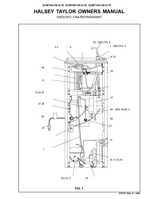
HALSEY TAYLOR OWNERS MANUALUSES HFC-134A REFRIGERANT30 - SEE FIG. 52,348,9,10,1120FIG. 197037C (Rev. A - 4/98)F IG . 2E = I N S U R E P R O P E R V E N T I L A T I O N B Y M A I N T A I N I N G 4" (102m m ) (M I N .) C L E A R A N C EF R O M C A B I N E T L O U V E R S T O W A L L .A S EG U R E U N A V E N T I L A C I ÓN A D E C U A D A M A N T E N I E N D O U N E S P A C I O E 4" (102m m ) (M ÍN .) D EH O L G U R A E N T R E L A R E JI L L A D E V E N T I L A C I ÓN D E L M U E B L E Y L A P A R E D A S S U R E Z -V O U S U N E B O N N E V E N T I L A T I O N E N G A R D A N T 4" (102m m ) (M I N .) E N T R E L E S ÉV E N T S D E L E N C E I N T E E T L E M U R .F = P O W E R C O R D 4' (1219m m ) L O N G C A B L E E L ÉC T R I C O D E 4' (1219m m ) P I E , D E L A R G O C O R D O N D A L I M E N T A T I O N 4' (1219m m )G = W A L L S C R E W H O L E S A G UJ E R O S D E T O R N I L L O S D E P A R E D T R O U S D E V I S D U M U R H = 2 X 4 B L O CK I N G BL O Q U E O D E 2 X 4B L O C 2 X 4F I N I S H E D F L O O R P I S O A C A B A D O P L A N C H E R F I N IL E G E N D /L E Y E N D A /L ÉG E N D E A = R E C O M M E N D E D W A T E R S U P P L Y L O C A T I O N 3/8 O .D . U N P L A T E D C O P P E R T U B E C O N N E C T S T U B O U T 1-1/2 I N . (38m m )F R O M W A L L S H U T O F F B Y O T H E R S S E R E C O M I E N D A U B I C A R E L T U B O C O R T O D E C O N E X I ÓN A L T U B O D E C O B R E S I N C H A P A R D E 3/8" D E D I ÁM . E X T . A 1-1/2"(38 m m ) F U E R A D E L A L L A V E D E P A S O E N L A P A R E D C O L O C A D A P O R T E R C E R O S . E M P L A C E M E N T R E C O M M A N D É D 'A L I M E N T A T I O N E N E A U P A R T U B E E N C U I V R E N O N P L A Q U É D E 3/8 P O . (9,5 m m ) D .E .C O N N E C T A N T U N E T U Y A U T E R I E D E 1-1/2 P O . (38 m m ) D E P U I S L E R O B I N E T D 'A R R ÊT F O U R N I P A R D 'A U T R E S .B = R E C O M M E N D E D L O C A T I O N F O R W A S T E O U T L E T 1-1/4 O .D . D R A I N U B I C A C I ÓN R E C O M E N D A D A P A R A E L D R E N A J E D E S A L I D A D E A G U A , D E 1¼ D E D I ÁM E T R O .E M P L A C E M E N T R E C O M M A N D É P O U R L E D R A I N D E D .E . 1-1/4" D E S O R T I E D E A U .C = 1-1/4 T R A P N O T F U R N I S H E D P U R G A D O R D E 1¼ N O P R O P O R C I O N A D O S I P H O N 1-1/4 N O N F O U R N I D = E L E C T R I C A L O U T L E T L O C A T I O N U B I C A C I ÓN D E L A T O M A D E E L E C T R I C I D A D E M P L A C E M E N T D E L A P R I S E D E C O U R A N T97037C (Rev. A - 4/98)PUSH BUTTON VALVE ADJUSTMENTFIG. 41524262523,27,28CORRECT STREAM HEIGHTFIG. 322111C 22112C 22113C 30980C 31386C 31428C 50787C 70606C 70607C 70640C 70659C 70683C 70793C 22588C12345678910111213NSPART. NO.DESCRIPTIONITEM NO.HOT TANK PARTS LISTHeater Clamping BracketHeater Clamping Bracket (thrd)Retaining BracketHeater Element & Jacket Tank & Tube Assy Hot Control Assy Washer-Spacer Drain PlugScrew 1/4-20 x 3.00" HSHC Screw #8-18 x 5/16" HHTC Belleville Washer 1/4 Union 1/4 ElbowHot T ank Mounting BracketSERVICING THE HOT CONTROL AND FUSE ASSEMBLY1. A temperature sensing non-resetable fuse in the wire is located approximately 3" (76mm) from the thermostat. The fuse is located under the retaining bracket (Item 3) in the groove on the heater element jacket (Item 4).2. The thermostat must be used with a washer-spacer (Item 7) and be centered in the heater element jacket for proper temperature control. Locate the heater element jacket about 3/4" (19mm) above the bottom of the tank.3. The heater element jacket must be fastened VERY TIGHTLY to the tank (45+/-10 inch/lbs. of torque on the mounting screw Item 9). Failure to TIGHTEN heater element jacket may cause rapid failure of the fuse assembly.10367911128134512ADJUST THIS SCREW TO ELIMINATE VALVE LEVER "FREE PLAY" OR CONTINUOUS FLOW FROM BUBBLERSTREAM HEIGHTADJUSTMENT SCREW97037C (Rev. A - 4/98)ITEM NO.PART NO.DESCRIPTION51544C 10-26399-31-64016-02705-08-64040-15018-42-59055880C 66324C66325C 66327C 35839C 35787C 35762C 31034C 31027C 19-42439-01-55035766C 45689C 45697C 66251C 66252C 10-14534-31-64010-15075-31-55031490C 10-42095-43-73070018C 40-26720-43-73066201C 66202C 66258C 66245C 19-26685-51-55015005C 26860C 26861C 26862C 50986C 61314C 55996C 40580C 3365900040596C 40597C 51543C 70921C 92712C 21591C 30010C 55832C 31397C 22588C 55913C 55885C See Color T able See Color T able See Color T ableBubbler Drain Plug Strainer Plate BasinBracket-Regulator Mounting Evaporator (4 GPH)Evaporator (8 GPH)Evaporator (14 GPH)Cold ControlCompressor Serv. Pak (4 & 8 GPH)Compressor Serv. Pak (14 GPH)Overload/Relay Assy (4 & 8 GPH)Overload/Relay Assy (14 GPH)Electrical Shield Relay CoverT ailpipe Assy (4 GPH)Precooler (8/14 GPH) Includes 55 & 56Condenser (4 & 8 GPH)Condenser (14 GPH)Cap Push Button Push Button Stem Fan Motor Fan Blade Fan Blade Nut Fan Motor Bracket Drier (4 & 8 GPH)Drier (14 GPH)Heat Exchanger (4 & 8 GPH)Heat Exchanger (14 GPH)Power CordRegulator Retaining Nut Regulator Lever Pivot BracketRegulator Retaining Bracket Regulator Holder Regulator StrainerHot Valve Assy Gasket-Body Shroud Gooseneck Lever Handle Mounting Nut Stem AssyHot T ank Switch Bracket Hot T ank T oggle Switch Flow Regulator Assy Hot T ank AssyHot T ank Mounting Bracket Adaptor-Drain W/O Holes Nut 1-1/4 Slip Joint Side Panel - Right Side Panel - Left Front PanelPlatinum (PV)Almond (AV)Slate (SV)Stnlss Stl (SS)40153624841026912C 40153624844040153624283040153634841026908C 40153634844040153634283040150744841026904C 4015074484404015074428302222 CAMDEN COURT OAK BROOK, IL 60523630.574.3500PRINTED IN U.S.A.IMPRESO EN LOS E.E.U.U.IMPRIMÉ AUX É.-U.RIGHT PANEL FRONT PANEL COLOR LEFT PANEL *INCLUDES RELAY & OVERLOAD. IF UNDER WARRANTY, REPLACE WITH SAME COMPRESSOR USED IN ORIGINAL ASSEMBLY .NOTE: All correspondence pertaining to any of the above water coolers or orders for repair parts MUST include Model No. and Serial No. of cooler, name and part number of replacement part.ITEMIZED PARTS LIST12345678*9101112131415161718192021222324252627282930313233343536373839404142434445NSWIRING DIAGRAMThis Drawing is merely for illustrating the components of the electrical system.FIG. 5333632313435。
京威牌汽车加热器使用说明书

空气加热器说明书FJH-2.5AⅡ/5AⅡ前言公司简介首先感谢您选用北京京威汽车设备有限公司加热器,我公司是有着40余年研发设计经验的加热器生产厂家。
目前公司拥有自主研发的YJH、FJH、YJP、YJ、QN共五大系列产品。
本公司是以质量第一服务至上的原则服务于社会。
FJH加热器简介特点1.低油耗高效率。
2.使用环境广,可在高原平原任意使用。
3.极寒天气好帮手,可在-41℃正常工作。
4.体积小,噪音低。
警告:1、加热器附近禁止放置任何可燃物或易燃易爆危险品,否则可能造成火灾。
2、加热器废气出口下方300mm以内不得有任何遮挡物。
废气出口温度较高,下方如有线束、橡胶管路、液压管路等不耐高温材料,容易引起火灾。
3、进行日常维护过程中,请注意察看停车时加热器下部有没有燃油渗出的痕迹。
加热器漏油有可能引起火灾。
4.严禁使用柴油以外的其他燃料。
5、如果加热器安装在室内,必须把废气全部引导至室外,并确保不得有泄漏。
如果不按此安装有可能会导致尾气中毒或窒息的危险发生。
6、关闭车辆总电源开关前,请提前3分钟以上关闭加热器。
否则会造成加热器无法延迟吹凉,机体持续高温导致加热器损坏。
7、严禁对加热器进行改造,使用非本公司的原装部件进行修理(替换)、以及采用不符合本公司规定的方法进行安装设置等。
8、禁止以拖拽线束的方式移动加热器。
对于因以上原因所造成的事故、损坏,京威公司不负赔偿责任。
目录1.产品参数----------------------------------------------------------------------------52.使用条件----------------------------------------------------------------------------53.安装指导----------------------------------------------------------------------------54.外形附图----------------------------------------------------------------------------85.安装开孔图-------------------------------------------------------------------------96.主机结构图------------------------------------------------------------------------117.安装位置图------------------------------------------------------------------------128.安装结构图------------------------------------------------------------------------139.电路原理图------------------------------------------------------------------------1410.使用须知-------------------------------------------------------------------------1511.维护/维修------------------------------------------------------------------------1612.故障代码/服务-------------------------------------------------------------17/18产品参数质量外形尺寸发热量热风排量额定功耗点火功耗耗油量单位Kg mm KW M/h W W L/h FJH-2.5AⅡ 2.7313×115×122 2.59036≤1000.3 FJH-5AⅡ 4.5388×141×150515050≤1000.6使用条件•储藏温度:-55℃至+70℃;•工作温度:-41℃至+50℃•请使用与环境温度相适宜的低温柴油,否则燃油会在油管中结腊,造成加热器无正常法工作;5℃以上-5℃以上-15℃以上-30℃以上-41℃以上0#柴油-10#柴油-20#柴油-35#柴油-50#柴油•产品使用高度:民品海拔≤3000m;军品海拔≤5500m.•正常工作车速:0-100KM/安装指导1.选择合适位置,加热器应远离震动大,易淋雨,易涉水的地方。
- 1、下载文档前请自行甄别文档内容的完整性,平台不提供额外的编辑、内容补充、找答案等附加服务。
- 2、"仅部分预览"的文档,不可在线预览部分如存在完整性等问题,可反馈申请退款(可完整预览的文档不适用该条件!)。
- 3、如文档侵犯您的权益,请联系客服反馈,我们会尽快为您处理(人工客服工作时间:9:00-18:30)。
柴油空气加热器是一种用于加热空气的设备,主要应用于柴油发电机组、工程车辆、货车、房车等场景。
本文将详细介绍柴油空气加热器的原理、结构、分类及使用注意事项。
一、柴油空气加热器原理:
柴油空气加热器通过燃烧柴油产生热量,将热量传递给空气,使空气温度升高。
其工作原理主要包括以下几个步骤:
1. 柴油喷射:柴油喷射系统将柴油以雾化形式喷入加热器燃烧室。
2. 燃烧:喷入的柴油在燃烧室内与空气混合,在高温条件下燃烧产生热量。
3. 热量传递:燃烧产生的热量通过热交换器传递给空气,使空气温度升高。
4. 热空气输出:经过加热的热空气被输送至需要加热的区域。
二、柴油空气加热器结构:
1. 燃烧室:柴油燃烧的地方,雾化柴油在此处与空气混合并燃烧。
2. 热交换器:热量传递的场所,柴油燃烧产生的热量通过热交换器传递给空气。
3. 风机:将加热后的热空气输送至需要加热的区域。
4. 柴油喷射系统:负责将柴油喷入燃烧室。
5. 控制系统:用于控制加热器的启动、运行和停止。
三、柴油空气加热器分类:
根据加热方式的不同,柴油空气加热器主要分为以下几种类型:
1. 直接加热式:柴油直接喷射至燃烧室,与空气混合燃烧产生热量。
2. 间接加热式:柴油通过热交换器加热空气,热量传递更为高效。
3. 辐射式:利用辐射原理加热空气,热量传递速度快,但安装要求较高。
四、柴油空气加热器使用注意事项:
1. 在使用柴油空气加热器时,应确保柴油品质合格,防止燃烧设备损坏。
2. 定期检查加热器部件,确保其正常工作,如发现故障应及时维修或更换。
3. 加热器运行时,确保周围环境通风良好,避免缺氧或有害气体积聚。
4. 遵循设备操作规程,不要擅自改装或拆卸加热器,以免造成安全隐患。
5. 定期清理加热器,保持其清洁,以提高热效率。