DPtech UTM2000系列统一威胁管理安装手册v1.1
DPtech UTM2000-GS-N统一威胁管理安装手册

DPtech UTM2000-GS-N统一威胁管理安装手册杭州迪普科技有限公司为客户提供全方位的技术支持。
通过杭州迪普科技有限公司代理商购买产品的用户,请直接与销售代理商联系;直接向杭州迪普科技有限公司购买产品的用户,可直接与公司联系。
杭州迪普科技有限公司地址:杭州市滨江区火炬大道581号三维大厦B座901室邮编:310053声明Copyright 2009杭州迪普科技有限公司版权所有,保留一切权利。
非经本公司书面许可,任何单位和个人不得擅自摘抄、复制本书内容的部分或全部,并不得以任何形式传播。
由于产品版本升级或其他原因,本手册内容有可能变更。
杭州迪普科技有限公司保留在没有任何通知或者提示的情况下对本手册的内容进行修改的权利。
本手册仅作为使用指导,杭州迪普科技有限公司尽全力在本手册中提供准确的信息,但是杭州迪普科技有限公司并不确保手册内容完全没有错误,本手册中的所有陈述、信息和建议也不构成任何明示或暗示的担保。
目录第1章产品介绍 1-11.1产品概述1-1 1.2DP TECH UTM2000-GS-N产品外观 1-1 1.3产品规格1-3 1.3.1存储器1-3 1.3.2外形尺寸和重量 1-3 1.3.3固定接口和槽位数 1-4 1.3.4输入电源 1-4 1.3.5工作环境 1-4第2章安装前的准备 2-12.1通用安全注意事项 2-1 2.2检查安装场所 2-1 2.2.2温度/湿度要求 2-1 2.2.3洁净度要求 2-2 2.2.4防静电要求 2-2 2.2.5抗干扰要求 2-3 2.2.6防雷击要求 2-3 2.2.7接地要求 2-3 2.2.8布线要求 2-3 2.3安装工具2-3第3章设备安装 3-13.1安装前的确认 3-1 3.2安装流程3-2 3.3安装设备到指定位置 3-2 3.3.2安装设备到工作台 3-3 3.3.3安装设备到19英寸机柜 3-4 3.4连接接地线 3-5 3.5连接接口线缆 3-6 3.5.1连接配置口线缆 3-6 3.5.2连接网络管理口 3-63.5.3连接业务口 3-7 3.6连接电源线 3-7 3.7安装后检查 3-7第4章设备启动及软件升级 4-14.1设备启动4-1 4.1.1搭建配置环境 4-1 4.1.2设备上电 4-4 4.1.3启动过程 4-5 4.2W EB默认登录方式 4-6第5章常见问题处理 5-15.1电源系统问题故障处理 5-1 5.2设备故障处理 5-1图形目录图1-1 DPtech UTM2000-GS-N前视图 1-1图1-2 DPtech UTM2000-GS-N前面板指示灯 1-3图1-3 DPtech UTM2000-GS-N后视图 1-3图3-1 设备安装流程 3-2 图3-2 安装设备于工作台 3-4图3-3 安装挂耳3-4图3-4 安装设备到机柜(为清晰起见省略了机柜) 3-4图3-5 固定设备3-5图3-6 连接接地线示意图 3-5图3-7 连接保护地线到接地排 3-6图3-8 电源线连接示意图 3-7图4-1 通过 Console口进行本地配置示意图 4-1图4-2 超级终端连接描述界面 4-1图4-3 超级终端连接使用串口设置 4-2图4-4 串口参数设置 4-3 图4-5 超级终端窗口 4-3 图4-6 终端类型设置 4-4 图4-7 Web网管登录页面 4-7表格目录表1-1 存储器规格1-3表1-2 外形尺寸和重量规格 1-3表1-3 固定接口规格 1-4 表1-4 输入电压1-4表1-5 工作环境1-4表2-1 机房温度/湿度要求 2-1表2-2 机房灰尘含量要求 2-2表2-3 机房有害气体限值 2-2表4-1 设置串接口属性 4-2第1章产品介绍1.1 产品概述DPtech UTM2000-GS-N统一威胁管理创新性地采用了“多业务并行处理引擎(MPE)”技术,在多功能开启情况下性能不受影响,能够满足防护混合威胁的安全需求。
UTM统一威胁管理操作指导

接入交换机
192.168.0.100
UTM Manager
Trust
192.168.0.0/24
需求: UTM 开启基本的防火墙功能, 同时开启防攻击、防病毒保护 以及带宽管理等深度检测功能。
36
开局准备:
1.版本是否正确? B5103及以前的版本:均为单系统版本,只有FW、VPN功能, 没有深度检测功能。 B5104及以后的版本:均为双系统版本,可以开启UTM所有 功能。 若版本不正确,开局前请务必升级到最新版本!!!
34
I-WARE基本功能配置:
1.特征库升级 2.IPS 3.AV
4.带宽管理
5.URL过滤
6.上网行为审计(结合UTM Manager)
35
配置举例:
Internet
UnTrust
G0/1:60.191.99.141
U200S
G0/0:192.168.0.1
VPN
提供远 程访问 数据的 防窃取 、防窜 改的安 全保证
入侵防御
防御最 新的安 全威胁 及恶意 攻击
防病毒
提供病 毒、蠕 虫、木 马、恶 意代码 的查杀 功能
URL过滤 应用控制 行为审计
屏蔽非 法网站 ,使用 户免受 干扰, 确保网 络健康 使用 限制 P2P/IM 应用, 保证关 键业务 的有效 带宽 对用户 的各种 上网行 为审计 、分析 、输出 报表
14
配置防火墙访问控制策略:
15
配置防火墙地址转换策略:
16
配置防火墙地址转换策略:
17
配置防火墙地址转换策略ACL:
18
配置防火墙地址转换策略ACL:
DPtech UTM2000-MA-N统一威胁管理安装手册
DPtech UTM2000-MA-N统一威胁管理安装手册杭州迪普科技有限公司为客户提供全方位的技术支持。
通过杭州迪普科技有限公司代理商购买产品的用户,请直接与销售代理商联系;直接向杭州迪普科技有限公司购买产品的用户,可直接与公司联系。
杭州迪普科技有限公司地址:杭州市滨江区火炬大道581号三维大厦B座901室邮编:310053声明Copyright 2009杭州迪普科技有限公司版权所有,保留一切权利。
非经本公司书面许可,任何单位和个人不得擅自摘抄、复制本书内容的部分或全部,并不得以任何形式传播。
由于产品版本升级或其他原因,本手册内容有可能变更。
杭州迪普科技有限公司保留在没有任何通知或者提示的情况下对本手册的内容进行修改的权利。
本手册仅作为使用指导,杭州迪普科技有限公司尽全力在本手册中提供准确的信息,但是杭州迪普科技有限公司并不确保手册内容完全没有错误,本手册中的所有陈述、信息和建议也不构成任何明示或暗示的担保。
目录第1章产品介绍 1-11.1产品概述1-1 1.2DP TECH UTM2000-MA-N产品外观 1-1 1.3产品规格1-3 1.3.1存储器1-3 1.3.2外形尺寸和重量 1-3 1.3.3固定接口和槽位数 1-4 1.3.4输入电源 1-4 1.3.5工作环境 1-4第2章安装前的准备 2-12.1通用安全注意事项 2-1 2.2检查安装场所 2-1 2.2.2温度/湿度要求 2-1 2.2.3洁净度要求 2-2 2.2.4防静电要求 2-2 2.2.5抗干扰要求 2-3 2.2.6防雷击要求 2-3 2.2.7接地要求 2-3 2.2.8布线要求 2-3 2.3安装工具2-3第3章设备安装 3-13.1安装前的确认 3-1 3.2安装流程3-2 3.3安装设备到指定位置 3-2 3.3.2安装设备到工作台 3-3 3.3.3安装设备到19英寸机柜 3-4 3.4连接接地线 3-5 3.5连接接口线缆 3-6 3.5.1连接配置口线缆 3-63.5.2连接网络管理口 3-6 3.5.3连接业务口 3-7 3.6连接电源线 3-7 3.7安装后检查 3-7第4章设备启动及软件升级 4-14.1设备启动4-1 4.1.1搭建配置环境 4-1 4.1.2设备上电 4-4 4.1.3启动过程 4-5 4.2W EB默认登录方式 4-6第5章常见问题处理 5-15.1电源系统问题故障处理 5-1 5.2设备故障处理 5-1图形目录图1-1 DPtech UTM2000-MA-N前视图 1-1图1-2 DPtech UTM2000-MA-N前面板指示灯 1-3图1-3 DPtech UTM2000-MA-N后视图 1-3图3-1 设备安装流程 3-2 图3-2 安装设备于工作台 3-4图3-3 安装挂耳3-4图3-4 安装设备到机柜(为清晰起见省略了机柜) 3-4图3-5 固定设备3-5图3-6 连接接地线示意图 3-5图3-7 连接保护地线到接地排 3-6图3-8 电源线连接示意图 3-7图4-1 通过 Console口进行本地配置示意图 4-1图4-2 超级终端连接描述界面 4-1图4-3 超级终端连接使用串口设置 4-2图4-4 串口参数设置 4-3 图4-5 超级终端窗口 4-3 图4-6 终端类型设置 4-4 图4-7 Web网管登录页面 4-7表格目录表1-1 存储器规格1-3表1-2 外形尺寸和重量规格 1-3表1-3 固定接口规格 1-4 表1-4 输入电压1-4表1-5 工作环境1-4表2-1 机房温度/湿度要求 2-1表2-2 机房灰尘含量要求 2-2表2-3 机房有害气体限值 2-2表4-1 设置串接口属性 4-2第1章产品介绍1.1 产品概述DPtech UTM2000-MA-N统一威胁管理创新性地采用了“多业务并行处理引擎(MPE)”技术,在多功能开启情况下性能不受影响,能够满足防护混合威胁的安全需求。
ProSecure Unified Threat Management (UTM) 安装指南说明书
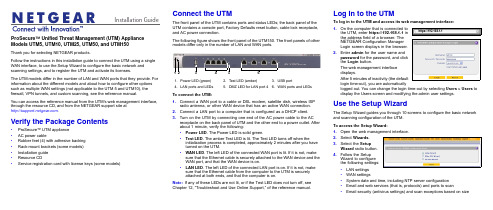
Installation Guide ProSecure™ Unified Threat Management (UTM) Appliance Models UTM5, UTM10, UTM25, UTM50, and UTM150Thank you for selecting NETGEAR products.Follow the instructions in this installation guide to connect the UTM using a single WAN interface, to use the Setup Wizard to configure the basic network and scanning settings, and to register the UTM and activate its licenses.The UTM models differ in the number of LAN and WAN ports that they provide. For information about the different models and about how to configure other options such as multiple WAN settings (not applicable to the UTM 5 and UTM10), the firewall, VPN tunnels, and custom scanning, see the reference manual.You can access the reference manual from the UTM’s web management interface, through the resource CD, and from the NETGEAR support site at.Verify the Package Contents•ProSecure™ UTM appliance•AC power cable•Rubber feet (4) with adhesive backing•Rack-mount brackets (some models)•Installation guide•Resource CD•Service registration card with license keys (some models)Connect the UTMThe front panel of the UTM contains ports and status LEDs; the back panel of theUTM contains a console port, Factory Defaults reset button, cable lock receptacle,and AC power connection.The following figure shows the front panel of the UTM150. The front panels of othermodels differ only in the number of LAN and WAN ports.To connect the UTM:1.Connect a WAN port to a cable or DSL modem, satellite dish, wireless ISPradio antenna, or other WAN device that has an active WAN connection.2.Connect a LAN port to a computer that is configured as a DHCP client.3.Turn on the UTM by connecting one end of the AC power cable to the ACreceptacle on the back panel of UTM and the other end to a power outlet. Afterabout 1 minute, verify the following:•Power LED. The Power LED is solid green.•Test LED. The amber Test LED is lit. The Test LED turns off when theinitialization process is completed, approximately 2minutes after you haveturned on the UTM.•WAN LED. The left LED of the connected WAN port is lit. If it is not, makesure that the Ethernet cable is securely attached to the WAN device and theWAN port, and that the WAN device is on.•LAN LED. The left LED of the connected LAN port is on. If it is not, makesure that the Ethernet cable from the computer to the UTM is securelyattached at both ends, and that the computer is on.Note:If any of these LEDs are not lit, or if the Test LED does not turn off, seeChapter 12, “Troubleshoot and Use Online Support,” of the reference manual.1.Power LED (green)2.Test LED (amber)B portN ports and LEDs5.DMZ LED for LAN port 46.WAN ports and LEDsLog In to the UTMTo log in to the UTM and access its web management interface:1.On the computer that is connected tothe UTM, enter https://192.168.1.1 inthe address field of a browser. TheNETGEAR Configuration ManagerLogin screen displays in the browser.2.Enter admin for the user name andpassword for the password, and clickthe Login button.The web management interfacedisplays.After 5 minutes of inactivity (the defaultlogin time-out), you are automaticallylogged out. You can change the login time-out by selecting Users > Users todisplay the Users screen and modifying the admin user settings.Use the Setup WizardThe Setup Wizard guides you through 10 screens to configure the basic networkand scanning configuration of the UTM.To access the Setup Wizard:1.Open the web management interface.2.Select Wizards.3.Select the SetupWizard radio button.4.Follow the SetupWizard to configurethe following settings:•LAN settings•WAN settings•System date and time, including NTP server configuration•Email and web services (that is, protocols) and ports to scan•Email security (antivirus settings) and scan exceptions based on sizehttps://192.168.1.1December 2012NETGEAR and the NETGEAR logo are registered trademarks of NETGEAR, Inc. in the United States and/or other countries. Other brand and product names are trademarks or registered trademarks of their respective holders. Information is subject to change without notice. © NETGEAR, Inc. All rights reserved.Intended for indoor use only in all EU member states, EFTA states, and Switzerland.•Web security (antivirus settings) and scan exceptions based on size•Web categories to be blocked•Email notification•Scan engine and signatures update settings5.Click the Apply button to save your changes.The UTM reboots. If the IP address of your computer is now on a differentsubnet, restart the computer to refresh its network settings so you can log in to the UTM again.Note:For detailed steps about how to configure the UTM by using the Setup Wizard, see Chapter 2, “Use the Setup Wizard to Provision the UTM in Your Network,” of the reference manual.Register the UTM and Activate the Licenses To receive threat management component updates and use telephone support, you need to register your UTM with NETGEAR. You might have purchased the UTM with a 1- or 3-year license. The UTM also comes with four 30-day trial licenses:•Web protection•Email protection•Support and maintenance•Application control and IPSIf your UTM is unregistered, you can use the 30-day trial period for all four types of licenses to perform the initial testing and configuration.Activating the licenses initiates their terms of use. Activate the licenses only when you are ready to start using the UTM. The 30-day trial licenses are revoked once you activate the purchased licenses.To register the UTM and activate the trial or purchased licenses:1.Make sure that the UTM has Internet access.2.Open the web management interface.3.Select Support > Registration. The Registration screen displays.4.Enter one of the license keys in the Registration Key field.plete the fields in the Customer Information and VAR Information sectionsof the screen.6.Click one of the following buttons:•Trial. Activates a trial license and registers the UTM with the NETGEARregistration and update server.•Register. Activates a purchased license and registers the UTM with theNETGEAR registration and update server.7.If necessary, repeat Step 4 and Step 6 for additional license keys.After the registration and activation are complete, the Registration screenshows the license keys and their expiration dates:Electronic Licensing OptionIf you have purchased the UTM with a 1- or 3-year license, you might be able to usethe electronic licensing option. When the UTM is connected to the Internet, youneed to enter only your customer information and optional value-added reseller(VAR) information on the Register screen but do not need to enter the licensenumbers. When you click the Register button, the UTM automatically downloadsand activates the license keys because the serial number of the UTM is linked to thelicense.If you have purchased a license from a VAR (either directly or over the web) afterpurchase of the UTM, the VAR should email you the license keys or provide them toyou in another way. To register and activate the license keys, follow the regularregistration procedure as explained in the previous section (see steps 1–7).Online Documentation and ResourcesFor extensive information about configuring and using your UTM, see the referencemanual, which you can access from or from theweb management interface.To access online documentation and resources:1.Open the web management interface.2.Select one of the following:•To view the reference manual, select Support > Documentation.•To view the product support page, select Support > Knowledge Base.Technical SupportVisit for product updates and web support.For the complete EU Declaration of Conformity, visit/app/answers/detail/a_id/11621/.NETGEAR recommends that you use only the official NETGEAR supportresources.。
UTM统一威胁管理阿呆书
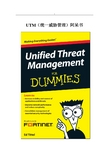
UTM(统一威胁管理)阿呆书本书是Fortinet与你分享的一本有关UTM(统一威胁管理)的深入浅出的探讨与说明。
书中我们站在网络安全设备选购者、IT技术管理者的角度谈到了网络应用以及安全的演变,防火墙以及防御技术的进化,以及如果是你来选购网络安全方案会怎样?内容简单明了。
相信每一位读此书的人都会深有感受。
每本阿呆书都有图标标识说明,这本也不例外:记着此段文字,有益于在UTM世界中继续阅读。
我们有时候会分享一些技术定义说明,如果你不感兴趣,可以跳过。
有益网络安全的关键点哦。
目录_Toc321843036第一章 (5)综合网络安全需求所在 (5)好的方面:更多更好的网络接入方式 (5)坏的方面:“混水难御” (7)丑陋的:网络犯罪与破坏 (9)第二章 (16)传统防火墙为啥挡不住如今的威胁 (16)充其量是不充分的防御 (17)单机产品会降低网络安全的可见性 (18)多台设备部署造成了对性能的打击 (21)第三章 (24)UTM:平复防御的混乱 (24)迈入UTM时代 (25)UTM:灵活,设计为未来 (26)单窗格式管理 (27)始终保持能够防御不断变化的威胁 (31)第四章 (33)UTM细节 (33)对你的网络选择对的检测技术 (33)通用处理器 VS ASIC (35)第五章 (40)统一威胁管理在生效 (40)部分成就整体 (40)端到端的彻底的防御覆盖 (44)UTM用户的现身说法 (48)第六章 (51)评估UTM解决方案的十大关键问题(Ok,准确说是十一个) (51)衡量UTM方案的几步走方法? (51)UTM方案中包含哪些安全技术? (52)UTM设备支持哪些网络功能? (53)UTM本来就支持IPv6么? (54)是否在虚拟环境下运行良好? (54)UTM解决方案是否具有可扩展性? (54)是否提供高可用性(HA)? (55)管理与报告功能怎样? (55)UTM解决方案如何领先于安全威胁? (56)购买费用如何? (57)是单次认证许可么? (57)可提供哪些支持? (58)售后培训如何? (58)厂商是否可以提供全球性服务支持? (58)在用客户的评价如何? (59)第一章综合网络安全需求所在守护不断变化的网络安全驾驭应用抵御犯罪软件在如今这个移动无所不在的世界里,网络无时不刻在变化。
联想网御UTM产品白皮书

联想网御UTM产品白皮书1. UTM产品简述1.1 什么是UTMUTM是统一威胁管理(Unified Threat Management)的缩写。
UTM设备是指由硬件、软件和网络技术组成的具有专门用途的设备,它主要提供一项或多项安全功能,将多种安全特性集成于一个硬设备中,构成一个标准的统一安全管理平台。
UTM设备应该具备的基本功能包括VPN、网络防火墙、网络入侵检测/防御和网关防病毒等功能,这几项功能并不一定要同时都得到使用,不过它们应该是UTM设备自身固有的功能。
UTM安全设备也可能包括其它特性,例如内容过滤、安全审计、安全管理、日志、服务质量(QoS)、高可用性(HA)和带宽管理等。
下图显示了UTM 系统平台上可能综合的多项安全功能。
UTM(United Threat Management)意为统一威胁管理,是指由硬件、软件和网络技术组成的具有专门用途的设备,它主要提供一项或多项安全功能,将多种安全特性集成于一个硬设备中,构成一个标准的统一安全管理平台。
1.2 UTM的优点整合所带来的成本降低将多种安全功能整合在同一产品当中能够让这些功能组成统一的整体发挥作用,相比于单个功能的累加功效更强,颇有一加一大于二的意味。
现在很多组织特别是中小企业用户受到成本限制而无法获得令人满意的安全解决方案,UTM产品有望解决这一困境。
包含多个功能的UTM安全设备价格较之单独购买这些功能为低,这使得用户可以用较低的成本获得相比以往更加全面的安全防御设施。
降低信息安全工作强度由于UTM安全产品可以一次性的获得以往多种产品的功能,并且只要插接在网络上就可以完成基本的安全防御功能,所以无论在部署过程中可以大大降低强度。
另外,UTM安全产品的各个功能模块遵循同样的管理接口,并具有内建的联动能力,所以在使用上也远较传统的安全产品简单。
同等安全需求条件下,UTM安全设备的数量要低于传统安全设备,无论是厂商还是网络管理员都可以减少服务和维护工作量。
UTM设备安装指南说明书

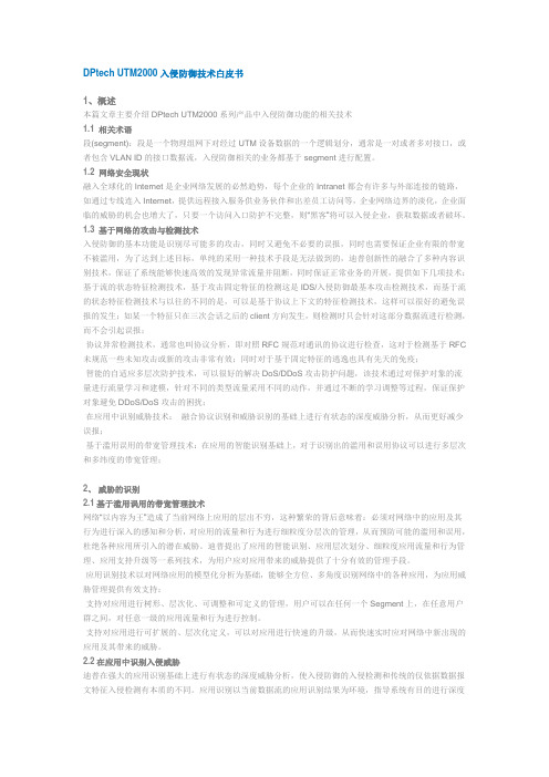
Installation GuideFamiliarize yourself with the connectors and controls on the back of the unit.Complete the Basic SetupFollow these steps to quickly setup the UTM appliance.Connect the UnitFor initial setup, connect the WAN Ethernet port to an active WAN connection such as a broadband modern, connect a DHCP enabled PC to a LAN port, and turn on the unit.Verify the following:• Power LED : It takes about a minute to boot. The power LED should turn solidgreen. If it does not, see the Troubleshooting section of the Reference Manual . • Test LED : When you first turn on the unit, the amber test LED will be lit forapproximately 2 minutes.• WAN Status LED : The status LED on the connected WAN port should be lit. Ifnot, make sure the Ethernet cable is securely attached to the modem and the WAN port, and that the modem is powered on.• LAN Status LED : A LAN status LED should be lit. If not, ensure that the Ethernetcable from the computer to the unit is securely attached at both ends, and that the computer is turned on.Log in to the Unit1. Use a browser to connect tohttps://192.168.1.1.7. Kensington lock 8. Console port 9. Factory reset button10. Power connector7109https://192.168.1.12. When prompted, enter admin for the UserName and password for the Password. Click Login.You are now connected. After 5 minutes of inactivity (the default login time-out), you are automatically logged out.Note: When the unit scans secure HTTPS traffic, import its root CA certificate into client browsers. Click the link at the bottom of the login screen to download it.Use the Setup Wizard for Basic ConfigurationThe Setup Wizard will guide you through the basic network and scanning setup. Note: If you choose to bypass the Setup Wizard, be sure to configure an alerts email address and change the admin password.1. Start the Setup Wizard.Select Wizards > SetupWizard to start the wizard.For guidance on how to fill in the wizard screens, refer to the online help or the Reference Manual via a link in theSupport > Documentation page.2. Use the Setup Wizard to configure these basic network and scanning settings:• LAN and WAN network settings.• System time (NTP server) and time zone.• Scanning of network protocols and services.• Default scan actions when the unit detects threats.• Scan exceptions like the maximum file size.• Specify the notification server and notices to be used in email notifications.•Scan engine and signature updates.ProSecure™ Unified Threat Management (UTM) ApplianceFollow these instructions to configure your ProSecure Unified Threat Management appliance to use a single WAN interface, and enable the default threat management scanning. Then, consult the Reference Manual for instructions on configuring other options such as multiple WAN settings, VPN, firewall, and custom scanning. You can access the Reference Manual from the product management interface, via the Resource CD and from the NETGEAR support site: . Estimated time: 30 minutes.Verify the Package Contents• ProSecure™ UTM appliance. • Installation Guide.• Resource CD.• Rubber feet (4) with adhesive backing.• Rack mount brackets (some models).• Power cord.Familiarize Yourself with the UnitFamiliarize yourself with the ports and status lights on the front of the unit.1.Green power LED2.Amber test LEDB port (for future use)4.Gigabit LAN portsN port 4 DMZ identifier6.Gigabit WAN ports, dualWAN model shown12536November 2010This symbol was placed in accordance with the European Union Directive 2002/96 on the Waste Electrical and Electronic Equipment (the WEEE Directive). If disposed of within the European Union, this product should be treated and recycled in accordance with the laws of your jurisdiction implementing the WEEE Directive.©2010 by NETGEAR, Inc. All rights reserved. NETGEAR and the NETGEAR logo are registered trademarks of NETGEAR, Inc. in the United States and/or other countries. Other brand and product names are trademarks or registered trademarks of their respective holders. Information is subject to change without notice.3. Click Apply to save your changes.The unit will reboot. Your computer will lose its connection to the unit if its IP address is now on a different subnet. If so, restart the computer to refresh its network settings.LicensesYour unit is bundled with three 30-day trial licenses.• Web scanning • Email scanning• Support and maintenanceActivating the licenses starts their term of use. Activate the licenses only when you are ready to start using this unit. If your unit has never been registered before you can use the 30 day trial period for all 3 types of licenses to perform initial testing and configuration.Note: Be sure the unit has Internet access before registering the licenses.• Activate the trial licenses by selecting Support > Registration and click the “Trial ” button. Once you activate the trial licenses, you can then update the unit with the latest UTM build and signature & engines during the 30-day trialperiod.• If you purchase a license subscription bundled with your unit, a license will be assigned to your unit’s serial number. When you register your unit, the license key will automatically be downloaded to your unit. Select Support > Registration , fill out the registration page, and click “Register ” to activate the services. Note: the 30-day trial licenses will be revoked once you activate the purchased service license keys. The purchased service license keys offer one year or three years of service.For additional information on licenses see the reference manual.Register and Activate the LicensesNote: Be sure the unit has Internet access before registering the licenses.1. Log in to the unit.2. Select Support > Registrationto display the Registration tab.3. Enter the customer information. If using the trial licenses, click Trial . If youhave purchased licenses, click Register . The unit will activate the licenses. After registration is complete the unit will display the license keys and their expiration dates.Online Documentation and SupportSelect Support > Documentation to view the reference manual. Select Support > Knowledge Base to view the support page, which includes this document and the reference manual. Going to/support and selecting your product modelnumber takes you to the same page.Consult the reference manual for instructions on how to use the online supportremote diagnostics.Technical SupportThank you for selecting NETGEAR products.After installing your device, locate the serial number on the label of your product and use it to register your product at /register . Registration is required before you can use the telephone support service. Registration via our website is strongly recommended.Go to for product updates and Web support . For additional information about setting up, configuring, and using your Product Name Only, see the User Manual .For complete DoC please visit the NETGEAR EU Declarations of Conformity website at: /app/answers/detail/a_id/11621/。
DPtech UTM2000 统一威胁管理
DPtech UTM2000入侵防御技术白皮书1、概述本篇文章主要介绍DPtech UTM2000系列产品中入侵防御功能的相关技术1.1 相关术语段(segment):段是一个物理组网下对经过UTM设备数据的一个逻辑划分,通常是一对或者多对接口,或者包含VLAN ID的接口数据流,入侵防御相关的业务都基于segment进行配置。
1.2 网络安全现状融入全球化的Internet是企业网络发展的必然趋势,每个企业的Intranet都会有许多与外部连接的链路,如通过专线连入Internet,提供远程接入服务供业务伙伴和出差员工访问等,企业网络边界的淡化,企业面临的威胁的机会也增大了,只要一个访问入口防护不完整,则“黑客”将可以入侵企业,获取数据或者破坏。
1.3 基于网络的攻击与检测技术入侵防御的基本功能是识别尽可能多的攻击,同时又避免不必要的误报,同时也需要保证企业有限的带宽不被滥用,为了达到上述目标,单纯的采用一种技术手段是无法做到的,迪普创新性的融合了多种内容识别技术,保证了系统能够快速高效的发现异常流量并阻断,同时保证正常业务的开展,提供如下几项技术:基于流的状态特征检测技术,基于攻击固定特征的检测这是IDS/入侵防御最基本攻击检测技术,而基于流的状态特征检测技术与以往的不同的是,可以是基于协议上下文的特征检测技术,这样可以很好的避免误报的发生;如某一个特征只在三次会话之后的client方向发生,则检测时只会针对这部分数据流进行检测,而不会引起误报;·协议异常检测技术,通常也叫协议分析,即对照RFC规范对通讯的协议进行检查,这对于检测基于RFC 未规范一些未知攻击或新的攻击非常有效;同时对于基于固定特征的逃逸也具有先天的免疫;·智能的自适应多层次防护技术,可以很好的解决DoS/DDoS攻击防护问题,该技术通过对保护对象的流量进行流量学习和建模,针对不同的类型流量采用不同的动作,并通过不断的学习调整等过程,保证保护对象避免DDoS/DoS攻击的困扰;·在应用中识别威胁技术:融合协议识别和威胁识别的基础上进行有状态的深度威胁分析,从而更好减少误报;·基于滥用误用的带宽管理技术:在应用的智能识别基础上,对于识别出的滥用和误用协议可以进行多层次和多纬度的带宽管理;2、威胁的识别2.1基于滥用误用的带宽管理技术网络“以内容为王”造成了当前网络上应用的层出不穷,这种繁荣的背后意味着:必须对网络中的应用及其行为进行深入的感知和分析,对应用的流量和行为进行细粒度分层次的管理,从而预防可能的滥用和误用,杜绝各种应用所引入的潜在威胁。
- 1、下载文档前请自行甄别文档内容的完整性,平台不提供额外的编辑、内容补充、找答案等附加服务。
- 2、"仅部分预览"的文档,不可在线预览部分如存在完整性等问题,可反馈申请退款(可完整预览的文档不适用该条件!)。
- 3、如文档侵犯您的权益,请联系客服反馈,我们会尽快为您处理(人工客服工作时间:9:00-18:30)。
DPtech UTM2000系列统一威胁管理安装手册杭州迪普科技有限公司为客户提供全方位的技术支持。
通过杭州迪普科技有限公司代理商购买产品的用户,请直接与销售代理商联系;直接向杭州迪普科技有限公司购买产品的用户,可直接与公司联系。
杭州迪普科技有限公司地址:杭州市滨江区通和路68号中财大厦6层邮编:310052声明Copyright2009杭州迪普科技有限公司版权所有,保留一切权利。
非经本公司书面许可,任何单位和个人不得擅自摘抄、复制本书内容的部分或全部,并不得以任何形式传播。
由于产品版本升级或其他原因,本手册内容有可能变更。
杭州迪普科技有限公司保留在没有任何通知或者提示的情况下对本手册的内容进行修改的权利。
本手册仅作为使用指导,杭州迪普科技有限公司尽全力在本手册中提供准确的信息,但是杭州迪普科技有限公司并不确保手册内容完全没有错误,本手册中的所有陈述、信息和建议也不构成任何明示或暗示的担保。
目录第1章产品介绍1-11.1产品概述1-1 1.2产品型号及规格介绍1-1 1.3前后面板介绍1-3 1.3.1UTM2000-MA-N/UTM2000-ME-N/UTM2000-MS-N/UTM2000-CS-N产品外观1-3 1.3.2UTM2000-GS-N/UTM2000-GM-N产品外观1-5 1.3.3UTM2000-CA-N产品外观1-7 1.3.4UTM2000-GA-N产品外观1-9 1.3.5UTM2000-GE-N/UTM2000-TS-N产品外观1-11 1.4端口介绍1-14 1.4.1C ONSOLE口1-14 1.4.210/100/1000B ASE-T以太网电接口1-14 1.4.3SFP口1-16 1.5产品组件1-18 1.5.1处理器及存储器1-18 1.5.2各类接口1-18第2章安装前的准备2-222.1通用安全注意事项2-22 2.2检查安装场所2-22 2.2.1温度/湿度要求2-22 2.2.2洁净度要求2-23 2.2.3防静电要求2-23 2.2.4抗干扰要求2-24 2.2.5防雷击要求2-24 2.2.6接地要求2-24 2.2.7布线要求2-24 2.3安装工具2-25第3章设备安装3-13.1安装前的确认3.2安装流程3-2 3.3安装设备到指定位置3-2 3.3.2安装设备到工作台3-3 3.3.3安装设备到19英寸机柜3-4 3.4连接接地线3-5 3.5连接接口线缆3-6 3.5.1连接配置口线缆3-6 3.5.2连接网络管理口3-7 3.5.3连接业务口3-7 3.6连接电源线3-7 3.7安装后检查3-7第4章设备启动及软件升级4-14.1设备启动4-1 4.1.1搭建配置环境4-1 4.1.2设备上电4-4 4.1.3启动过程4-5 4.2W EB默认登录方式4-6第5章常见问题处理5-15.1电源系统问题故障处理5-1 5.2设备故障处理5-1图形目录图1-1UTM2000-MA-N/UTM2000-ME-N/UTM2000-MS-N/UTM2000-CS-N前视图1-3图1-2UTM2000-MA-N/UTM2000-ME-N/UTM2000-MS-N/UTM2000-CS-N前面板指示灯1-4图1-3UTM2000-MA-N/UTM2000-ME-N/UTM2000-MS-N/UTM2000-CS-N后视图1-5图1-4UTM2000-GS-N/UTM2000-GM-N前视图1-5图1-5UTM2000-GS-N/UTM2000-GM-N前面板指示灯1-6图1-6UTM2000-GS-N/UTM2000-GM-N后视图1-7图1-7UTM2000-CA-N前视图1-7图1-8UTM2000-CA-N前面板指示灯1-8图1-9UTM2000-CA-N后视图1-8图1-10UTM2000-GA-N前视图1-9图1-11UTM2000-GA-N前面板指示灯1-11图1-12UTM2000-GA-N后视图1-11图1-13UTM2000-GE-N/UTM2000-TS-N前视图1-12图1-14UTM2000-GE-N/UTM2000-TS-N前面板指示灯1-13图1-15UTM2000-GE-N/UTM2000-TS-N后视图1-14图1-16RJ45水晶头外观1-15图1-17以太网电缆的示意图1-15图1-18LC型连接器外观1-17图1-19SC型连接器外观1-17图1-20光模块示意图1-18图1-21UTM2000-MA-N/UTM2000-ME-N/UTM2000-MS-N/UTM2000-CS-N以太网接口1-19图1-22UTM2000-GS-N/UTM2000-GM-N以太网接口1-19图1-23UTM2000-CA-N以太网接口1-20图1-24UTM2000-GA-N以太网接口1-20图1-25UTM2000-GE-N/UTM2000-TS-N以太网接口1-21图3-1设备安装流程3-2图3-2安装设备于工作台3-4图3-3安装挂耳3-4图3-4安装设备到机柜(为清晰起见省略了机柜)3-4图3-5固定设备3-5图3-6连接接地线示意图3-5图3-7连接保护地线到接地排3-6图4-1通过Console口进行本地配置示意图图4-2超级终端连接描述界面图4-3超级终端连接使用串口设置4-2图4-4串口参数设置4-3图4-5超级终端窗口4-3图4-6终端类型设置4-4图4-7Web网管登录页面4-7表格目录表1-1Console口属性表1-14表1-2千兆以太网电接口属性表:1-14表1-3千兆以太网光接口属性1-16表2-1机房温度/湿度要求2-22表2-2机房灰尘含量要求2-23表2-3机房有害气体限值2-23表4-1设置串接口属性4-2第1章产品介绍1.1产品概述DPtech UTM2000系列统一威胁管理创新性地采用了“多业务并行处理引擎(MPE)”技术,在多功能开启情况下性能不受影响,能够满足防护混合威胁的安全需求。
可以提供防火墙、VPN、漏洞防护、防病毒、防垃圾邮件、URL过滤和行为审计等功能,是综合安全业务保障的最佳选择。
UTM2000具有高密度接口满足多ISP的冗余需求,高扩展性可以降低后续投入成本。
适用于中小型网络出口和数据中心。
1.2产品型号及规格介绍DPtech UTM2000统一威胁管理目前包含机型如下:l UTM2000-MA-N UTM2000-ME-N UTM2000-MS-N UTM2000-CS-Nl UTM2000-GS-N UTM2000-GM-Nl UTM2000-CA-Nl UTM2000-GA-Nl UTM2000-GE-N UTM2000-TS-N各款机型的规格如下:1.3前后面板介绍1.3.1UTM2000-MA-N/UTM2000-ME-N/UTM2000-MS-N/UTM2000-CS-N 产品外观1.前视图(1)10/100/1000M 以太网电接口(2)CONSOLE 配置口(3)系统运行指示灯(RUN)(4)电源指示灯(POWER)(5)插槽指示灯(0)(6)插槽指示灯(1)(7)10/100/1000M 以太网电接口指示灯(8)USB 接口图1-1UTM2000-MA-N/UTM2000-ME-N/UTM2000-MS-N/UTM2000-CS-N 前视图图1-2UTM2000-MA-N/UTM2000-ME-N/UTM2000-MS-N/UTM2000-CS-N前面板指示灯2.后视图(1)接地标识(2)接地端子(3)交流电源插座图1-3UTM2000-MA-N/UTM2000-ME-N/UTM2000-MS-N/UTM2000-CS-N后视图1.3.2UTM2000-GS-N/UTM2000-GM-N产品外观1.前视图(1)1000M以太网光接口(2)10/100/1000M以太网电接口(3)CONSOLE配置口(4)系统运行指示灯(RUN)(5)电源指示灯(PWR0)(6)电源指示灯(PWR1)(7)插槽指示灯(SLOT)(8)1000M以太网光接口指示灯(9)10/100/1000M以太网电接口指示灯(10)USB接口图1-4UTM2000-GS-N/UTM2000-GM-N前视图图1-5UTM2000-GS-N/UTM2000-GM-N 前面板指示灯2.后视图(1)交流电源插座(2)接地端子图1-6UTM2000-GS-N/UTM2000-GM-N 后视图1.3.3UTM2000-CA-N 产品外观1.前视图(1)10/100/1000M 以太网电接口(0)(2)1000M 以太网光接口(7)(3)1000M 以太网光接口指示灯(8)(4)1000M 以太网光接口指示灯(7)(5)1000M 以太网光接口(8)(6)电源指示灯(PWR)(7)系统运行指示灯(RUN)(8)10/100/1000M 以太网电接口指示灯(0)图1-7UTM2000-CA-N 前视图图1-8UTM2000-CA-N前面板指示灯2.后视图(2)RST按键1~5S复位系统(1)USB接口按键5S以上恢复出厂设置(3)电源插座(4)接地标识(5)接地端子图1-9UTM2000-CA-N后视图1.3.4UTM2000-GA-N产品外观1.前视图(1)10/100/1000M以太网电接口(2)1000M以太网光接口(3)LCD显示屏(4)CONSOLE配置口(5)USB口(6)10/100/1000M以太网电接口(0/0)(7)10/100/1000M以太网电接口(0/1)(8)10/100/1000M以太网电接口指示灯(9)1000M以太网光接口指示灯(10)系统运行指示灯(RUN)(11)系统告警指示灯(ALM)(12)电源指示灯(PWR)(13)10/100/1000M以太网电接口指示灯(0/0)(14)10/100/1000M以太网电接口指示灯(0/1)图1-10UTM2000-GA-N前视图图1-11UTM2000-GA-N前面板指示灯2.后视图(1)交流电源插座(2)接地端子图1-12UTM2000-GA-N 后视图1.3.5UTM2000-GE-N/UTM2000-TS-N 产品外观1.前视图(1)10/100/1000M 以太网电接口(2)1000M 以太网光接口(3)LCD 显示屏(4)CONSOLE 配置口(5)10/100/1000M 以太网电接口(6)10/100/1000M 以太网电接口指示灯(7)1000M 以太网光接口指示灯(8)10000M 以太网光接口(9)10000M 以太网光接口指示灯(10)系统运行指示灯(RUN)(11)系统告警指示灯(ALM)(12)电源指示灯(PWR0)(13)电源指示灯(PWR1)(14)USB 接口(15)10/100/1000M 以太网电接口指示灯图1-13UTM2000-GE-N/UTM2000-TS-N 前视图图1-14UTM2000-GE-N/UTM2000-TS-N前面板指示灯2.后视图(1)交流电源插座(1)(2)交流电源插座(2)(3)接地端子图1-15UTM2000-GE-N/UTM2000-TS-N后视图1.4端口介绍1.4.1Console口UTM2000系列前面板均有一个RS232异步串行配置口(CON),可用来连接终端计算机,以进行系统的调试、配置、维护、管理和主机软件程序加载等工作。