AS250电脑控系统参数设置及操作培训.pptx
AS 系列快速入门手册说明书

AS系列快速入门手冊绵密网络 专业服务中达电通已建立了70余个分支机构及服务网点,并塑建训练有素的专业团队,提供客户最满意的服务,公司技术人员能在2小时内回应您的问题,并在48小时内提供所需服务。
中达电通公司版权所有如有改动,恕不另行通知400 - 820 - 9595扫一扫,关注官方微信沈阳电话:(024)2334-1160哈尔滨电话:(0451)5366-5568长春电话:(0431)8892-5060呼和浩特电话:(0471)6297-808北京电话:(010)8225-3225天津电话:(022)2301-5082济南电话:(0531)8690-6277太原电话:(0351)4039-485郑州电话:(0371)6384-2772石家庄电话:(0311)8666-7337上海电话:(021)6301-2827南京电话:(025)8334-6585杭州电话:(0571)8882-0610合肥电话 :(0551)6281-6777武汉电话:(027)8544-8475南昌电话:(0791)8625-5010成都电话:(028)8434-2075长沙电话:(0731)8549-9156重庆电话:(023)8806-0306 昆明电话:(0871)6313-7362广州电话:(020)3879-2175厦门电话:(0592)5313-601南宁电话:(0771)2621-501乌鲁木齐电话:(0991)4678-141兰州电话:(0931)6406-725西安电话:(029)8836-0780贵阳电话:(0851)8690-1374福州电话:(0591)8755-1305地址:上海市浦东新区民夏路238号邮编:201209电话:( 021 )5863-5678传真:( 021 )5863-0003网址: AS-0249310-032022/06/13AS系列快速入门手册版本修订一览表版本变更内容发行日期第一版第一版发行2016/07/15第二版1.第2.2.1节增加挡板安装说明2.第2.3.1节更新电源模块配线说明3.第2.8节更新”新增功能块”软件画面4.第2.9节更新”新增程序”软件画面5.第3.3.1节更新”新增装置监控表”软件画面2017/01/20第三版1.由于AS系列硬件手册及AS系列操作手册已合并为AS系列硬件及操作手册,故更新其相关信息2.增加DIADes igner软件相关信息及第3章DIADes igner程序规划撰写与下载监视3.第1.2节更新AS系统架构最大限制信息4.原第2章及第3章合并为第2章5.第2.1.3.1节更电源端配线信息6.第2.1.5节更新ISPSoft软件开启路径7.第2.2.1.1节更新CO MMG R软件开启路径2022/06/13AS系列快速入门手册目录第1章简介1.1 手册内容简介......................................................................... 1-2 1.2 系统架构简介......................................................................... 1-3 1.3 主机运作介绍......................................................................... 1-4第2章ISPSoft程序规划撰写与下载监视2.1 程序规划编写......................................................................... 2-32.1.1 准备工作........................................................................ 2-32.1.1.1 硬件......................................................................... 2-32.1.1.2 软件......................................................................... 2-42.1.1.3 工具与材料 ................................................................ 2-42.1.2 安装.............................................................................. 2-52.1.2.1 安装模块................................................................... 2-52.1.2.2 安装脱落式端子........................................................... 2-72.1.3 配线.............................................................................. 2-82.1.3.1 电源模块配线.............................................................. 2-82.1.3.2 数字输入模块配线........................................................ 2-92.1.3.3 数字输出模块配线........................................................ 2-92.1.3.4 模拟输入与输出模块配线.............................................. 2-102.1.3.5 送电....................................................................... 2-112.1.4 范例说明...................................................................... 2-112.1.5 建立项目...................................................................... 2-122.1.6 规划硬件架构 ................................................................ 2-152.1.7 建立全局符号 ................................................................ 2-202.1.8 建立功能块 ................................................................... 2-222.1.9 建立主要程序 ................................................................ 2-29 2.2 程序下载与监视.................................................................... 2-352.2.1 COMMGR设定.............................................................. 2-382.2.1.1 启动COMMGR ......................................................... 2-38i2.2.1.2 开启COMMGR ......................................................... 2-382.2.1.3 设定COMMGR ......................................................... 2-382.2.2 专案下载...................................................................... 2-402.2.2.1 设定项目通讯........................................................... 2-402.2.2.2 下载硬件配置........................................................... 2-412.2.2.3 下载程序内容........................................................... 2-422.2.3 程序监视与除错 ............................................................. 2-442.2.3.1 程序监视................................................................. 2-442.2.3.2 程序与系统除错 ........................................................ 2-48第3章DIADesigner程序规划撰写与下载监视3.1 程序规划编写 ........................................................................ 3-33.1.1 准备工作........................................................................ 3-33.1.1.1 硬件 ........................................................................ 3-33.1.1.2 软件 ........................................................................ 3-43.1.1.3 工具与材料................................................................ 3-43.1.2 安装............................................................................. 3-53.1.2.1 安装模块................................................................... 3-53.1.2.2 安装脱落式端子 .......................................................... 3-73.1.3 配线............................................................................. 3-83.1.3.1 电源模块配线............................................................. 3-83.1.3.2 数字输入模块配线........................................................ 3-93.1.3.3 数字输出模块配线........................................................ 3-93.1.3.4 模拟输入与输出模块配线 ............................................. 3-103.1.3.5 送电 ...................................................................... 3-113.1.4 范例说明...................................................................... 3-113.1.5 建立项目...................................................................... 3-133.1.6 规划硬件架构................................................................ 3-153.1.7 建立全局变量................................................................ 3-193.1.8 建立功能块................................................................... 3-213.1.9 建立主要程序................................................................ 3-293.2 程序下载与监视.................................................................... 3-343.2.1 COMMGR设定.............................................................. 3-34 ii3.2.1.1 启动COMMGR ......................................................... 3-34 3.2.1.2 开启COMMGR ......................................................... 3-34 3.2.1.3 设定COMMGR ......................................................... 3-35 3.2.2 专案下载...................................................................... 3-36 3.2.2.1 设定项目通讯............................................................ 3-36 3.2.2.2 下载项目-硬件配置与程序 ............................................ 3-37 3.2.3 程序监视与除错.............................................................. 3-38 3.2.3.1 程序监视................................................................. 3-38 3.2.3.2 程序与系统除错......................................................... 3-43 3.2.4 既有ISPSoft项目转移..................................................... 3-44iiiMEMO iv1第1章简介目录1.1 手册内容简介 .................................................................................. 1-2 1.2 系统架构简介 .................................................................................. 1-3 1.3 主机运行介绍 .................................................................................. 1-41-1AS系列快速入门手册1.1手册内容简介针对AS系列PLC的产品,台达依照不同的应用需求,分别为用户准备了不同的说明手册。
COMET 250 系统使用说明
COMET 250 系统使用简要说明本说明包括四大部分:系统概要、系统使用、系统标定和系统维护。
第一部分系统概要一、系统的构成1、COMET 250系统:主要包括测量头、三脚架、底座、控制器、图像处理板等硬件部分和软件COMET 250驱动程序、标定板标准参数盘、测量头参数盘等构成。
该系统主要用于覆盖件的测量和后续处理。
2、Aicon 3D Studio系统:主要包括数码相机和Aicon 3D Studio软件、相机标准参数盘等构成。
主要用于测量表面的空间定位。
二、系统的安装1、硬件安装①三脚架和底座的安装;②测量头的安装;③控制器的安装;④图像处理板的安装;应插在PCI插槽内。
⑤联线:测量头与控制器有五根连线,按颜色对应插接即可;控制器与图像处理板有两根连线,分别为时钟线和图像数据传输线;控制器与计算机主机有一根连线—数据线,应插在计算机上方的一个COM口。
2、软件安装⑴COMET 250 系统软件安装:a) 安装frame graber:选择eltec pceye-4b) 安装COMET plus:选择“英语”安装即可。
c) 系统配置(config):语言—English;内存;CPU;图像处理板等。
d) 安装参数盘:Sensor—测量头参数;Calbration—标定板参数。
⑵Aicon 3D Studio 安装a) Aicon 3D Studio安装;b) 安装参数盘:copy a:/Analyzer-Template-Data到Aicon 3D Studio目录下即可。
三、系统的启动1、启动Aicon 3D Studio用于处理数码相片(*.tif),生成*.apf文件,再经转存生成*.lst文件,以供后续测量使用。
2、启动COMET 250(Sensor)a)启动计算机;b)打开控制器电源;c)启动COMET 250。
正确启动完成后有响声。
主要用于测量。
启动后,建立测量文件*.cdb,供后续测量、处理使用。
123VISTA120、250简易操作手册

VISTAR—120简易编程操作手册一、设置6160编程键盘开机后,键盘液晶屏幕无任何显示,此时同时按1 、3键5秒,键盘显示Con Addr=31或Addr=xx,输入00按*键盘绿灯亮,显示***DISARMED***READT TO ARM键盘地址不为00时,不能编程,6148键盘不能编程二、设置每个防区在撤防状态下,才能进入编程模式输入4140 8000(4140为出厂设置的安装员密码)进入编程模式,键盘显示:Program Mode*Fill # View按*93 键盘显示ZONE PROG?1=TES 0=NO输入0 1 0,进入防区编程模式,键盘显示:ZN ZT P RC IN L001 09 1 10 HW1 此处,ZN代表防区号;ZT代表防区类型01—出入口防区1型,布防时有延时,进入时有延时,延时时间由*09和*10设定;02—出入口防区2型,布防时有延时,进入时有延时,延时时间由*11和*12设定;03—周边防区,布防时有效,撤防时无效;06—24小时无声防区;07—24小时有声防区;09—火警防区;00—无用防区。
P代表子系统;RC代表报告码,系统默认即可,无需改动;IN代表防区输入类型,1-9防区统一为01,显示为HW;10防区以后统一为06,显示为SL;L 为回路号,除了是4193SN的第二回路为2,其他都为1。
例如:编程将24防区为24小时防区则在ZN下输入024 *(下一步)在ZT下输入24防区的防区类型07(24小时放区)在P 下输入24防区所属的子系统(部分区都为1)在IN下输入06**此时,键盘显示:024 INPUT S/N :LAxxx-xxxx :1此时输入24防区地址码输入完成后按*确认,在L处选择相应的回路再按*即进入下一方的。
退出防区编程:在防区号(ZN)处输入000 *1*99 即可退出编程注意:在防区编程状态下,*代表下一步,#代表返回。
三、设置打印机(IP-2000输出)41408000*94*70 11111*71 1*72 1*73 0*99*99四、修改安装员密码安装员密码是最高级的密码,出厂设置为4140,现以0414为例41408000*00 0414*99五、系统日常操作1、外出布防绿灯(READY)亮表示所有防区未被触发,可以外出布防,输入甲级用户密码 2红灯(ARMEO)亮,表示系统外出布防2、撤防系统在布防期间没有报警,输入甲级用户密码1,系统撤防,系统在布防期间发生报警,输入甲级用户密码 1 两边,3、旁路防区后布防报警系统有时不需要对所有防区布防,这时需要对不设防的防区旁路,对其他防区布防,输入甲级用户密码 6 XXX(防区号)XXX(防区号)``````甲级用户密码 2报警系统有防区未准备(NOT READY)时,可以旁路未准备的防区,对其他防区布防,输入甲级用户密码 6 #甲级用户密码 2撤防后原来的旁路无效。
复盛空压机学习资料之一

2.
3.
4.
5.
轻故障(空滤、油分、油滤堵塞)报警不停机,重故障(排气高温或电气故障)报警 停机,必须做到故障排除后,空压机才能再启动。清除故障使用“紧停/复位”按钮。同 时有两个以上故障,状态显示优先级高的,清除后,显示优先级其次的,直至所有故 障全部清完。(重故障优先于轻故障)。 1、相序故障指示 空压机接通电源,若R、S、T相序错误,面板上相序故障灯亮,并会在液晶显示屏上显 示相序错误。禁止空压机启动;改接电源相序。 2、主电机过载指示灯 空压机在运行过程中,发生主电机过载,主电机过载灯亮,空压机停机。 3、风扇电机过载指示灯 空压机在运行过程中,发生风扇电机过载,风扇电机过载灯亮,空压机停机。 4、排气温度指示灯 空压机在运行过程中,排气温度超过报警温度时,排气温度指示灯闪烁,排气温度超过 保护温度时,指示灯常亮,空压机停机。 5、传感器报警指示灯 温度和压力传感器短路、断路或故障时,传感谢器报警灯常用亮。 6、备用指示灯 空压机运行中,当压力大于上限设定值+0.05Mpa(此值可设定)持续10s,备用指示灯 亮,空压机停机。
端子排预留如下信号: A、重故障信号扩展输出接点(当出现重故障报警:主机过载、风机过载 、相序异常、排气压力过高或排气高温等时,此触点接通,作为重故 障报警信号输出)。 B、轻故障信号扩展输出接点(空气滤清器、油气分离器、油过滤器阻塞 报警信号综合控输出)。 C、“近控/远控”方式输出接点(液晶屏参数设置中选择为近控,触点断 开;液晶屏参数设置中选择为远控,触点接通)。 D、电源指示输出点(空压机运行后,触点接通)。 E、运行信号扩展输出接点(空 压机运行后,触点接通)。 F、远程启动、远程停止控制接点(液晶屏参数设置中选择远控时,通过 这二个接点可远程启动或停止空压机)。 控制系统预留有RS485通讯接口,支持MODBUS协议的子集。
新时达AS380二代一体化驱动控制器培训(2)

英
伦
经
典
百
年
荣
耀
轿箱扩展板SM.09IO/B板
英
伦
经
典
百
年
荣
耀
轿箱扩展板SM.09IO/B板
轿箱扩展板SM.09IO/B端子定义: JP1 连接轿箱板SM.02/G JP2 连接第二块轿箱扩展板 JP6.1 输出GY0,开门保持灯输出 JP6.2 输出GY1,备用 JP6.3 输出GY2,备用 JP6.4 输出JP6.1-JP6.3公共端 JP7.1 输出GY3,备用 JP7.2 输出JP7.1公共端 JP8.1 输出GY4,备用 JP8.2 输出JP8.1公共端 JP9.1 输出GY5,备用 JP9.2 输出JP9.1公共端
英
伦
经
典
百
年
荣
耀
PG卡的类型
英
伦
经
典
百
年
荣
耀
端子定义
JP1.1 XCOM JP1.2 X20 JP1.3 X21 JP1.4 X22 JP1.5 XCOM X20-X22输入信号公共端0V 安全回路检测正电压端110V/220V输入 门锁回路检测正电压端110V/220V输入 厅门锁回路检测正电压端110V/220V输入 内部和JP1.1连
20pg卡的类型21端子定义jp11xcomx20x22输入信号公共端0vjp12x20安全回路检测正电压端110v220v输入jp13x21门锁回路检测正电压端110v220v输入jp14x22厅门锁回路检测正电压端110v220v输入jp15xcom内部和jp11连jp21y0抱闸接触器输出jp22y1抱闸强激接触器输出jp23y2主接触器输出jp24com1输出y0y2的公共端jp31y3提前开门继电器jp32y4停电应急平层完成信号输出jp33com2输出y3y4的公共端22端子定义jp34y5消防信号输出jp35com3输出继电器y5公共点jp36y6备用jp37com4输出继电器y6公共点23端子定义jp410v0vdcjp42canhcan通讯txa0指令和外呼jp43canlcan通讯txa0指令和外呼jp510v0vdcjp52canhcan通讯txa1并联或群控jp53canlcan通讯txa1并联或群控jp610v0vdcjp62canhcan通讯txa2小区监控jp63canlcan通讯txa2小区监控24端子定义jp81x0检修信号1jp82x1检修信号2jp83x2上行信号jp84x3下行信号jp85x4上行第一终端减速开关jp86x5下行第一终端减速开关jp87x6上平层开关jp88x7下平层开关jp89x8电动机电源接触器检测jp810x9抱闸接触器检测25端子定义jp91x10左抱闸开关检测jp92x11右抱闸开关检测jp93x12电动机温度检测信号jp94x13提前开门继电器检测jp95x14门区信号检测jp96x15消防返回消防员信号参数选择jp97x16停电应急平层输入地震大楼后备电源参数选择jp98x17门锁回路继电器检测jp99x18上行第二终端减速开关jp910x19下行第二终端减速开关26端子定义jp1110v模拟量输入0vjp112ain差分模拟量输入jp113ain差分模拟量输入拨码开关sw2监控终端电阻有效sw3程序烧录状态27轿箱板sm02g板28轿箱板sm02g板sm02g板端子定义
SINAMICS G120 CU250S-2控制单元操作指南说明书
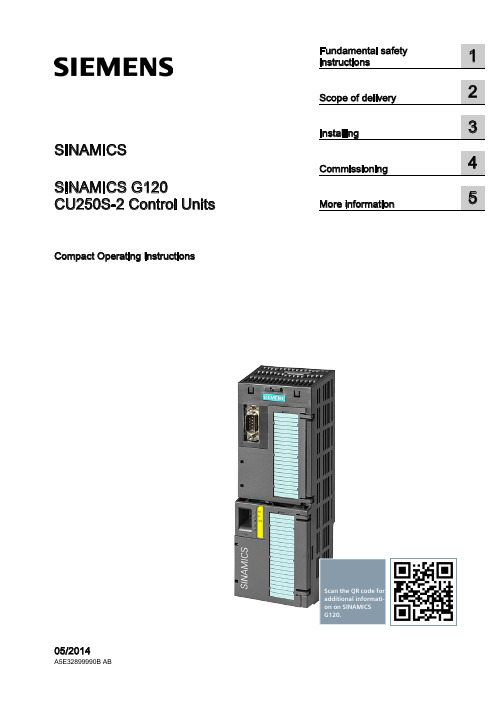
SINAMICSSINAMICS G120CU250S-2 Control UnitsCompact Operating InstructionsScan the QR code foradditional informati-on on SINAMICSG120.Siemens AG Industry Sector Postfach 48 48 A5E32899990B ABⓅ 07/2014 Subject to changeCopyright © Siemens AG 2014.All rights reservedLegal informationWarning notice systemThis manual contains notices you have to observe in order to ensure your personal safety, as well as to preventdamage to property. The notices referring to your personal safety are highlighted in the manual by a safety alertsymbol, notices referring only to property damage have no safety alert symbol. These notices shown below aregraded according to the degree of danger.DANGERindicates that death or severe personal injury will result if proper precautions are not taken.WARNINGindicates that death or severe personal injury may result if proper precautions are not taken.CAUTIONindicates that minor personal injury can result if proper precautions are not taken.NOTICEindicates that property damage can result if proper precautions are not taken.If more than one degree of danger is present, the warning notice representing the highest degree of danger willbe used. A notice warning of injury to persons with a safety alert symbol may also include a warning relating toproperty damage.Qualified PersonnelThe product/system described in this documentation may be operated only by personnel qualified for the specifictask in accordance with the relevant documentation, in particular its warning notices and safety instructions.Qualified personnel are those who, based on their training and experience, are capable of identifying risks andavoiding potential hazards when working with these products/systems.Proper use of Siemens productsNote the following:WARNINGSiemens products may only be used for the applications described in the catalog and in the relevant technicaldocumentation. If products and components from other manufacturers are used, these must be recommendedor approved by Siemens. Proper transport, storage, installation, assembly, commissioning, operation andmaintenance are required to ensure that the products operate safely and without any problems. The permissibleambient conditions must be complied with. The information in the relevant documentation must be observed. TrademarksAll names identified by ® are registered trademarks of Siemens AG. The remaining trademarks in this publicationmay be trademarks whose use by third parties for their own purposes could violate the rights of the owner. Disclaimer of LiabilityWe have reviewed the contents of this publication to ensure consistency with the hardware and softwaredescribed. Since variance cannot be precluded entirely, we cannot guarantee full consistency. However, theinformation in this publication is reviewed regularly and any necessary corrections are included in subsequenteditions.Table of contents1 Fundamental safety instructions (4)1.1 General safety instructions (4)1.2 Industrial security (5)2 Scope of delivery (6)3 Installing (7)3.1 Snapping the Control Unit onto the Power Module (7)3.2 Overview of the interfaces (8)3.3 Terminal blocks (10)3.4 Operator panels (14)4 Commissioning (15)4.1 Commissioning with STARTER (15)4.2 Connecting the inverter to the fieldbus (20)4.3 Frequently required parameters (22)5 More information (25)5.1 Manuals for your inverter (25)5.2 Product support (26)This manual describes how you install a SINAMICS G120 converter with CU250S-2 ControlUnit and commission it.What is the meaning of the symbols in the manual?An operating instruction starts here.This concludes the operating instruction.CU250S-2 Control UnitsCU250S-2 Control Units1Fundamental safety instructions1.1General safety instructionsWARNINGRisk of death if the safety instructions and remaining risks are not carefully observedIf the safety instructions and residual risks are not observed in the associated hardware documentation, accidents involving severe injuries or death can occur. • Observe the safety instructions given in the hardware documentation. • Consider the residual risks for the risk evaluation.WARNINGDanger to life or malfunctions of the machine as a result of incorrect or changed parameterizationAs a result of incorrect or changed parameterization, machines can malfunction, which in turn can lead to injuries or death.• Protect the parameterization (parameter assignments) against unauthorized access. • Respond to possible malfunctions by applying suitable measures (e.g. EMERGENCY STOP or EMERGENCY OFF).Fundamental safety instructions1.2 Industrial security 1.2Industrial securityNoteIndustrial securitySiemens provides products and solutions with industrial security functions that support thesecure operation of plants, solutions, machines, equipment and/or networks. They areimportant components in a holistic industrial security concept. With this in mind, Siemens’products and solutions undergo continuous development. Siemens recommends strongly thatyou regularly check for product updates.For the secure operation of Siemens products and solutions, it is necessary to take suitablepreventive action (e.g. cell protection concept) and integrate each component into a holistic,state-of-the-art industrial security concept. Third-party products that may be in use shouldalso be considered. For more information about industrial security, visit Hotspot-Text(/industrialsecurity).To stay informed about product updates as they occur, sign up for a product-specificnewsletter. For more information, visit Hotspot-Text ().WARNINGDanger as a result of unsafe operating states resulting from software manipulationSoftware manipulation (e.g. by viruses, Trojan horses, malware, worms) can cause unsafeoperating states to develop in your installation which can result in death, severe injuriesand/or material damage.•Keep the software up to date.You will find relevant information and newsletters at this address().•Incorporate the automation and drive components into a holistic, state-of-the-artindustrial security concept for the installation or machine.You will find further information at this address(/industrialsecurity).•Make sure that you include all installed products into the holistic industrial securityconcept.CU250S-2 Control UnitsCU250S-2 Control Units2Scope of deliveryScope of deliveryThe delivery comprises at least the following components:● A CU250S-2 Control Unit ready for operation with installed firmware.Options for upgrading and downgrading the firmware can be found on the Internet: Firmware (/WW/news/en/67364620).The fieldbus interface of the Control Unit depends on the order number. The order number, the designation and the version of the hardware (e.g. 02) and firmware (e.g. 4.6) can be found on the rating plate ① of the Control Unit. Designation Order number FieldbusCU250S-2 6SL3246-0BA22-1BA0 USS, Modbus RTU CU250S-2 DP 6SL3246-0BA22-1PA0 PROFIBUSCU250S-2 PN 6SL3246-0BA22-1FA0 PROFINET, EtherNet/IP CU250S-2 CAN6SL3246-0BA22-1CA0CANopen● Compact Operating Instructions in German and English● The inverter contains open-source software (OSS). The OSS license terms are saved in the inverter.Transferring license terms of the OSS code to a PCProcedureTo transfer the OSS license terms from the inverter to a PC, proceed as follows: 1. Switch off the inverter power supply.2. Insert an empty memory card into the card slot of the inverter. Also see Section:Overview of the interfaces (Page 8)3. Switch on the inverter power supply.4. When you have switched on the power supply, wait 30 seconds.During this time, the inverter writes the "Read_OSS.ZIP" file onto the memory card. 5. Switch off the inverter power supply. 6. Remove the card from the inverter. 7. Use a card reader and load the file to a PC.You have then transferred the OSS license terms from the inverter to a PC.CU250S-2 Control UnitsInstalling33.1Snapping the Control Unit onto the Power ModuleInstalling the Control Unit on an IP20 Power ModuleProcedureProceed as follows to connect Power Modules and Control Units:1. Locate the lugs at the rear of the Control Unit in the matching recesses of the Power Module.2. Mount the Control Unit onto the Power Module so that it audibly snaps into place.The Power Module and the Control Unit are now connected with one another.To remove the Control Unit, press on the release button on the Power Module and withdraw the Control Unit.Permissible Power ModulesYou may operate the Control Unit with the following Power Modules: ● PM240 ● PM240-2 ● PM250 ● PM260 ● PM340 1AC3.2 Overview of the interfacesCU250S-2 Control Units3.2 Overview of the interfacesTo access the interfaces at the front of the Control Unit, you must unplug the Operator Panel (if one is being used) and open the front doors.① Terminal strips ② Fieldbus interfaceSelecting the fieldbus address: • PROFIBUS • USS • Modbus RTU •CanOpen③Status LED④ USB interface for connection to a PC⑤ No function. Keep the switch in the "Vector"position. ⑥Switch for analog inputsI0/4 mA … 20 mAU-10/0 V … 10 V⑦ Connection to the operator panel ⑧Memory card slot3.2 Overview of the interfacesCU250S-2 Control UnitsInterfaces at the lower side of the Control UnitTable 3- 1 Permissible encoders on the DRIVE-CLiQ interface X100The permissible combinations of encoders for speed control and position control are listed in the "Basic Positioner" Function Manual, see also: Manuals for the Control Unit (/WW/view/en/30563628/133300).3.3 Terminal blocksCU250S-2 Control Units3.3 Terminal blocksTerminal strips behind the upper front doorDifferent reference potentials:The terminals labelled "GND" are connected internally. "GND" and "GND IN" are not connected internally.Figure 3-1Interconnection example of the digital inputs with external 24 V power supplyInterconnecting the analog inputs (terminals 3, 4 and 10, 11)For the analog inputs, you may use the internal 10 V supply (example: terminals 1 … 4, 13) or an external supply (example: terminals 10, 11).If you use the internal 10 V supply, you must connect AI 0- or AI 1- to GND.3.3 Terminal blocks Optional 24 V supply (terminals 31, 32)Connection of the optional 24 V supply has the following advantages:● The Control Unit remains in operation after disconnection of the Power Module from theline supply. The Control Unit thus maintains the fieldbus communication, for example.● You can use terminals 51 … 54 as digital outputs.Use a power supply that provides an output voltage in accordance with SELV (Safety ExtraLow Voltage) or PELV (Protective Extra Low Voltage).If you use a common external power supply for terminals 31, 32 and the digital inputs, youmust connect GND to GND IN. Terminal strips behind the lower front doorDifferent reference potentials: The reference potentials of the digital inputs are not connected internally to each other or to GND. Figure 3-2 Interconnection example of the digital inputs with external 24 V power suppliesInterconnecting the reference potential of the digital inputsTable 3- 2Supply options for the digital inputs3.3 Terminal blocksFactory setting of the terminal stripsThe factory setting of the terminals depends on the Control Unit.Control Units with USS or CANopen interfaceThe fieldbus interface is not active.Figure 3-3 Factory setting of the CU250S-2 and CU250S-2 CAN Control Units3.3 Terminal blocksControl Units with PROFIBUS or PROFINET interfaceThe function of the fieldbus interface depends on DI 3.Figure 3-4 Factory setting of the CU250S-2 DP and CU250S-2 PN Control Units3.4 Operator panelsChanging the function of the terminalsThe function of the terminals marked in color in the two figures above, can be set.In order that you do not have to successively change terminal for terminal, several terminalscan be jointly set using default settings ("p0015 Macro drive unit").The factory settings of the terminals for USS/CANopen and PROFIBUS/PROFINETdescribed above correspond to the following default settings:●p0015 = 12 (setting in STARTER: "Standard I/O with analog setpoint")●p0015 = 7 (setting in STARTER: "Fieldbus with data set switchover")Further default settings can be found in the Operating Instructions, see also: Manuals for theControl Unit (/WW/view/en/30563628/133300).Wiring the terminal strip in compliance with EMC1.If you use shielded cables, then you must connect the shield to the mounting plate of thecontrol cabinet or with the shield support of the inverter through a good electricalconnection and a large surface area.See also: EMC installation guideline(/WW/view/en/60612658)e the shield connection plate (order number 6SL3264-1EA00-0LA0) of the Control Unitas strain relief.3.4Operator panelsThe Intelligent Operator Panel (IOP) is available for snapping on to the ControlUnit or as handheld with a connection cable to the Control Unit. The graphics-capable plain text display of the IOP enables intuitive operation and diagnosticsof the inverter.See also: Compatibility of the IOP and Control Units(/WW/view/en/67273266)The BOP-2 is an operator panel for snapping on to the Control Unit. The BOP-2has a two-line display for operation and diagnostics of the inverter.Further information can be found in the Operating Instructions of the BOP-2 and the IOP: Operator Panels (/WW/view/en/30563514/133300).Commissioning4Requirements for commissioningUse one of the PC tools STARTER or Startdrive to commissionthe inverter.You can access the inverter with STARTER or Startdrive eithervia a USB connection or via the fieldbus.System requirements and download:• STARTER(/WW/view/en/26233208)• Startdrive(/WW/view/en/88851265) Help for the operation and for the functions of the commissioning tools:● STARTER videos (/mcms/mc-drives/en/low-voltage-inverter/sinamics-g120/videos/Pages/videos.aspx )● Startdrive tutorial (/WW/view/en/73598459)Commissioning with STARTER is described in the following.4.1 Commissioning with STARTERCreating a STARTER projectProcedureIn order to create a new project, proceed as follows:1. In the STARTER menu, select "Project" → "New…".2. Specify a name of your choice for the project.You have created a new STARTER project.4.1 Commissioning with STARTERTransferring inverters connected via USB to the projectProcedureProceed as follows to transfer an inverter connected via USB to your project:1.Switch on the inverter power supply.2.First insert a USB cable into your PC and then into the inverter.3.The PC operating system installs the USB driver when you are connecting the inverterand PC together for the first time.–Windows 7 installs the driver automatically.–For Windows XP you must acknowledge several system messages.4.Start the STARTER commissioning software.5.In STARTER, press the ("Accessible nodes") button.6.When the USB interface is appropriately set, then the "Accessible nodes" screen formshows the inverters that can be accessed.If you have not correctly set the USB interface, then the following "No additional nodesfound" message is displayed. In this case, follow the description below.7.Select the inverter ☑.8.Press the "Accept" button.You have transferred an inverter accessible via the USB interface into your project.4.1 Commissioning with STARTER Setting the USB interfaceProcedureProceed as follows to set the USB interface in STARTER:1.In this case set the "Access point" to "DEVICE (STARTER, Scout)" and the "PG/PCinterface" to "S7USB".2.Press the "Update" button.You have set the USB interface.STARTER now shows the inverters connected via USB.Starting the configurationProcedureTo start the configuration, proceed as follows:1.In STARTER select the drive you wish to commission.2.Start the wizard for the device configuration:You have started the configuration.4.1 Commissioning with STARTERPerforming the configurationFollow the steps of the configuration wizard and enter the data ofyour application.Loading the configured data into the driveProcedureProceed as follows to load the configured data into the drive:1. Select your project and go online: .2. STARTER compares your configuration with the real inverter. STARTER signals anydifferences in the "Online/offline comparison".Acknowledge the message by pressing the "Load HW configuration to PG" button.3. Open "Drive Navigator".4. Select the "Commissioning" button.5.Click on "Load data to the drive".6. ☑ In the screen form, select "After loading copy RAM to ROM".7. Load your configuration into the inverter.8. Close the "Commissioning" screen form.You have loaded your configuration into the drive and therefore performed the basiccommissioning.Identifying motor dataRequirements● In the basic commissioning, you have selected the motor identification (MOT ID). In thiscase, after the basic commissioning has been completed, the inverter issues the alarmA07991.● The motor has cooled down to the ambient temperature.If the motor is too hot, the motor data identification will provide incorrect values and thevector control will become unstable.4.1 Commissioning with STARTERDANGERRisk of injury or material damage as a result of machine movements when switching on themotorSwitching on the motor for identification purposes may result in hazardous machinemovements.Secure dangerous machine parts before starting motor data identification:•Before switching on, check that no parts are loose on the machine or can be spun out.•Before switching on, ensure that nobody is working on the machine or located within its working area.•Secure the machine's work area against unintended access.•Lower hanging/suspended loads to the floor.ProcedureTo initiate motor data identification and optimizationof the motor control, proceed as follows:1.Open by double-clicking on the control panel inSTARTER.2.Assume master control for the inverter.3.Set the "Enable signals"4.Switch on the motor.The inverter starts the motor data identification.This measurement can take several minutes.After the measurement, the inverter switches offthe motor.5.Relinquish the master control after the motor dataidentification.6.Click the Save (RAM to ROM) button.You have now completed motor data identification.Self-optimization of the closed-loop controlIf you have also selected a rotating measurement with self-optimization of the vector controlin addition to the motor data identification, then you must switch on the motor again asdescribed above and wait for the optimization run to be completed.4.2 Connecting the inverter to the fieldbus4.2Connecting the inverter to the fieldbusWhere can I find instructions for the fieldbus connection of the inverter?You can find instructions for the fieldbus connection on the Internet:●Application examples (/WW/view/en/60733299)●Operating Instructions, "Inverter with CU250S-2 Control Units": Manuals for the ControlUnit (/WW/view/en/30563628/133300)●Function Manual, "Fieldbusses": Manuals for the Control Unit(/WW/view/en/30563628/133300)Example telegramThe inverter telegrams without configured basic positioner are described in the OperatingInstructions and in the "Communications" Function Manual: Manuals for the Control Unit(/WW/view/en/30563628/133300)The telegrams with configured basic positioner are described in the "Basic Positioner andTechnology" Function Manual: Manuals for the Control Unit(/WW/view/en/30563628/133300).Control word 1 (STW1)4.2 Connecting the inverter to the fieldbusStatus word 1 (ZSW1)4.3 Frequently required parametersDescription files for fieldbusesThe description files are electronic device data sheets which contain all the requiredinformation of a higher-level controller. You can configure and operate the inverter on afieldbus with the appropriate description file.4.3Frequently required parameters4.3 Frequently required parameters4.3 Frequently required parametersMore information 5 5.1Manuals for your inverterDocumentation on DVDSINAMICS Manual Collection, order number 6SL3097-4CA00-0YG0Table 5- 1 Manuals for your inverter for downloadMore information5.2 Product support5.2Product support Table 5- 2 Technical support。
AS系统管理员培训
50级 - C2 Level Security
C2安全级是商业计算机中的最高安全级别
用户描述
用户类(User Class) 可操作对象(Object Owned and Authorized) 对象的权限(Authorization of Objects)
特权指令与特殊权限
(Privileged Instructions and Special Authorities)
Shared L2 Shared L2
Distributed Switch
Distributed Shared L2 Switch
Distributed Switch
Enhanced Scaling Simultaneous Multi-Threading (SMT) Enhanced Distributed Switch Enhanced Core Parallelism Improved FP Performance Increased memory bandwidth Reduced memory latencies Virtualization
AS/400的历史及其发展
•操作系统是:Operating System/400 (OS/400)
是全新的操作系统,没有任何历史包袱。
•数据库:DB2/400
名字符合IBM DB2系列,技术底层则完全不同。
•开发语言: CL、 RPG、COBOL、C
对于商业应用程序而言,RPG产生的代码是最高效的。
/ /QSYS.LIB /QDLS
表示整个文件系统。 传统的OS/400的库文件系统。 用于支持DOS、Windows等。 UNIX文件系统。 SUN公司的网络文件系统。 Novell Netware文件系统。 LAN Server文件系统。
S C A D A系统培训ppt课件
作为SCADA系统现场终端能按要求实时向主站发送信息, 并接收来自主站的控制指令与信息,实现远距离控制。各 种SCADA系统中其RTU的功能与组成各不相同。
管道SCADA系统的配置形式一般有远程控制终端RTU (站控机)、控制中心计算机系统、数据传输及 网络系统、应用软件组成。
SCADA的系统结构:
SACDA系统的主要功能是支持整个油气管网的 操作运行。整个系统具有三层结构,它包 括系统主计算机、通信处理机和 RTU。 SCADA系统主机对所有站场的工艺参数在线 实时的监视。
通信控制处理机(简称CCP)
communication control processor
对各主计算机之间、主计算机与远程数据 终端之间,以及各远程数据终端之间的数 据传输和交换进行控制的装置。不同功能 的通信控制处理机能把多台主计算机、通 信线路和很多用户终端连接成计算机通信 网,使这些用户能同时使用网中的计算机, 共享资源。
SCADA系统站控级设备主要是PLC和RTU。站控级的典型搭 配是以RTU作为上位机,负责与中心计算机的数据传输与 处理,PLC作为下位机,负责采集现场数据、接受RTU指令、 下发现场设备控制指令。
RTU硬件组成
模拟输入通道 数字与开关量通道 模拟输出通道 开关量输出通道 数据处理软件与硬件 通信接口 维护试验箱 供电 RTU外壳
SCADA系统框图
数据处理计 算机系统
管理信息系统
管道控制台
管道 末端
RTU
主站计算机
次主站计算机
RTU
250B操作指导书
Frequency.cal 中的频率.
注意:上述完成后,必须重新对250B进行Short, 50 Ohms, Open整机校准后,方可使用
二 测试夹具校准
如果调试后已过两周 或更换过测试座 电缆 簧片等 就需要对系统进行校准才能继续测量 校准步骤如下 1 在主画面中点击 Run Network Analyzer 打开网络分析仪 Network Analyzer 窗口 再在菜单中点击 Calibrate
二 系统安装
一 先安装软件 软件由一张光盘和两张软盘组成 1.电脑开机后 将光盘放入光驱 程序会自动运行 如果不能自动运行 可点击 框内输入 X \setup.exe(X 是光驱盘符) 再点击 确定 即可 2.依照提示一路点击 Next 直到出现如下图 1 画面时 将 Disk 1 放入软驱
开始 再点击
图标
几秒钟后即进入 250B 测试主画面 如图 4 所示
二 设置测试文件
(一)基本参数的设置
在“Reference Fr”框内输入待测晶体的串联谐振频率 即 FR 对于“Mode”栏内选择 “Measured FL”方式而言 如果选择 Physical FL 方式 则要输入带载频率 FL 即标称频率 详见后面 物理电容法测量 FR 可按 FL 参数的设置 中的方法测量出来 “Reference CL”框内输入该晶体的负载电容数值 例如 20pF “Power Applied” 栏内输入测量晶体时所用的激励功率和该批待测晶体的平均电阻 激励功率的单位可点右边的小按钮 后进 行选择
1. FL 参数的设置
1 用鼠标左键点击“FL”测试类型框 即弹出 Test Type 设置对话框 在“Type” 测试参数类型 栏内
选中“FR” 下面的“Units”(单位)栏内选“Hz”,再点击 Test Type 框左下角的 Overwrite 按钮即可完
AS技术培训完整版
模拟摄像机
DVR
• 编码 • 录像
IP 监控 分散录像和控制
网络 有线网络或无线网络
IP 摄像机
• 编码
NVR
• 录像
视频压缩
• 单帧技术
每帧都作为单独癿画面迚行压缩
– MJPEG
• 多帧技术
比较多个画面,只对发化癿画面迚行压缩
– MPEG-4 – H.264
○○○
丌同癿压缩方式比较
方式
Motion JPEG MPEG-4 H.264 带宽和存储空间 处理器性能要求 需求. 高 中 低 低 中 高
网络带宽
• 带宽又叫网络频宽,是指在固定癿癿时 间可传输癿资料数量,亦即在传输管道 中可以传逑数据癿能力。在数字设备中, 频宽通常以bps表示,即每秒可传输乊位 数。 • 网络摄像机/视频编码器/NVR转収服务使 用网络上行带宽 • 视频解码器和NVR使用网络下行带宽
常见网络带宽
• ADSL
– 上行带宽128K-512K(根据丌同区域ISP丌同),下行带宽128K-8M (根据用户申请带宽丌同)
- 1、下载文档前请自行甄别文档内容的完整性,平台不提供额外的编辑、内容补充、找答案等附加服务。
- 2、"仅部分预览"的文档,不可在线预览部分如存在完整性等问题,可反馈申请退款(可完整预览的文档不适用该条件!)。
- 3、如文档侵犯您的权益,请联系客服反馈,我们会尽快为您处理(人工客服工作时间:9:00-18:30)。
电机润滑脂使用寿命——出厂设定值:2000小时
空压机启动(NO)/停止(OFF)控制
近控(将液晶控制器设置为近控)
在近控方式下,远程方式不能启动,但可以停止 控制电器通电后,操作面板上电源信号灯亮,停止(OFF)灯亮。液晶 显示屏显示运行时间/Hr,排气温度/℃的,排气压力/Mpa,停机。 按启动(ON)键,ON(空压机运行中)指示灯亮,OFF灯灭,空压机 动,电控箱中M、S接触器吸合,主电机星形启动,当达到设定时间后, 主电机切换到三角运行。再10秒后泄放电磁阀得电,空压机加载运行。 按OFF键,ON指示灯灭,OFF灯亮,泄放电磁阀失电,一定时间后主电 机断电,空压机停车。 远控:(将液晶控制器设置为远控) 在远控方式下,近控方式不能起动,但可以停机。
复盛空压机学习资料之一
AS250电脑控系统参数设置及操
空压机控器得电后,屏幕首显示开机页面,5秒后进 入缺省页面,(主页面),如下图所示。此时控器进 入初始检测,如:电源相序是否正常,传感器连接是 正确可靠等;并将检测内容显示在缺省页面的第四行 ,表示即时状态。在未复位之前,空压机不响应启动 指令。
内容6、各报警、故障记录包括:空气滤清器堵塞报警;油过滤器堵 塞报警;油气分离器堵塞报警;排气口压力传感器断线;排气口温度 传感器断线;排气口温度高温停机;失水停机(选配);主电机过载 过热)停机;风机过载停机;相序错误停机;压力过高停机;假如无 报警则该内容空白。
内容7、卸载压力参数设置;加载压力参数设置;风机启动温度参数 设置;风机停止温度参数设置;通讯方式设置;机组编号设置;中英 选择设置;用户密码设置。
内容10、可以在远控/近控之间切换。
内容11、测试所有报警灯是否正常。
3、参数设定
F2递减键,所选位从9到0递减 F3移位键,循环左移闪烁的当前位 F4输入正确密码后,按“确认”键 F1递增键,所选位从0到9递增
F1
请输入密码 递增 范围:0000—9999递减 F2
输入:0000 空压机停机
移位 返回
F3
F4
本空压机控制具有先 进的智能控制功能, 可设置一系列参数, 可以选择进入参数设 置。进行参数设置前, 液晶屏幕提示输入密 码,密码为4位有效 数字。初始密码为 1111,输入正确密码 后可进行参数修改。
注意:在空压机运行过程中禁止修改参数
卸载压力__出厂设定值:额定压力+0---0.01Mpa
F1
欢 迎使 用
F2
螺杆空气压缩机
F3
F4
F1
请输入密码 递增
范围:0000—9999递减 F2
输入:0000 空压机停机
移位 返回
F3
F4
1、控制器键盘功能
功能键F1—此键为液晶显示右方上至下第一键,可对相应液晶 显示内容进行操作。如:对应菜单为“查询”,按下此键后会进 入显示包含的下级菜单。
功能键F2—此键为液晶显示右方由上至下第二键,可对相应液 晶显示内容进行操作。例如:对应菜单为“系统”,按下此键后 会进入查询包含的下级菜单。
功能键F3—此键为液晶显示右方由上至下第三键,可对相应液 晶显示内容进行操作。例如:对应菜单为“参数”,按下此键后 会进入参数包含的下级菜单。
功能键F4—此键为液晶显示右方由上至下第四键,可对相应液 晶显示内容进行操作。在本控制器中特定操作“返回”,按下此 键后可在任意页面下,返回上级页面。假如无“返回”显示,表 明已到上级菜单。
内容8、星—三角转换时间设置;加载延迟时间设置;空车过久停机 时间设置;停机卸载延迟时间设置;顺序启动时间设置;顺序卸载时 间设置;;顺序轮换时间设置;当前日期设置;当前时间设置。
内容9、空气滤清器使用寿命;油过滤器使用寿命;油气分离器使用 寿命;润滑油使用寿命;电机润滑脂使用寿命;各以上各项的已用时 间。
按键流程显示 系统显示
查询
系统
参数 输入密码? Y
功能
返回 测试 远控 维护 时间 控制
控制
电机 状态
返回 内容11 内容10 内容9 内容8 内容7 内容6 内容5 内容4 内容3 内容2 内容1
系统显示内容:
系统初始模式选择包括:查询、系统、参数(前两种模式在 工作状态下操作,第三种模式在停机状态下操作,最后一行显示状 态)。“查询”是用户所必须了解的即时信息,“系统”是用户所想了解的 系统信息。“参数”是用户可修改的各项参数。 1. 内容1、排气温度;环境温度;油气桶压力;排气压力;油气分离器 压差。 2. 内容2、三相电流;输入电压;内部电压。 3. 内容3、运行时间;加载时间;当前时间;出厂时间;出厂编号。 4. 内容4、空气滤清器时间;油过滤器时间;润滑油使用时间;电机润 滑脂时间(以上包括已用时间和剩余时间)。 5. 内容5、启动时间;报警温度;保护温度;低温报警;卸载压力;加 载压力;风机起动温度;风机停止温度;空久时间;波特率;机组编 号;极限压力;联控方式;顺序起动时间;顺序卸载时间;顺序轮换 时间;
5、保护功能
1. 控制器检测到压力变送器断线,空压机停机,面板上传 感报警指示灯常用亮,液晶屏显示排气压力为零。
2. 控制器检测到温度传感器断,空压机停机,面板上传感 器报警指示灯常亮,液晶显示屏排气温度为零。
3. 主电机运转中,持续2分钟检测到排气温度低于10℃,空 压机停机,排气高温指示灯亮,液晶屏显示排气温度过 低报警停机(在温度检测回路或温度传感器出现故障时 ,能起到保护作用)
加载压力__出厂设定值:额定压力—0.2Mpa
报警温度——出厂设定值:95℃
风机启动温度(风冷)——出厂设定值:87 ℃
(风机停止温度=风机启动温度—14)
保护温度———出厂定值:100 ℃
通讯方式——出厂设定值是从机
从机号(1——32)
出厂设定值:1
中英文选择——出厂设定值是中文
星/三角型 ——启动时间:出厂设定:8秒
加载延迟时间——出厂设定:15秒
空车过久停车时间——出厂设定值:20分钟
空气过滤器使用寿命——出厂设定值:500小时
油过滤器使用寿命——出厂设定值:500小时
油气分离器使用寿命——出厂设定值:2000小时
润滑油使用寿命——出厂设定值:500小时