美敦力神经刺激器中文用户手册范本
神经肌肉电刺激仪XY-K-SISS-D使用说明

使用前敬请仔细阅读本说明书神经肌肉电刺激仪------ XY-K-SISS-D型使用说明书目录一、产品简介 (2)二、主要性能及要求 (2)三、产品结构及组成 (3)四、产品适用范围 (3)五、禁忌症 (3)六、注意事项、警示性及提示性说明 (3)七、标签所用的图形、符号、缩写等内容的解释 (4)八、安装方法 (5)九、使用说明 (5)十、维护保养 (5)十一、贮存及运输要求 (7)十二、产品生产日期及有效期 (8)十三、环保及其它 (8)十四、电路图、元器件清单 (8)十五、简单故障排除 (8)十六、售后服务承诺 (9)使用说明一、产品简介1、简介:该仪器通过皮肤电极,将特定的低频双向不对称方波脉冲电流作用于人体,以进行物理医学治疗。
本仪器外观新颖、使用方便,设有六个输出通道,可异步或同步使用。
二、主要性能产品性能:a)六路脉冲输出。
b)脉冲频率:0~999Hz,允差±15%。
c)脉冲宽度:1~第5路为0.10ms,第6路为0.30ms,允差±20%d)治疗仪每路输出电流有效值≤80mA,连续可调。
e)治疗定时5min、10 min、15min、20min、25min、30min六档可任意设置,每档时间允差±10%。
f)输出波形:双向对称方波。
g) 治疗模式:自动、手动、间歇,自动模式具有7个自动程序,手动模式可以手动选择输出频率,间歇模式的间歇周期为6s,4秒刺激/2秒暂停。
h)吸附压力:吸附负压-0.0125MPa,允差±15%三、产品结构及组成治疗仪由:由主机、吸附电极等组成。
四、产品适用范围适用于脑血管意外后遗症出现的偏瘫患者的辅助治疗。
五、禁忌症1、肌萎缩侧索硬化症;2、多发性硬化症的病理进展恶化期;3、治疗部位有较大的金属异物;4、恶性肿瘤;5、结核病;6、血栓性静脉炎;7、破伤风等。
六、注意事项、警示性及提示性说明1、使用本产品之前,务必仔细阅读说明书,并按所述要求进行操作。
美敦力LIFEPAK12中文操作手册

使用说明版本
操作软件版本*
PN 3010012-000 PN 3010012-001
PN 3011371-018 PN 3011371-019 和 PN 3011371-022
PN 3010012-003
PN 3011371-030
PN 3010012(-005 国际版;-006 美国 PN 3011371-061
成功复苏与血液不流通(心室颤动、无脉搏心室心动过速)心脏节律的发作和除颤之间的时 间长度有关。美国心脏协会已经证实下列是心搏停止幸免链中的限制性环节:
1
z 早期发作 z 第一个回答者或旁观者发现的早期心肺复苏 z 早期除颤 z 早期加强生命支持
患者生理状态可能影响成功除颤的概率。因此,不能救活患者并不是除颤性能的一个可靠指 标。在能量转移期间,患者经常会出现一种肌肉反应(例如肌肉跳动或颤搐)。没有这种反应 不是实际能量传递或设备性能的一个可靠指标。参阅小册子《除颤:你应该知道什么》,获取 更多资料。
*观看这个操作软件版本,接通这个仪器,并将版本后的 PN 记录在操作屏幕上。
美敦力理疗控制公司 地址:美国(98073-9706)华盛顿州雷蒙德市柳树东北路 11811 号 邮编:97006 电话:425.867.4000 免费电话(仅限美国境内):800.442.1142 传真:425.867.4121 网址:
禁忌
未知。
神经肌肉电刺激仪的使用步骤
神经肌肉电刺激仪的使用步骤神经肌肉电刺激仪是一种常用于康复治疗和疼痛管理的设备。
以下是使用神经肌肉电刺激仪的步骤:1. 准备工作:- 确保神经肌肉电刺激仪已经连接到电源,并确保电源开关处于关闭状态。
- 清洁和消毒刺激电极,确保其表面没有污垢或细菌。
- 准备好适当的导电介质,如导电凝胶或导电贴片。
2. 确定治疗区域:- 根据患者的症状和治疗目的,确定要治疗的具体区域。
- 清洁和消毒治疗区域,确保皮肤干燥和清洁。
3. 安装刺激电极:- 将刺激电极连接到神经肌肉电刺激仪上,确保插头连接牢固。
- 将刺激电极放置在治疗区域上,并通过适当的固定带或贴片固定电极,确保其与皮肤紧密接触。
4. 设置刺激参数:- 打开神经肌肉电刺激仪的电源开关,启动设备。
- 根据治疗需求,设置刺激参数,如刺激强度、频率和治疗时间。
- 遵循设备操作指南,确保正确设置刺激参数。
5. 开始治疗:- 确保患者感到舒适,并向其解释治疗过程和可能的感觉。
- 逐渐增加刺激强度,直到患者感到适度的刺激或按照医生的指示操作。
- 治疗过程中,密切观察患者的反应和舒适度,并根据需要进行调整。
6. 治疗结束:- 在治疗时间结束后,逐渐减小刺激强度,并最终关闭设备。
- 将刺激电极从治疗区域上移除,并清洁皮肤。
- 清洁和消毒刺激电极,并妥善存放设备。
请注意,以上是一般使用神经肌肉电刺激仪的步骤,具体步骤可能会根据不同的设备和治疗需求而有所变化。
在使用神经肌肉电刺激仪之前,请详细阅读设备操作指南,并遵循医生或专业人士的指导。
美敦力DBS概述和疗效

脑深部电刺激:疗法概述与历史
ACTIVA®脑深部电刺激疗法概述
• “Deep Brain Stimulation”, • 俗称为“脑起搏器” • 简称为“ DBS” • 通过植入大脑中的电极,发放电脉冲至控制运动的相关神经核团,调
控异常的神经电活动,达到减轻和/或控制症状的目的。 • 常见相关的神经核团
21 |
患者选择
• 诊断 • 病程 • 年龄 • 药物使用情况 • 病情严重程度 • 合理的术后预期 • 共存疾病 • 适于转诊的候选患者
Medtronic Confidential. For internal educational purposes only. Not for distribution.
*被普遍接受的标准
Medtronic Confidential. For internal educational purposes only. Not for distribution.
31 |
不适合接受DBS治疗帕金森病患者标准
X 帕金森患者:
• 对左旋多巴无反应或反应不良 • 继发性帕金森并或帕金森综合症
病。 • 明显医学共存疾病影响手术或生存期。
Medtronic Confidential. For internal educational purposes only. Not for distribution.
29 |
适于转诊的候选患者
• 符合上述各项标准 • 病人和家属有手术意愿及良好依从性 • 能定期随访进行程控
• “开”期状态不佳
X 明显的认知障碍
Mattis痴呆量表
X 无法治疗的抑郁症或其他精神病
X 不愿或无法配合手术的进行
schwa-medico EMP 2 PRO 双通道透腮神经刺激器操作指南说明书

Art. No. 104026ContentPurpose (3)Important safety instructions (3)Explanation of symbols (4)Device description (4)Operating the EMP 2 PROSwitching on the device (5)Activating the editing mode (5)Resetting the operating parameters and deleting the user programmes (5)Programme selection (5)Starting stimulation (5)Setting the intensity (6)Symbols on the display (6)Pause the stimulation (6)Stopping stimulation (6)Locking the programme (7)Locking the intensity (7)Activating the editing mode (7)Editing standard or user programmes (7)Programme parameters (8)Deleting the user programmes (9)Description of parameters (9)Calling up the parameters (9)Resetting the operating parameters (9)Switching off the device (9)Description of the programmes (10)General informationSpecifications (17)Changing the battery (18)Readjustments, alterations and repairs (18)Circuits diagrams, spare parts list and setting instructions (18)Warranty (18)Cleaning and care of the device (18)Classification (18)Technical checks (19)Combination (19)AccessoriesRubber electrodes (19)Self-adhering electrodes (21)Accessories (22)Electrode positionprogrammes pain therapy P2-P4-P5-P6-P7-P8-P10 (23)programmes relaxation P1, P3, P9 and P20 (24)programmes for muscle stimulation and re-education P11-P16 (25)PurposeThe EMP 2 PRO device is designed for transcutaneous muscle and nerve elec-trostimulation. Please do not use this device for any other purpose.Importantsafety instructionsPlease read the …Operating Instruction“ carefully before using the device.To ensure safe use of the device· Only use the EMP 2 PRO with original accessories.· Keep the EMP 2 PRO away from water or other fluids.· Do not drop the EMP 2 PRO, handle it incorrectly or expose it to extremetemperatures or high humidity (only use at temperatures between 10 °Cand 40 °C and at a relative humidity below 90 %).· Never use the EMP 2 PRO when it is not functioning properly or when it isdamaged in any way.· Store the EMP 2 PRO in its original packaging after use to protect it fromdamage and contamination.PrecautionsPatients with an implanted electronic device (e. g. pacemaker) should notundergo electrotherapy with the EMP 2 PRO before consulting a doctor. TheEMP 2 PRO may only be connected to one person at a time.WarningConnecting the patient at the same time to a high-frequency surgical unit maycause burns under the electrodes.Operation near (e. g. 1 m) from a short-wave, mobile phones or microwavedevice may cause fluctuations in the baseline values of the electrotherapy de-vice.The minimum area of the electrodes should not be less than 2 cm2.Explanation of symbolsAttention: Read Operation Instructions!BF type application part. Protection against electric shock.The year of construction of the product follows this symbol.The article or order number of the product follows this symbol.The serial number of the product follows this symbol.This equipment is marked with the recycling symbol. It means that at the end of the life of the equipment you must dispose of it separately at an appropriate collection point and not place it in the normal domestic unsorted waste stream. This will benefit the environment for all.Conform with Council Directive 93/42/EEC of 14 June 1993 concerning medical devices.Device descriptionThe EMP 2 PRO was designed to stimulate human nerves and muscles.The keys may be used to make all adjustments necessary. The display shows the different operating modes.1. Display2. Programme key3. Key for visualisation of theparameters, pause and editmode4. Modification keys (thesekeys may be used to alterintensity during stimulationand to alter parameters in the editing mode)5. ON/OFF key6. Battery compartment7. OUT hubs8. 230-V transformation socket 162354Operating the EMP 2 PROSwitching on the device Switch on the device using the key. The EMP 2 PRO starts with the programme number which was active when the device was last switched off. Using the 230-Volt mains supply (optional)After having connected the transformer to your 230-Volt socket, connect the ca-ble to the central supply socket in the front face of the appliance between the channel outlets 1 and 2. It should be noted that when the machine is connected to the transformer connected to the 230-Volt mains supply it will operate from the mains supply and not the battery.A ctivating the editing modestandard programmes (please refer to section entitled “Activating the editing mode“) and make copies of them in the form of user programmes. However, this function is only available if the device was not locked beforehand.Resetting the operating parameters and deleting the user programmesrefer to section entitled “Resetting the operating parameters“).Programme selection this is only possible with an unlocked device. The standard programmes 1 to 20 marked with a ”P“ run initially, followed by the user programmes marked with an ”U”, if present. When the last programme has been reached, pressing the key again returns the setting to programme 1 (P1).Starting stimulationFirst, position the electrodes at the desired points of the body and connect increase the intensity (Fig. 2), the two keys may be used to start stimulation. InSetting the intensityboth channels to a pleasant value at any time. The display shows the strength of current for both channels, which may be varied from 0-100 mA. Intermediate values are clearly marked by a dash behind the digit. If the electrodes are not correctly connected to the device, the intensity is returned to zero starting from a current of 4 mA. If you are in the run-down or pause phase in muscle stimu-lation programmes and you press one of the modification keys, the working phase is started directly from the build-up phase.Symbols on the displayDuring stimulation, the current intensity status is shown in the middle of the display by four symbols:Continuous stimulation or work phase in muscle stimulation. Stimulation is per-formed at the set intensity.Build-up phase in muscle stimulation. Intensity is brought up to the set value from zero. In dynamic stimulation, the intensity of channel 1 is adjusted upwards to the set value, whereas that of channel 2 is adjusted downwards to zero.Run-down phase in muscle stimulation. The intensity is brought down from the set value to zero. In dynamic stimulation, the intensity of channel 2 is adjusted up-wards to the set value, whereas that of channel 1 is adjusted downwards to zero. Pause phase in muscle stimulation. Stimulation is performed with 75 % of theset intensity at a frequency of 3 Hz.Pause the stimulationrupt stimulation. The word “PAUSE“appears on the display. If the pause key ispressed again, the last intensity set for both channels is restored via a build-up ramp.Stopping stimulationon stops automatically at the end of a programme.Locking the programmmeright-hand corner of the display. All device functions apart from stimulation with the selected programme are now no longer available. Use the same key combination to unlock the device. A locked device cannot be started in the editing mode.Locking the intensityChoose the programme desired for the patient using the key (please refer to section entitled “Description of the programmes“). The EMP 2 PRO will be lo-cked automatically after 10 sec. without increasing or decreasing the intensity.On the display in the right corner the “P“ symbol will be showed. To unlock the EMP 2 PRO you have to decrease the intensity.A ctivating the editing mode hand side of the display indicates the editing mode. Then use the key to select the standard or user programme (Fig. 6) that you wish to edit.The key is then used to start editing the currently active standard or user pro-gramme. This is shown by the fact that the “P“ or “U“ symbol before the pro-gramme number changes to an“E“. Editing standard or user programmesaltered parameters.Various parameters may be processed, depending on the type of programme. If not indicated otherwise, the frequency and the pulse width apply for both chan-nels. Use the modification keys to adjust the values. If you keep the keys pressed down, counting up or down of the parameter is automatically continued.Programme parametersProgramme 1, 3, 4, 8, 9, 10, 11:1. frequency: 20 Hz up to 120 Hz (Fig. 7)2. pulse width: 70 µs up to 500 µs (Fig. 8)3. total run time: 1 up to 99 min. (Fig. 12)Programme 2, 5 (TENS):channel 1 gate control + channel 2 endorphine release1. frequency channel 1: 80 Hz, 90 Hz, 100 Hz, 110 Hz, 120 Hz (Fig. 9)2. frequency channel 2: 0,5 Hz, 1 Hz, 2 Hz, 5 Hz, 10 Hz3. pulse width: 60 µs up to 500 µs (Fig. 8)4. total run time: 2 up to 99 min. (Fig. 12)Programme 6:1. total run time: 1 up to 99 min. (Fig. 12)Programme 7 :Epicondylites modulation1. max. frequency: 1 Hz up to 120 Hz (Fig. 10)2. min. frequency: 0,5 Hz up to max. frequency –8 (Fig. 11)3. pulse width: calculated according to the frequency4. total run time: 1 up to 99 min. (Fig. 12)Programme 12, 13, 14, 15, 16, 18, 19:muscle stimulation1. frequency: 20 Hz up to 120 Hz (Fig. 7)2. pulse width: 70 µs up to 500 µs (Fig. 8)3. Ramp up: 1 to 30 s4. Ramp down: 1 to 30 s5. Work time: 1 to 30 s6. Total run time: 1 up to 99 min. (Fig. 12)Programme 21:muscle stimulation1. frequency: 20 Hz up to 120 Hz (Fig. 7)2. pulse width: 60 µs up to 500 µs (Fig. 8)3. Ramp up: 0,5 to 4 s4. Ramp down: 0,5 to 2 s5. Work time: 1 to 25 s6. Total run time: 1 up to 99 min. (Fig. 12)the last parameter. An “U“ symbol now appears before the programme numberon the display.Deleting the user programmespressed down when switching on the device. This will also return all operating parameters to zero.Description of parameters These values are used to check the patient’s stimulation behaviour. The fol-lowing information are reported by the EMP 2 PRO: The stimulation time (Fig.13) is the total time during which stimulation was carried out with the device. The cycles (Fig. 14) mark how often the device was switched on and concomi-tantly used for stimulation. The mean stimulation intensity (Fig. 15) is the mean value of all values for current set by the patient. This information is registered separately for the two channels. The values are updated every minute during stimulation. However, only intensities above 4 mA are considered.Calling up the parameterstime in hours and minutes is first shown in the upper part of the display. The shown in the lower left part of the display, that for channel 2 in the lower right part.Resetting the operating parametersuser programmes are also deleted.Switching off the devicea critical value, or if no key is pressed for two minutes outside stimulation, the device switches itself off automatically. This is signalled by a beep.quency and pulse width.�������������������������������������Ramp down = 0,2 sProgramme 5 Gate control + endorphin releaseParameters: Frequency channel 1 = 100 HzFrequency channel 2 = 2 HzPulse width = 200 µsTreatment time = 20 minSymbol showing on display during stimulation:Description: Channel 1 works continuously at a high frequency between 80and 120 Hz, whereas channel 2 operates at a low frequency between 0,5 and10 Hz.Ramp up: Ramp down:Description: In the build-up phase, frequency is increased within a few se-conds in individual steps, starting from minimum and reaching maximum fre-quency, the pulse width being adapted accordingly. This is followed by a run-���������Programme 8 A lgodystrophyType of stimulation: ModulationParameters: Frequency minimum = 2 Hz => Pulse width = 148 µsFrequency maximum = 80 Hz => Pulse width = 70 µsTreatment time during modulation = 7,5 sTreatment time total = 20 minSymbol showing on display during stimulation:Ramp up: Ramp down:Description: In the build-up phase, frequency is increased within a few se-conds in individual steps, starting from minimum and reaching maximum fre-quency, the pulse width being adapted accordingly. This is followed by a run-����������Description:�������������������������������Pause = 9 sProgramme 14 M uscle strengthening upper extremitiesType of stimulation:Muscle strengtheningParameters: Frequency = 65 HzPulse width = 250 µsRamp up = 2 sWorking period = 4 sPause = 8 s Programme 15 Muscle strengthening lower extremitiesType of stimulation: Muscle strengtheningParameters: Frequency = 65 HzPulse width = 300 µsRamp up = 2 sWorking period = 4 sPause = 8 s Programme 16 V enous refluxParameters: Frequency = 35 HzPulse width = 250 µsRamp up = 3 sWorking period = 5 sPause = 10 s Programme 17 U RO vesical instabilityParameters: Frequency = 10 HzPulse width = 180 µsTreatment time = 20 minDescription: See Programme 10 Programme 18 U RO incontinence mixedParameters: Frequency = 20 HzPulse width = 180 µsRamp up = 2 sWorking period = 4 sPause = 4 s Programme 19 URO incontinence urgeParameters: Frequency = 50 HzPulse width = 180 µsRamp up = 2 sWorking period = 3 sPause = 6 s��������������������������������������������Programme 21 Agonist/AntagonistTreatment time = 20 minRamp down = 1 sGeneral informationSpecificationsDual-channel nerve stimulator with electrically insulated channels, constantcurrent characteristic, output short circuit control element (AKS) and 20 chan-geable integrated programmes.Output current 100 mA (with 1 kΩ real)Frequencies 0,5-120 HzPulse width 70-500 µsCurrent consumption 12 mACurrent supply 3 x 1,5 V compound batteryDimensions approx. 132 mm x 83 mm x 39 mmWeight approx. 190 g (without accessories)Pulse formsPulse form: with 1kΩ load realWith ANSI/AAMIstandard load Change in output currentdepending on loadChanging the batteryThe voltage of the batteries in the device is displayed during operation by thesegments within the battery symbol. If the voltage falls below a critical value,the EMP 2 PRO switches itself off automatically and cannot be switched backon again. You then need to insert new batteries into the device.• Switch off the device• Take off the lid of the battery compartment• Remove the used batteries from the compartment• Insert new batteries into the compartmentPLEASE DISPOSE OF USED BATTERIES CORRECTLY.Please observe the instructions accompanying the battery charger if rechar-geable batteries are used.Readjustments,alterations and repairsThe manufacturer is only responsible for the safety and performance of theEMP 2 PRO device when readjustments, alterations and repairs are carried outby authorised individuals and when the EMP 2 PRO is used in accordance withthe user instructions.Circuits diagrams,spare parts list andsetting instructionsQualified technicians who are familiar with the technical features of the devicecan be provided with circuit diagrams, spare parts list and setting instructionsby the manufacturer.WarrantyWe give a guarantee of 1 year from the date of purchase on the EMP 2 PROdevice. This guarantee does not cover cables and electrodes.Cleaning and careof the deviceNo special cleaning or care agents are required for the EMP 2 PRO. Clean theEMP 2 PRO with a soft, lint-free cloth. Please ensure that no moisture gets intothe device. If moisture does enter the device, a technical check must be carriedout before using the device again.ClassificationIn accordance with the Law on Medical Devices, the EMP 2 PRO device isclassified as being a Class IIa medical device. Technical checks on the deviceshould be performed every 24 months.Technical checksThese include:1. Checking to see whether the user instructions are included in the accom-panying documentation.2. Checking the equipment for completeness.3. Visual check:a. for mechanical damageb. for damage to all cables and connections4. Functional safetya. Checking the output signals with a load resistance of 1 kΩ real(current and voltage)b. Checking the frequencyc. Checking the pulse widthThese technical checks may only be performed by individuals with appropriatetraining. The results must be noted in the medical device book along with thedate and name of the person carrying out the check.CombinationThe EMP 2 PRO may be used together with all accessories mentioned in thechapter …Accessories“.AccessoriesRubber electrodesTechnical DataCompound: silicone-carbonDurability: approx. 12 monthsColour: blackManufacturer: Pierenkemper GmbH, GermanyApplicationSpread 2-3 drops of schwa-medico electrode gel evenly over the flat side ofthe electrode. The electrode gel improves the conductivity of the electrode.Place the electrodes on the relevant skin areas and secure the electrodes witha tape strip. Do not apply to broken skin!Because conductivity of the electrodes slowly decreases after approx. 6 monthsof use, replace electrodes after approx. 12 months of intensive use.CleaningClean electrode surface with water and soap or appropriate disinfectant (e. g.alcohol 90 %) after every use.Art. No. SizeQuantity 107090 Rubber electrode, round 20 mm Ø 2107060 Rubber electrode, round 25 mm Ø 2107075 Rubber electrode, 40 x 28 mm 21070352107020 Rubber electrode, 75 x 30 mm 2107055 Rubber electrode, 90 x 35 mm2107011 Rubber electrode, 38 x 45 mm 2107010 Rubber electrode, 48 x 48 mm 2107050 Rubber electrode, 70 x 65 mm 2oden2 Stück 35 x 90 mm0 G r o k 4Art. No. SizeQuantity 107070 Rubber electrode, 70 x 140 mm 2Self-adhering electrodesTechnical DataCompound: conductive and bonding material Durability: 80-150 treatments Colour:greyManufacturer:Pierenkemper GmbH, GermanyApplicationPlace self-adhering electrodes directly on appropriate skin treatment area, no special preparation of electrode is necessary. See …Electrode maintenance” below to insure electrode’s effectiveness. Do not apply to broken skin!Electrode maintenanceFor hygienically reasons, self-adhering electrodes are for single patient use only. After every treatment session, return electrodes to their original foil and store them in their plastic bag. To increase longevity, store in cool area (i. e. re-frigerator). With appropriate use and proper care the electrodes are applicable 80-150 times. To renew adhesion of electrodes, place 2-3 drops of water on the electrode’s adhesive surface and air dry a couple of spronds before placing on treatment area.Art. No. SizeQuantity 281000 Stimex, round 32 mm Ø4282000 4Art. No. SizeQuantity 283400Stimex, 50 x 50 mm 4Stimex, 50 x 90 mm2283000Stimex, 50 x 130 mm 2283100 Stimex, 80 x 130 mm 2Accessories106712 Crocodile clips4108000 Electrode gel 60 g106711 Electrode cable type 5 11090003 rollsElectrode positionElectrodes position programmes pain therapy P2-P4-P5-P6-P7-P8-P10P2 Lumbago (channel 1 and position Para vertebrae and the lumbar side, channel 2 direct of the ischiadicus nerve) P4 Chronic pain burst endorphin releaseP5 Gate control (channel 1 at 100 Hz) + endorphin release (channel 2 at 2 Hz) P6 Gonarthrosis-Cxarthrosis P7 Epicondylitis P8 AlgodystrophieP10 Gate control classicNeckDeltoideusShoulderKnee Elbow Trapezoid1122111122112211221111 221 12 211 221122 11221122Electrode placement for dynamic stimulation for pain therapy and relaxation Electrode placement for relaxation P1, P3, P9 and P20How the electrodes should be positioned for the programmesP1 LumbagoP3 Cervical brachial nevralgiaP9 Massage painP20 Muscle relaxationLatissimus Trapezoid Para vertebea Calf Quadriceps Leg flexorElectrode placement for muscle stimulation and re-education programmes P11-P16How the electrodes should be positioned for the programmes re-educationP11 Treatment of contracturesP12 Atrophy upper extremitiesP13 Atrophy lower extremitiesP14 Muscle training upper extremitiesP15 Muscle training lower extremitiesP16 Dynamic venous refluxHand flexor Hand exstensor BicepsTriceps Back Quadriceps1 1 2211111111112 211111111Leg flexor (hamstrings) Foot flexor m. TibialisCalf (Gastrochnemius)schwa-medicoMedizinische Apparate Vertriebsgesellschaft mbHWetzlarer Straße 41-43 · 35630 Ehringshausen · Deutschland Tel. 06443 8333-444 · Fax 06443 8333-450Manufacturer:Pierenkemper GmbHHörnsheimer Eck 19 · 35578 Wetzlar · Germany www.pieren-tech.de Art.-Nr. 451600-0251Informations:schwa-medico GmbH Export DepartmentWetzlarer Strasse 41-4335630 Ehringshausen · Germany Phone: +49 6443 8333-113Fax: +49 6443 8333-119**************************。
美敦力5318临时起搏器说明书

感知
输出振幅 测量阻抗范围 脉宽 不应期 空白期 高 宽
0.5-20mv
0.1-10v 200-4000ohms 0.06-2.0ms 250ms 起搏:125ms, 21.1cm 8.1cm 感知:75ms
厚
重量 电池类型 电池寿命
Education Department, Greater China Region
5318 型
临时起搏器和起搏分析仪
Education Department, Greater China Region
1
目标
• 了解 5318 的性能 • 对置入过程起搏参数测试
–P/R波; –起搏阈值测试; –导线阻抗;
–膈肌刺激试验
Education Department, Greater China Region
3.6cm
510gm(连电池) 标准 9v碱性 14天(典型)
4
1
概述
1. 起搏感知发光二极管 2. 锁定/解锁键 3. 锁定指示符 4. 频率旋钮 5. 输出旋鈕 6. 感知度旋钮 7. 脉宽旋钮 8. 脉宽显示键 9. 电极阻抗测试键 10.暂停键 11.开机键 12.关机键 13.紧急起搏键 14.下部屏幕 15.感知度图解表 16.输出电压图解表 17上部屏幕 18.频率图解表 19. 电池指示灯
Education Department, Greater China Region
2 19 PACE SENSE 3
4
30 80 120
18 3 17 16
RATE
min
200 -1
5
0.1 5 10
美敦力脑起搏器售后文件2
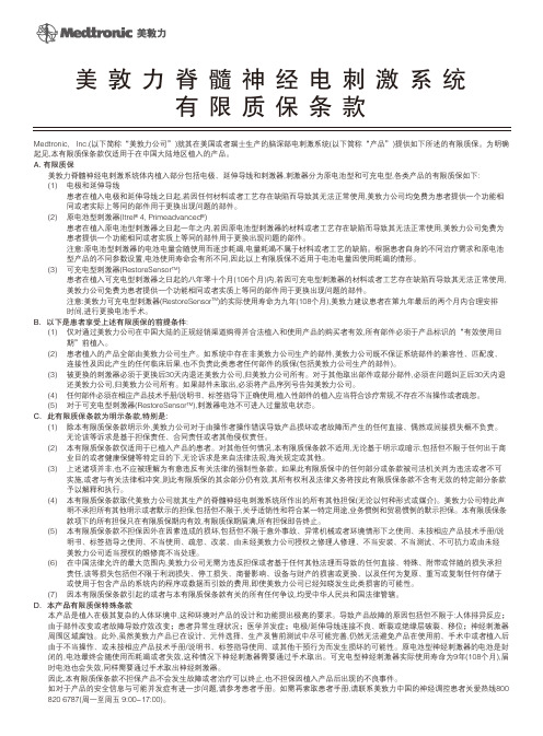
Medtronic, Inc.(以下简称“美敦力公司”)就其在美国或者瑞士生产的脑深部电刺激系统(以下简称“产品”)提供如下所述的有限质保。
为明确起见,本有限质保条款仅适用于在中国大陆地区植入的产品。
A. 有限质保美敦力脊髓神经电刺激系统体内植入部分包括电极、延伸导线和刺激器,刺激器分为原电池型和可充电型,各类产品的有限质保如下:(1) 电极和延伸导线患者在植入电极和延伸导线之日起,若因任何材料或者工艺存在缺陷而导致其无法正常使用,美敦力公司均免费为患者提供一个功能相 同或者实际上等同的部件用于更换出现问题的部件。
(2) 原电池型刺激器(Itrel ® 4, Primeadvanced ®)患者在植入原电池型刺激器之日起一年之内,若因原电池型刺激器的材料或者工艺存在缺陷而导致其无法正常使用,美敦力公司免费为 患者提供一个功能相同或者实质上等同的部件用于更换出现问题的部件。
注意:原电池型刺激器的电池电量会随使用而逐步耗竭,电量耗竭不属于材料或者工艺的缺陷。
根据患者自身的不同治疗需求和原电池 型产品的不同参数设置,电池使用寿命会有所不同,因此以上有限质保不适用于电池电量因使用耗竭的情形。
(3) 可充电型刺激器(RestoreSensor TM )患者在植入可充电型刺激器之日起的八年零十个月(106个月)内,若因可充电型刺激器的材料或者工艺存在缺陷而导致其无法正常使用, 美敦力公司免费为患者提供一个功能相同或者实质上等同的部件用于更换出现问题的部件。
注意:美敦力可充电型刺激器(RestoreSensor TM )的实际使用寿命为九年(108个月),美敦力建议患者在第九年最后的两个月内合理安排 时间,进行更换电池手术。
B.以下是患者享受上述有限质保的前提条件:(1) 仅对通过美敦力公司在中国大陆的正规经销渠道购得并合法植入和使用产品的购买者有效,所有部件必须于产品标识的“有效使用日 期”前植入。
美敦力临时起搏器说明书PPT课件

2 19 PACE SENSE 3
4
18 3 17 16
0.1 5 10 30 80 120 200
RATE
min -1
5
v
OUTPUT
15
ASY
20
10
1
0.5
6
SENSITIVITY源自mv1.5078
14
1180
PULSE WIDTH
2
概述
PACE
SENSE
• 单腔临时起搏器
–按需/同步起搏
30
80
120
200
RATE
min -1
0.1
5
10
(VVI, AAI)
–·非同步起搏 (VOO, AOO)
OUTPUT
v
ASY
20
10
1
0.5
SENSITIVITY
mv
• 起搏分析仪
–测量P/R波
1.50
1180
PULSE WIDTH
(测感知阈值)
EMERGENCY
MEASURE
–测量起搏阈值 –测量起搏阻抗
PAUSE
OFF
ON
MEDTRONIC ® 5318
Temporary Pacemaker/ Implant Tool
–膈肌刺激试验
Education Department, Greater China Region 3
规格
模式 频率 AAI,AOO,VVI,VOO 30-200/min
临时起搏特点
• 起搏/感知指示灯 起搏 = 绿色
感知 = 橘黄色
- 1、下载文档前请自行甄别文档内容的完整性,平台不提供额外的编辑、内容补充、找答案等附加服务。
- 2、"仅部分预览"的文档,不可在线预览部分如存在完整性等问题,可反馈申请退款(可完整预览的文档不适用该条件!)。
- 3、如文档侵犯您的权益,请联系客服反馈,我们会尽快为您处理(人工客服工作时间:9:00-18:30)。
⏹请病人家属或者医护人员记住以下几点:⏹通读本手册以使您可以帮助病人使用本产品生活。
⏹请务必告知医护人员病人拥有一个植入式脑起搏器并且告知其位置。
如果医务人员有任何疑问可致电美敦力 1-800-510-6735。
⏹请常备病人的医生和(译者注:欧美每个人均备有私人医生)以便解答任何问题。
同时,请常备美敦力病人服务部(1-800-510-6735)的以防您或者医务人员有任何疑问。
在出现需要急救的情形时,请拨打911(译者注:相当于中国的120)。
一个致力于病人的公司美敦力创建于1949年,创建人为Earl Bakken(一个电子工程专业的毕业生)以及其堂兄弟Palmer J.Hermundslie。
如今,美敦力公司是世界医疗科技的领头羊,本公司探索重建健康,延长生命,消除病痛的疗法。
美敦力公司从明尼阿波利斯市(译者注:美国明尼达州一城市)一个600平米的车库起家,如今已发展成为一所世界性的公司,为全球超过120个国家的客户提供服务,每年,有数百万病人采用美敦力公司的产品或者疗法。
我们每年投资近5亿美元用于研发,同世界上最好的医生和科学家紧密合作。
这一切都是为了提高我们的产品和疗法,并且开发新产品。
虽然我们是一所大公司,但单个病人的需求依旧是我们该做什么,以及怎样做的驱动力。
我们的愿景是改善您的生活质量。
这本小手册正是我们的愿景的一个细小的体现。
欢迎加入美敦力大家庭,祝您早日康复。
(译者注:目录略)1. 术语解释:幅度:幅度是针对您的特定疗法中的起搏器强度。
幅度以伏特为单位。
幅度几个可以被临床医师调节以改善您的帕金森症状的设置量之一。
电池:为您的脑起搏器提供能源的部分。
神经起搏器的电池需要平均2-5年充电一次。
临床编程器:一个用于为Activa系统(译者注:本脑起搏器的软件系统)编程的微电脑。
医生可以用它来改变不同疗法的设置。
计算机轴向体层扫描(CT):一项可以看清大脑部或者身体其他部分的检查,可以看到无法被X光扫描到的区域。
禁忌:医学上指的是病人必须禁用的措施、设备或者药品等等,应为它们对病人弊大于利。
电磁干扰:足以影响或者扰乱您的治疗的电场或者磁场能量。
自发性震颤:一项唯一症状为由肌肉节律性收缩引起的震颤。
常发生于手臂、头部、腿部、躯干或者声音。
X光透视检查:一项可以看清部器官运动的X光措施。
左旋多巴:用于治疗帕金森病的主要药物。
磁共振成像:一项运用磁场扫描而得到您的身体解剖图片。
“开”期(on time):由您的帕金森症状而使您获得轻松感的时候。
伴随有运动障碍的“开”期:由您的帕金森症状而使您获得轻松感,但伴随有由帕金森药物引起的不可控制的运动。
帕金森病:拥有四个典型症状的运动失调:震颤(无意识的节律性震动),僵硬(四肢僵硬),运动徐缓/运动不能(运动缓慢/没有运动)以及姿势不稳定(在平衡和身体协调方面的问题)。
帕金森病是由大脑中缺乏一种叫做多巴胺的物质而引起的。
刺激:向大脑细胞传送电信号,这些电信号或许可以阻断由大脑中控制运动的区域所处理的错误的消息。
刺激测试:在Activa System系统被植入的阶段对脑部刺激进评估以测试它能在多大程度上控制您的症状。
超声波:利用超声波进行诊断或者其他达成其他医疗目的。
2. 信息说明设备用途美敦力Activa疗法包括Activa帕金森控制疗法和Activa震颤控制疗法。
请参阅“附录:处方信息”在本手册的第100页查询适用症。
帕金森症控制疗法Activa帕金森控制疗法将电刺激送达大脑中的相关区域以帮助治疗重症帕金森病。
电刺激可以同时被送到您大脑的两边以同时帮助缓解身体两侧的症状。
如果左旋多巴对您的症状有作用但是他对您的症状的缓解作用正变得越来越小甚至不起作用的时候,那么,你正是这项疗法的适用者。
震颤控制疗法Activa震颤控制疗法将电刺激送达大脑中以帮助治疗原发震颤或者由帕金森病引起的震颤。
电信号仅被送到身体的一侧用于治疗一只胳膊的震颤。
本系统用于被诊断出患有特发性震颤或者药物不足以控制的足以致残的帕金森震颤。
产品说明书本脑刺激系统被直入您的体。
一个控制磁铁或者治疗控制器用于打开或者关闭疗法,Activa System 系统由三个主要部分组成:铅芯(lead):铅芯由装在一个塑料管中的四根导线组成,它将刺激信号传导给四个电极(电极由白金环构成)到达脑组织铅芯大约有四英寸(一英寸等于2.54厘米)被植入大脑,铅芯的其余部分(大约15英寸)被植入到头皮下。
至于您拥有一个还是两个铅芯取决于您的医疗情况。
延伸线:延伸线是由装在一个塑料管中的连接到神经刺激器的四根导线组成,它被连接到了铅芯的末端。
延伸线就位于耳朵的背后(或者在你的医生认为的最好的地方)。
延伸线隧穿了脖子直至胸部的皮肤直到连接到神经刺激器。
对于每一个铅芯都会有一个延伸线连接。
神经刺激器:神经刺激器包含一块为整个系统提供能源的电池,由神经刺激器控制发出电刺激信号,它被植入到胸部靠上的部位的皮肤下面。
Kinetra model 7428型神经刺激器大约有3英寸长,2.4英寸高,0.6英寸厚。
Soletra Model 7426型和ItrelⅡModel 7424型神经刺激器有大约2.4英寸长。
2.2英寸高,0.6英寸厚。
图2.1 脑起搏器系统植入体的局部图识别您的Activa 系统植入您体的Activa系统的类型取决于您的医疗状况,帕金森病患者需要脑部刺激以抑制全部身体两侧的症状,特发性震颤和帕金森震颤患者需要脑部刺激以抑制身体一侧的震颤症状。
在接下来的篇幅里,将会对不同种类的Activa系统各自详细介绍。
帕金森控制疗法(Kinetra)如果您的身体两侧同时接受电刺激的作用,那么您体可能植入了Kinetra Model 7428型神经刺激器,同时您体植有两根铅芯和两条连接到神经刺激器的延伸线。
图2.2植入式Activa脑刺激系统(Kinetra)帕金森控制疗法(Soletra)如果您因为帕金森病接受影响身体两侧的电刺激,您可能拥有两个植入体的Soletra Model 7426 型神经刺激器,同时您体植有两根铅芯和两条分别连接到两个神经刺激器的延伸线。
图2.3 植入式Activa 脑刺激系统(Soletra)震颤控制疗法(Soletra 或 Itrel Ⅲ)如果您因特发性震颤或帕金森震颤接受电刺激,您体可能植入了一个Soletra Model 7426或一个Itrel II Model 7424型神经刺激器。
同时您体植有一根铅芯和一条连接到神经刺激器的延伸线。
图2.4 植入式Activa脑刺激系统脑刺激系统工作原理您的一些症状是由大脑发出的不正常的信息引起的,您的脑刺激系统就是将温和的电刺激送达大脑中控制运动的区域,电刺激将会阻断部分由大脑送出以及送达大脑的信息,这样或许可以减轻您的症状。
您所接受的疗法可以帮助控制症状,但却不能根治。
当您打开您的脑刺激系统,它发出刺激信号,您的症状或许会减轻,但当您关掉它时,以前的症状也会随之而来。
禁忌在如下情形时,不能使用Activa 脑刺激系统:即将进行透热疗法(深热处理)的患者。
请务必提醒你的治疗人员你身体的任何部位绝对不能进行任何短波、微波或者超声波透热疗法,因为你有一个植入式的神经刺激系统,热透疗法的能量可能会转移到你的植入式神经刺激系统,可能会引起严重的组织损伤甚至严重伤害直至死亡。
⏹热透疗法也可能损坏部分神经刺激系统,这可能会使你的神经刺激系统失去疗效,这时你需要做一次额外的手术去移除损坏的器件,在进行热透疗法时,无论你的神经刺激器是否开机,都会造成损坏。
⏹即将进行全身、头部或者扩展到胸部的头部核磁共振成像的患者,戴着本设备进行核磁共振成像检查时可能会因部件受热造成组织损伤,特别是铅芯上的电极,会导致永久性的伤害,包括昏迷,瘫痪甚至死亡。
⏹进行刺激测试失败的患者不能使用。
⏹无确操作神经刺激器的患者不能使用。
风险Activa疗法的风险包括:手术的风险,副作用以及本器械引起的并发症。
手术的风险植入神经刺激器的手术带有同其他脑部手术同样的风险,这些风险包括:⏹可能引起瘫痪,昏迷甚至死亡。
⏹可能造成脑大出血(中风)。
⏹泄漏脑周围的液体。
⏹可能会导致中风突然发作。
⏹可能会造成创口感染。
⏹可能会发生对植入材料的过敏反应。
⏹可能会导致暂时或永久的神经系统并发症。
⏹可能会导致意识错乱或者注意力方面的问题⏹可能会导致手术部位的疼痛⏹可能会导致头痛可能的副作用⏹脑部刺激可能带来的副作用如下:⏹感觉异常⏹病人病情的暂时恶化⏹语言问题,例如发音困难(构音困难)以及构词困难(言语障碍症)⏹视觉问题(复视)⏹头晕(常有失衡感)⏹脸部和肢体肌肉无力或者局部瘫痪(麻痹性痴呆)⏹非正常、不自主的运动(舞蹈症,肌力异常,运动障碍)⏹运动障碍或失去身体协调⏹常有震击和震动感⏹感觉麻木(感觉迟钝)设备可能引起的并发症⏹在脑刺激系统植入的部位可能出现疼痛,创口难以愈合,或者创口感染⏹脑刺激系统的部件可能磨破你的皮肤。
由此可能引发感染或者瘢痕形成⏹铅芯或者铅芯和延伸线之间的连接点可能移动,你需要手术去重新调整他们的位置⏹Activa疗法可能会因为机械或者电气方面的问题停止,而这些都需要进行手术。
神经刺激器的电池平均每2-5年需要更换一次。
⏹你的身体可能会对脑刺激系统产生过敏反应同时你的身体可能排斥本系统(作为一个外来物)⏹编程参数或者脑刺激系统的部件的故障可能会引起组织损伤益处对患有帕金森病病人的益处Activa疗法通过将电刺激送入大脑以治疗重症帕金森病,电刺激可以被传送到大脑的两侧以缓解身体两侧的症状。
Activa疗法可能会在以下方面带来益处:⏹增加你的“开”期时间⏹减少你带有动力障碍的“开”期时间⏹改善你的帕金森病症状但却不能根治。
当你打开你的脑刺激系统,它发出刺激信号,你的症状或许会减轻。
对于患有特发性震颤或者帕金森震颤的患者的益处Activa疗法传送电刺激到脑部区域以帮助治疗患有特发性震颤或者与帕金森病相关的震颤的患者,电刺激被传送到大脑的一侧以帮助缓解你身体相应一侧的症状。
你的疗法只能帮助控制震颤但却不能根治,当你打了开脑刺激系统,它会传送可以减少你的震颤的电刺激,当你关闭系统时,震颤也随之而来对你的植入手术的期待(What to Expect From Your Implant Procedure)(译者注:本句较难翻译可能词不达意)以下是关于Activa脑刺激系统如何被植入你的身体的一些总体信息,你的私人医生可能会给你提供更多的关于你的植入手术的特定信息。
在手术前手术前一天的晚上,你将会被告知停止使用一切药品,这样做是为了使得Activa疗法对你的症状的作用能被最好的确定,你将会在手术前一天的晚上或者手术当天的早上入院,在手术之前你需要将头发全部剃掉以帮助预防感染。