FCM2000质量流量计中文手册(V 0.7)
科氏力质量流量计

9
z 节省空间,设计坚固耐用。
11
z 流量范围广;流量计口径从„S“ (DN 1,5 [1/16”]) 至 „
13
L“ (DN 150 [6”])。
14
z 多种过程连接可供选择。
15
z 两个独立的电流输出,用于输出流量与密度信号,也可通
16
过一路脉冲输出。
20
z 触点输入与输出。
21 22 23 24
具有数字信号处理器(DSP)的质量转换器
FCM2000 的转换器包含一个数字信号处理器(DSP),可以 用它进行质量流量与密度值的最高精度测量。科氏力传感器信 号被立即转换为数字信息,而无须任何中间模拟步骤。
通过新型DSP转换器,可以实现优异的长期稳定性与可靠性、 以及快速的信号处理能力。
流量计传感器及转换器的自诊断功能加上绝对零点稳定性是 其根本优势,这对于保证测量的可信度十分必要。
流量计测量管始终在进行振动。工作条件下的振动频率与测量 管几何形状、流量计材料特性以及测量管中流体(也在振动) 的质量具有函数关系。从而可以准确地测量所计量流体的密 度。总之,使用科氏力质量流量计,可以同时测量质量流量、 流体密度以及温度。
仪表设计
流量计传感器由两个单根的测量管构成,该测量管平行放置, 流体在其中流动。特别设计了一种抗扭曲安装结构(连接流量 计的进口与出口),以使测量管与外部的力及力矩隔绝。
D184S068U02
概述
FCM2000 是一种经济而简单的ABB质量流量计,具有最新的
2
DSP转换器,后者与流量计传感器可一体安装或分体安装。一
3
体化的设计降低了安装与电缆铺设费用。可在流量计处直接查
3
看流量信息,并可按照更加节省空间的方式把流量计安装在您
FCM-4说明书(频率输入)N

FCM-IV流量测控仪使用说明书上海煤科实业有限公司Shanghai Coal Science & Technique Industrial Co. Ltd.请您仔细阅读该说明书,以便正确使用仪表。
1概述FCM-IV型流量测控仪可与任何具有脉冲输出的流量传感器(变送器)配套使用,其特点如下:1.1同时显示瞬时流量和累积流量;1.2准确地进行流量定量控制;1.3四路继电器触点输出;1.4历史报警记录查询;1.5定时或随时打印累积流量和瞬时流量;1.6可提供直流电流或电压输出,与调节系统联用可实现流量的自动控制;1.7测量数据断电保存;1.8时钟功能;本仪表与相应的传感器(变送器)配套使用,可广泛应用于石油、化工、食品、船舶等行业中对管道液体流量进行测量,以及液压机械、液压试验设备中流体流量的在线检测与控制。
2主要技术参数2.1误差:累积流量基本误差:≤0.1% FS ± 1字瞬时流量基本误差:≤0.3% FS ± 1字定量控制基本误差:≤0.1% FS ± 1字2.2显示范围:累积流量: 0.000~9,999,999L(T)瞬时流量:四位数码管显示,0.000~9999L/min(T/h)2.3输入信号:正弦波或方波,幅值:5V~24V,频率1~10,000Hz2.4输出信号:模拟量输出: 4~20mA (≤800Ω)或 1~5V (≤30 mA)精度 1%开关量输出:继电器触点输出(AC220V/0.1A,DC24V/1A,阻性负载)馈电输出: DC5V或12V (≤30 mA)通讯: RS-2322.5打印:直接配串行TP微型打印机,通讯方式为RS-2322.6报警方式:可选择继电器上、下限报警输出,LED报警指示2.7流量定量控制方式: ON/OFF带回差,可设置流量定量控制值,由继电器触点输出,启、停阀或泵2.8通讯方式:双向RS-232口2.9设定方式:面板轻触式按键数字设定,设定值断电永久保存2.10保护方式:断电累积流量值保持大于一年2.11工作条件:环境温度:0~40℃,相对湿度:≤85%2.12电源: 220V±10%AC2.13尺寸:外形尺寸: 160×80×140(mm)(宽×高×深)开孔尺寸: 152×76 (mm)(宽×高)3 工作原理(见图1)流量传感器发出的脉冲信号fin,经滤波整形后,送入单片机计数器,进行数据采集,然后在七位数码管上显示累积流量,在四位数码管上显示瞬时流量,并且输出表示瞬时流量的4~20mA 电流值。
FL-2000系列精密流量计说明书

The FL-2000 Series offers a wide variety of precision flowmeters for use in medical, industrial, chemical, and laboratory applications at an economical price. Units are available with or without valves.Acrylic FlowmetersB-15aFL-2000 SeriesSpeciFicationSaccuracy:Models FL-2001–FL-2025: ±5% F.S. Models FL-2031–FL-2069: ±3% F.S. Models FL-2071–FL-2128: ±2% F.S.Float: Black glass stainless steel Body: Clear acrylicSeals: Buna “O” Rings with brass or PVC fittings FKM “O”-Rings with stainless steel fittingspressure: 100 psig max @ 21°C (70°F)temperature:65°C (150°F) max @ 0 psigFittings: Brass std; stainless steel optional except for FL-2071 through FL-2128, which have 1 NPT PVC fittings onlyValves: Models FL-2001 throughFL-2069: brass standard; stainless steel cartridge type (optional)FL-2071 through FL-2128: Optional plastic in-line gateU e asy-to-Read english or Metric Scales U W ater Ranges from 4 ccM to 20 GpM, air Ranges from 40 ccM to 4000 LpM U t hreaded Brass inserts for Quick installation U e asy Disassembly and assembly for Maintenance U D urable one-piece clear acrylic construction U S table, easy-to-Read Float U S uperior Quality appLicationS U a ir Sampling equipment U a quaculture U D esalinization equipment U G as analyzers U M edical Systems U p hoto processing equipment U W ater treatment andDistribution SystemsFL-2013 air, shownsmaller than actual size.FL-2066-nV Water, shownsmaller than actual size.B(13.5)B-15bFL-2091 through FL-2128 DimensionsFL-2097, shown smaller than actual sizeTo order with plastic integral gate valve, add suffix “-V” to model number for additional cost for FL-2090 Series, and FL-2120 Series.For optional 10-point NIST certificate add suffix, “-NIST” to the model number, for additional cost and two weeks to the standard lead time.Ordering Example: FL-2095, flow meter , 100 to 1400 LPM Air FL-2127-V, flow meter , 4 to 36 LPM water, with valves.Units are standard without valves.To order with plastic integral gate valve, add suffix “-V” to model number for additional cost.For optional 10-point NIST certificate add suffix, “-NIST” to the model number for additional cost and two weeks to the standard lead time.Ordering Examples: FL-2075, flow meter valve, 100 to 1400 LPM air.FL-2080, flow meter valve, 2 to 19 LPM water.FL-2041-nV, shown smaller than actual size.FL-2053, Water,shown smaller thanactual size.FL-2066-nV, shown smaller than actual size.To order with stainless steel valve, add suffix “-SS” to model number for additional cost.To order without a valve, add suffix “-NV” to model number and subtract from cost.For optional 10-point NIST certificate add suffix, “-NIST” to the model number, for additional cost and two weeks to the standard lead time.Ordering Examples: FL-2036, economical flow meter , with brass valve, 14 to 150 SCFH Air.FL-2036-NV , economical flow meter ,without brass valve,14 to 150 SCFH Air.BFL-2060, air, shown smaller than actual size.Dual scales supplied std: SCFM/SCFH, GPM/GPH and LPM/LPH To order with stainless steel valve, add suffix “-SS” to model number for additional cost.To order without a valve, add suffix “-NV” to model number and subtract from cost.For optional 10-point NIST certificate add suffix, “-NIST” to the model number, for additional cost and two weeks to the standard lead time.Ordering Examples: FL-2060, flow meter with brass valve, 0.5 to 5 SCFM. FL-2069-NV , flow meter no valve 2 to 20 LPM.FL-2091, air, shown smaller thanactual size.B-15cFL-2021-nV, Water, shown larger than actual size.Units come standard with brass valves and operator’s manual.To order with stainless steel valves, add suffix “-SS” to model number for additional cost. To order without a valve, add suffix “-NV” to model number and subtract from cost.For optional 10-point NIST certificate add suffix, “-NIST” to the model number, for additional cost and two weeks to the standard lead time.Ordering Examples: FL-2005, economical flow meter with brass valve, 2 to 20 SCFH air. FL-2005-NV , economical flow meter without valve, 2 to 20 SCFH air.accuracy: ±5% Full Scale panel MountB-15d。
超声波流量计说明书

MKflo-2000F 系列中文版超声波流量计说明书
§3.7 怎样实现流量累积器清零 .... 59 §3.8 怎样恢复出厂设置 .......... 59 §3.9 怎样使用阻尼器稳定流量显示 60 §3.10 怎样使用零点切除避免无效累积 ............................... 60 §3.11 设置零点提高测量精度 ..... 61 §3.12 修改仪表系数(标尺因子)进行 标定校正 ....................... 62 §3.13 密码保护(加锁与开锁) ... 63 §3.14 怎样使用打印机 ........... 64 §3.15 怎样使用 4~20mA 电流环输出 64 §3.16 怎样输出模拟电压信号 ..... 65 §3.17 怎样输出累积脉冲 .......... 66 §3.18 怎样使用 OCT 输出 ........ 67 §3.19 怎样修改日期时间 ......... 67 §3.20 怎样调整 LCD 显示器 ...... 67 §3.21 怎样使用 RS232 串行口 ..... 68 §3.22 怎样查看每日、每月、每年流量 ............................... 68 §3.23 怎样对模拟输出进行校准 ... 69 §3.24 查看电子序列号和其他细节 . 71 四 命令/显示窗口详解 ............. 72
超声波流量计说明书
SCT
超声波流量计说明书
(固定式、便携式通用)
MKflo-2000F 系列中文版超声波流量计说明书
目录 一 概述 ........................... 8
§1.1 引言 ....................... 8 §1.2 SCT 的特点 ................. 9 §1.3 工作原理 .................. 12 §1.6 可选备件 .................. 14 §1.7 产品型号编码规则 ........... 15 §1.8 接线图..................... 16 §1.9 性能指标 .................. 17 二 开始安装测量 .................. 21 §2.1 开箱检查 .................. 21 §2.2 供电电源 .................. 21
AWM 2000 系列微桥质量气流传感器说明书
681-800-537-6945 USA 1-815-235-6847 International1-800-737-3360 CanadaFEATURESɀBidirectional sensing capability ɀActual mass air flow sensingɀLow differential pressure sensing The AWM2000 Series microbridge mass airflow sensor is a passive device com-prised of two Wheatstone bridges. The heater control circuit in Figure 1is re-quired for operation per specifications.The sensing bridge supply circuit in Fig-ure 2 is also required for operation per specifications. These two circuits are not on board the package and must be sup-plied in the application. The differential amplifier in Figure 3 is a useful interface for the sensing bridge. It can be used to introduce the gain and to introduce volt-age offsets to the sensor output as refer-enced in Equation 1.Note: For applications sensing hydrogen or helium, see Application Note 3, page 131.Figure 1Heater Control CircuitFigure 2Sensing Bridge Supply CircuitFigure 3Differential Instrumentation Amplifier CircuitEquation 1:V o ⍧2R 2+R 1R 4V 2-V 1+V offset()()()R 1R 3where V offset ⍧V S()R 6R 6+R 51-800-537-6945 USA 1-815-235-6847 International 1-800-737-3360 Canada 691. Output Voltage is ratiometric to supply voltage.2. Temperature shifts when sensing differential pressure correlates to the density change of the gas over temperature.See Application Note 1.3. Maximum allowable rate of flow change to prevent damage: 5.0 SLPM/1.0 sec.MOUNTING DIMENSIONS (for reference only)Airflow701-800-537-6945 USA 1-815-235-6847 International 1-800-737-3360 CanadaOUTPUT FLOW VS INTERCHANGEABILITY (Note 1)Performance Characteristics @10.0 ±0.01VDC, 25°C AWM2100V AWM2150VAWM2200V(Note 2)AWM2300V Press.Flow Nom.Tol.Press.Flow Nom.Tol.Flow Press.Nom.Tol.Press.Flow Nom.Tol.mBar sccm mV±mVȖBar sccm mV±mVsccm ⍯H 2O mV±mVmBar sccm mV±mV0.4920044.50 4.25533014.0 2.5120 4.0031.75 3.50 3.4100055.50 3.700.3515038.75 3.0036209.5 1.590 3.0026.75 2.50 2.480052.90 3.500.2110030.00 1.501710 5.0 1.560 2.0020.00 1.20 1.865050.00 2.500.095016.50 2.509.85 2.5 1.030 1.0011.20 1.800.8340042.50 3.000.000.00 1.007.44 2.0 1.000.000.001.000.3120029.20 3.20−0.09−50−16.50 4.50 6.23 1.5 1.0−30−1.00−11.20 3.0000.00 1.00−0.21−100−30.00 5.0052 1.0 1.0−60−2.00−20.00 3.30−0.31−200−28.9015.00−0.35−150−38.807.65 2.510.50.8−90−3.00−26.75 5.30−0.83−400−41.2026.00−0.49−200−44.509.75000.00.6−120−4.00−31.757.00−1.6−600−48.2029.50−9.8−5−2.5 2.0−2.4−800−52.2032.50−53−30−14.05.0−3.4−1000−55.0036.00Notes:1.Numbers in BOLD type indicate calibration type, mass flow or differential pressure.Tolerance values apply to calibration type only.2.Differential pressure calibrated devices are not recommended for flow e flow calibrated devices for flow measurement.OUTPUT CURVES。
蓝白科技 F-2000数字桨盘流量计说明书

Video link:NEMA 4XFor more help and information regarding F-2000, please visit or scan this QR code.F-2000Digital Paddlewheel Flow Meter> Easy to read 8 digit LCD, up to 4 decimal positions > Flow rate and Total flow display> AC/DC transformer or battery operated (RT models only). 4 AA batteries > Factory programmed with calibration certificate > Front panel security lockout> 4-20ma and 0-10VDC output models > Batch Processing and Flow Rate Alarms®HighlightsFlow rangeFull Scale Accuracy Power supply .4 - 8,000 GPM 1 to 27,000 LPM Pressures300 PSI (20 bar)Pressure dropWarranty0 - 8 PSI(varies per model)+/- 1%15-24 VDC115V/230V60z, 220V/50Hz Battery operated1 YearFeaturesMolded FittingsSaddle Mount FittingsPVC FittingsAvailable Models2Engineering SpecificationsDigital Paddlewheel Flow MeterPerformanceDimensionsF-2000Saddle FittingsPipe Size A B 1-1/2”(50mm)4-1/2” 3-3/16” 2”(63mm)4-1/2”3-3/16”3”(90mm)4-1/2”3-3/16”4”(110mm)4-1/2”3-3/16”6”(160mm)4-3/8”3-3/16”8”(200mm)4-3/8”3-3/16”10”(250mm)4-1/2”4-1/2”12”(315mm)4-1/2”4-1/2”Molded FittingsPipe Size A B 3/8”3-3/4” (95)4-3/4” (121)1/2”3-3/4” (95)5-1/8” (130)3/4”4” (102)5-1/4” (133)1”4” (102)5-5/8” (143)1-1/2”4-1/2” (114)6-1/2” (165)2”4-3/4” (121)6-3/4” (171)Pipe SizeA B 1”6”4”1-1/2”6-5/8”4-1/2”2”7-1/8”4-3/4”PVC Saddles & PVC TeesPVDF Saddles & SS TeesSTATIC PRESSURE PSI(BAR)Maximum Working Pressure300 PSI (20 bar) @ 70 °F (21 °C)Maximum Fluid Temperature 200 °F (93 °C) @ 0 PSI (PVDF saddles and PP Molded fittings)140 °F (60 °C) @ 0 PSI (PVC saddles and PVC Tee fittings)NOTE: Temperature rating of F-2000 only. Actual pipe rating mary vary.Maximum Ambient Temperature 14 °F to 110 °F/ -10 °C to 43 °C Maximum Pressure Drop up to 8 PSI (varies per model)Full Scale Accuracy +/- 1%Power Requirement15 VDC Nominal (15 - 24 VDC Absolute)Model RT units only 4 AA batteries or 15 - 24 VDC plug-in transformer All units 15 - 24 VDC (plug-in transformer supplied)Signal Distance AC sine wave sensor = 200 ft(60 m)Optional Hall Effect sensor = 1 mile(1.6 km)Signal Cable3 conductor shielded. Included 25 ft(7.6 m)(Option for 50 ft and 100 ft)Approximate Shipping Weight4 lb. (1.8 kg)Enclosure NEMA 4X (IP56)RoHS CompliantYesPP3Materials of ConstructionF-2000Ordering InformationMolded In-Line Pipe FittingsTEE Pipe FittingsSaddle Mount Pipe FittingsPipe Size GPM Flow Range LPM Flow Range M 3/HR Flow Range OZ/MinFlow RangeModel Number M/NPTMNPT MBSPT 3/8".8 to 830 - 300.2 - 1.8106 - 105838M138MB13/8”.4 to 4 1 - 100.1 - 0.635 - 35338M238MB21/2" 2 to 207 - 700.4 - 4.2247 - 246950M150MB13/4" 3 -3011 - 1100.7 - 6.6388 - 388075M175MB11" 5 to 5020 - 200 1.2 - 12705 - 705410M110MB11-1/2" 6 to 6025 - 2501.5 - 15885 - 881815M215MB22”10 to 10040 - 400 2.4 - 241411 - 1410820M320MB32”20 to 20070 - 7004.2 - 422469 - 2468920M420MB4Pipe Size IPSGPM Range M 3/HR Flow Range Model Number Sch 40Sch 801-1/2"15 - 150 3.5 - 34.515K415K8315mm2700 - 27000162 - 162031A0Pipe SizeGPM Range LPM Range Model NumberSolvent Weld PVC Tee1" 6 to 6025 - 25010AT 1-1/2"15 to 15060 - 60015AT 2"30 to 300100 - 100020AT 3"60 to 600230 - 230030ATSaddle material:PVDF ( 1-1/2”, 2”, 3”, 50mm, 63mm, 90mm sizes) PVC (other sizes)In-Line Molded Tee: Polypropylene Sensor, paddlewheel, axle: PVDFSensor O-ring seals:Viton (optional EP)TDS# 85000-171 REV 4202306195300 Business Drive, Huntington Beach, CA 92649TEL714-893-8529|FAX714-894-9492||********************F-2000 Model Number MatrixF-20005300 Business Drive, Huntington Beach, CA 92649 TEL714-893-8529|FAX714-894-9492||********************VariationsRT = Flow Rate and TotalizingAO = Analog Output, Flow Rate and Totalizing PC = Batch Processing, Flow Rate Alarm, Proportional Metering, Flow Rate and TotalizingAP = Analog Output, Batch Processing, Flow Rate Alarm Proportional Metering, Flow Rate Alarm and Flow Totalizing FC = Flow Sensor - AC Coil - 200 ft. range FH = Flow Sensor - Hall Effect - 1 mile rangePipe Sizes M/NPTImperial Pipe Sizes Metric Pipe Sizes 38 = 3/8" IPS 05 = 50mm 50 = 1/2" IPS 06 = 63mm 75 = 3/4" IPS 07 = 75mm 10 = 1" IPS 09 = 90mm 15 = 1-1/2" IPS 11 = 110mm 20 = 2" IPS 16 = 160mm 25 = 2-1/2" IPS 20 = 200mm30 = 3" IPS 25 = 250mm (PN10 only)40 = 4" IPS 31 = 315mm (PN10 only)60 = 6" IPS 80 = 8" IPS 100 = 10" IPS 120 = 12" IPSSaddle Pipe Fitting TypeSADDLE, SCH40 (I.P.S.) PVC or IRON pipeK4 = 1-1/2", 2", 3" PVDF A4 = 2-1/2”, 4”, 6”, 8” PVC A4 = 10”, 12” PVC SADDLE, SCH80 (I.P.S.) PVC pipeK8 = 1-1/2", 2", 3" PVDF A8 = 2-1/2”, 4”, 6”, 8” PVC A8 = 10”, 12” PVC SADDLE, PN10 METRIC (DIN 8062) pipeK0 = 50mm, 63mm, 90mm PVDF A0 = 75, 110, 160, 200 PVC A0 = 250,315mm PVC SADDLE, PN16 METRIC (DIN 8062) pipeK6 = 50mm, 63mm, 90mm PVDF A6 = 75, 110, 160, and 200, PVCInline Pipe Fitting TypeINLINE INJECTION MOLDED PP AMERICAN M/NPTM1 = Range #1, M2 = Range #2M3 = Range #3, M4 = Range #43/8", 1/2", 3/4", 1" M/NPT polypropylene 1-1/2" M/NPT polypropylene 2" M/NPT polypropylene INLINE INJECTION MOLDED PP BRITISH M/BSPTMB1 = Range #1, MB2 = Range #2MB3 = Range #3, MB4 = Range #43/8", 1/2", 3/4", 1" M/BSPT polypropylene 1-1/2" M/BSPT polypropylene 2" M/BSPT polypropylene INLINE INJECTION MOLDED TEE PVC SLIP/SOCKETAT = 1", 1-1/2", 2" Female slip glue/weld 3” Female slip glue/weldCalibration UnitsGM = U.S. Gallons per minute LH = Liters per hour GH = U.S. Gallons per hour LD = Liters per dayGD = U.S. Gallons per day MH = Cubic Meters per hour OM = U.S. Ounces per minute IM = Imperial Gallons per minute AD = Acre Feet per day IH = imperial Gallons per hourLM = Liters per minuteCalibration Range (see pipe fitting detail)1 = Range 13 = Range 32 = Range 24 = Range 4Display MountingS = Meter Mounted on AC Coil Sensor P = Meter Panel Mounted, AC Coil Sensor, 200 ft. range, includes 25 Ft. of cable H = Meter Panel Mounted, Hall Effect Sensor, 1 mile Range, includes 25 ft. of cable X = Sensor only (without Display Meter)PowerB = Battery Holder with 4 AA cells1 = U.S. Transformer, AC 115V60Hz/15Vdc, NEMA 5/15 plug2 = Europe Transformer, AC 230V50Hz/15Vdc, CEE 7/VII plug3 = U.S. Transformer, AC 230V60Hz/15Vdc, NEMA5/15 plug X = No Selection (Customer must supply power)OptionP = No pipe fitting*50FT = 50 feet of signal cable 100FT = 100 feet of signal cableRTSB38M1GM1-PSample Model NumberOptional Accessories and Components 71000-294 Panel Mount Kit Bracket71000-514 Mounting Conversion Kit, Sensor Mount to Panel Mount.71000-301 Wall Mount Adapter Kit. Cable Not Inlcuded.71000-302 Wall or Pipe Mounting Kit (3/8” - 1.5 “ Pipe). Cable Not Included.71000-303 Wall or Pipe Mounting Kit (2” Pipe). Cable Not Included. 71000-304 Wall or Pipe Mounting Kit (3” Pipe). Cable Not Included. 71000-305 Wall or Pipe Mounting Kit (4” Pipe). Cable Not Included. 71000-306 Wall or Pipe Mounting Kit (6” Pipe). Cable Not Included. 71000-307 Wall or Pipe Mounting Kit (8” Pipe). Cable Not Included. 71000-414 Wall or Pipe Mounting Kit (10” Pipe). Cable Not Included. 71000-415 Wall or Pipe Mounting Kit (12” Pipe). Cable Not Included. 71000-322 Battery Back-up KitSee Spare Parts or Instruction Manual for more options.。
FX2000流量积算仪

II
目录
目
录
第 1 章 仪表概要 ........................................................................................................... 4 1.1 仪表介绍 ............................................................................................................... 4 1.2 仪表结构 ............................................................................................................... 5 1.3 仪表安装 ............................................................................................................... 6 1.4 仪表接线 ............................................................................................................... 8 1.5 仪表显示及操作 ................................................................................................. 10 1.5.1 数显画面操作 .............................................
FC2000流量计算机说明书--附件
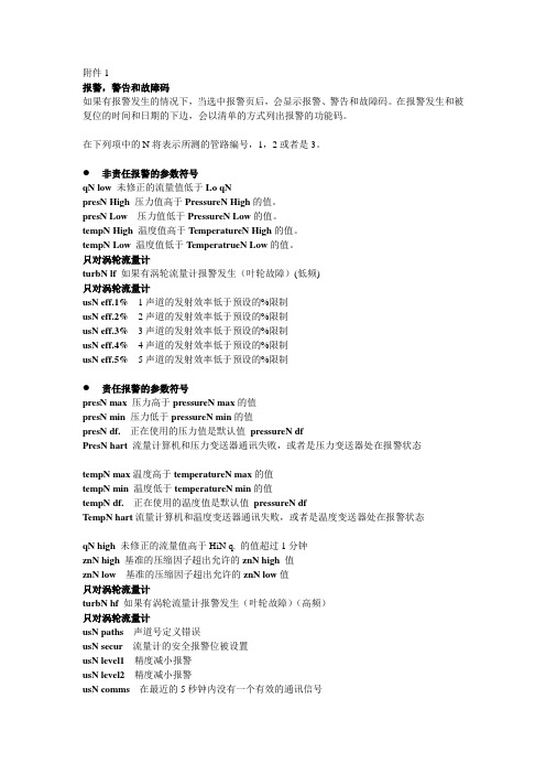
附件1报警,警告和故障码如果有报警发生的情况下,当选中报警页后,会显示报警、警告和故障码。
在报警发生和被复位的时间和日期的下边,会以清单的方式列出报警的功能码。
在下列项中的N将表示所测的管路编号,1,2或者是3。
●非责任报警的参数符号qN low未修正的流量值低于Lo qNpresN High压力值高于PressureN High的值。
presN Low 压力值低于PressureN Low的值。
tempN High 温度值高于T emperatureN High的值。
tempN Low 温度值低于T emperatrueN Low的值。
只对涡轮流量计turbN lf如果有涡轮流量计报警发生(叶轮故障)(低频)只对涡轮流量计usN eff.1% 1声道的发射效率低于预设的%限制usN eff.2% 2声道的发射效率低于预设的%限制usN eff.3% 3声道的发射效率低于预设的%限制usN eff.4% 4声道的发射效率低于预设的%限制usN eff.5% 5声道的发射效率低于预设的%限制●责任报警的参数符号presN max 压力高于pressureN max的值presN min 压力低于pressureN min的值presN df. 正在使用的压力值是默认值pressureN dfPresN hart 流量计算机和压力变送器通讯失败,或者是压力变送器处在报警状态tempN max温度高于temperatureN max的值tempN min 温度低于temperatureN min的值tempN df. 正在使用的温度值是默认值pressureN dfT empN hart流量计算机和温度变送器通讯失败,或者是温度变送器处在报警状态qN high未修正的流量值高于HiN q. 的值超过1分钟znN high基准的压缩因子超出允许的znN high值znN low基准的压缩因子超出允许的znN low值只对涡轮流量计turbN hf如果有涡轮流量计报警发生(叶轮故障)(高频)只对涡轮流量计usN paths 声道号定义错误usN secur流量计的安全报警位被设置usN level1 精度减小报警usN level2 精度减小报警usN comms 在最近的5秒钟内没有一个有效的通讯信号●温度报警tempN alrm温度低于t-alarm的值,并且qb高于Lo.q超过1小时在下列项中的X将表示接、插板槽的编号1,2,3,4或者是5。
- 1、下载文档前请自行甄别文档内容的完整性,平台不提供额外的编辑、内容补充、找答案等附加服务。
- 2、"仅部分预览"的文档,不可在线预览部分如存在完整性等问题,可反馈申请退款(可完整预览的文档不适用该条件!)。
- 3、如文档侵犯您的权益,请联系客服反馈,我们会尽快为您处理(人工客服工作时间:9:00-18:30)。
1.1.4 允许介质
z 只有根据技术信息或用户的使用经验能够确认的介质才可以被测量,并且接触介质的 部件(过程连接、测量管道)对介质的抗化学和物理能力不会在仪表的使用寿命中受 到负面影响。
FM-认证 订单号 完整型号 流量计尺寸 防护等级 环境温度 电源电压和最大功率 过程连接和压力等级 流量计管道材料和标定因子 标定精度 最大流速和TAG-号码
1.1.7 人员资质
z 只有经系统操作员培训并授权的人员才可进行仪表的电气安装、开车以及维护。这些人 员必须阅读、理解并遵守操作手册。
1.1.8 用户责任
2
FCM2000
D184B111U02
1 基本安全信息和使用方法
1 基本安全信息和使用方法
1.1 基本安全信息
1.1.1 仪表安全标准
z 本仪表符合压力设备规范以及最新技术的安全要求。本仪表已根据安全要求通过工厂 测试,并根据正确的订单发货。为使仪表在操作过程中仍符合安全指标,必须遵守本 操作手册中列出的要求。
操作手册
D184B111U02
标准软件 D699G001U01 A.3x
科里奥利质量流量计
FCM2000 可同时测量 质量流量、密度和温度
产品名称 FCM2000
操作手册
零件号. D184B111U02
发行日期: 版 本:
11/04 01
制造商:
ABB Automation Products GmbH Dransfelder Str. 2 37079 Göttingen, Germany
z 在测量腐蚀性或磨损性介质之前,操作员必须评估接触液体部件的抗腐蚀与抗磨损能 力。ABB 原意为其选择的介质提供评估帮助,但不承担任何责任。
z 遵守关于电子设备的安装、功能测试、修理和维护的国家标准。
10
FCM2000
D184B111U02
1 基本安全信息和使用方法
1.1.9 运输中可能的风险
仪表运输到安装地点(尤其是超过50Kg的仪表)过程中注意:
.
安装螺栓 基座
注意!
密封螺栓
不要松开管座上的安装螺栓。不要从管座上移除转换器。这可能会损坏仪表。如果有问题出 现,请联系ABB服务人员。
z 拆除仪表之前确定是否有危险材料存在于流量计中。危险残留物可能仍存在于流量计 中并在打开流量计时逸出。
z 如果管道存在震动,建议确保法兰的螺栓螺母紧固以防松动。 z 在操作者职责范围内,应定期检查仪表,包括:
z 如果用户无法完全清除危险材料,则应在装运时附加相应的文档,声明该情况。在维 修过程中,ABB 公司在维修过程中清除危险材料所产生的费用将由仪表所有者承担。
信息!
本操作手册包含流量计的启动和测试说明以及仪表设计的规格。制造商保留因技术改进引起 的改变硬件和/或软件的权力。更新和可能的扩展信息可以从ABB德国工厂或ABB销售部门得 到。
压力设备制造商名称。
本铭牌包括铭牌a)中的大部分内容,除了以下区 别:
根据PED/DGRL中第3章第3节,压力设备上没有CE标志。 此例外的原因在PED/DGRL中第3章第3节中有描述。 压力设备被分类为SEP(良好的工程实例)。
c) 标准转换器典型铭牌
订单号 完整型号 电源电压 最大功率 流量计尺寸和防护等级 过程连接和压力等级 流量计管道材料 标定因子 标定精度 最大流速 允许的介质温度
z 请注意关于防暴设计的仪表启动的特别信息,在本手册第七章。 z 仪表符合 EN61326/NAMUR NE21 的电磁兼容(EMC)要求及低电压指示。 z 对于尺寸直到 DN100(4”)的科里奥利质量流量计有防水外壳可选项,流量计传感器
的最大工作压力为 PS=40bar(外壳的爆炸压力为 PS>60bar)。在压力设备指示的可用 范围内本保护设计不会失效。 z 当供电中断发生时,仪表参数存储在一个 FRAM(包括最新的累积值)中。当供电恢复 时,仪表可立即工作。
警告!
当外壳盖子被拆除时,EMC和人员保护将失效并存在电击风险。 在打开外壳盖子之前请切断电源。
1.1.12 在Ex-区域使用可能的风险
在Ex-区域,电源、输入输入信号和接地有特殊要求。请注意操作手册中“Ex-保护”一章的 特别说明。
1.1.13 操作中可能的风险
z 磨损性介质和/或气蚀可能引起承压部件的损坏。 z 测量高温介质时,接触流量计表面可能会导致烫伤。 z 侵蚀性介质可能导致腐蚀和/或磨损。加压介质可能从流量计泄漏。
铭牌包括下列规格: CE-标志(认证机构的标志编号),证明仪表(压 力设备)符合PED/DGRL的要求。
b) 压力设备尺寸≤DN25[1”]
制造商提供的用以标识压力设备的序列号。
设备的口径和压力等级。 制造压力设备的材料和垫圈材料(接液)。
制造年份和根据PED(压力设备指示/DGRL)介质组 1=危险液体、气体(包括不稳定气体)的可应用 介质组的规范。
-流量计运行是否正常 -密封性是否良好 -磨损状况(腐蚀、磨损、气蚀)
1.1.15 返回
如果必须将仪表返回ABB工厂进行维修或重新标定,请使用原始包装材料或合适的保护性包 装。请注明返回原因。
信息!EU-危险材料规范
特殊废料的所有者应负责消除污染,且必须在装运之前满足下列要求:
z 所有返回 ABB 自动化产品部维修的流量计传感器以及/或者流量计转换器都不得存在任 何危险材料(酸、碱、溶剂等)。任何孔洞中,例如流量计管道和外壳之间,可能存在 的危险材料都应冲洗干净并中和。证实已执行这些措施的书面证明应和仪表一起返 回。
ABB 授权的工厂实行。扩展作业必须经 ABB 认证。对未经授权的操作我们不承担任何 责任。
必须遵守本操作手册中的操作、服务和维护要求。对于不适当或禁止的使用造成的损 坏,制造商不承担任何责任。
D184B111U02
FCM2000
7
1 基本安全信息和使用方法
1.1.3 规格限制
仪表的使用范围绝不可超出铭牌以及操作手册中规定的限制。下列限制必须遵守:
z 具有未知特性的介质只有在用户执行定期检查以确保流量计的安全系数没有受到影响 的条件下才可进行测量。
1.1.5 安全标志、符号、类型、铭牌以及CE-标志 所有安全、符合以及铭牌和类型铭牌都应保持可读,不得损坏或遗失注意下列陈述:
警告! 小心! 信息! Ex-保护
CE-标志
表示存在风险或者危险的信息,可能导致严重的或者致命的 员伤害。
12
FCM2000
D184B111U02
2 工作原理
2 工作原理
ABB 自动化产品质量流量计的工作是基于科里奥利原理的。FCM2000 的结构采用了经典的平 行测量管道并且在细节上以节约空间和弯曲设计为特点,以有优势的价格给客户提供了宽 广的流量计尺寸范围。 当一定的质量流体流过振动的管道时,会产生使管道弯曲和扭曲的科氏力。这些微小的管 道变形被安装在最佳位置处的传感器检测出来并进行电子评估。由于传感器测得的相位迁 移信号与质量流量成正比,科里奥利质量流量计可以直接测量质量流量。测量原理与流体 的密度、温度、粘度、压力及电导率无关。 测量管道始终以共振的方式振动。在工作条件下,这个共振频率是测量管道几何形状、流 量计材料特性和测量管中流体(也在振动)质量的函数。流量计可以精确地测量被测流体 的密度。 一个集成的温度传感器测量流体的温度,用来校正对易受温度影响的仪表参数。总之,科 里奥利质量流量计可以同时测量质量流量、流体密度和温度。其他测量值可由这些值导 出,例如体积流量或浓度。
1.1.2 使用方法
本仪表用于:
z 传输液体和气体(包括不稳定气体) z 直接测量流体的质量流量 z 测量流体的体积流量(由质量流量和密度间接计算) z 测量流体密度 z 测量流体温度
规定的使用方法包括:
z 在技术指标的限制范围内安装。 z 注意并遵守允许的流体信息。 z 注意并遵守操作手册中的信息。 z 注意并遵守附属文档中的信息(数据表,图标,尺寸图等)。
D184B111U02
FCM2000
11
1 基本安全信息和使用方法
1.1.14 检查和维护中可能的风险
z 检查仪表前确认仪表和相邻管道以及储罐已减压。 z 打开外壳盖子前确认切断电源。
警告!
不要松开管座上的安装螺栓或流量计传感器上 的密封螺栓。带压介质可能会喷出并引起严重 伤害。在打开流量计前应先将管道减压。
禁止对仪表的下列下列使用方法:
z 作为管道中的弹性补偿元件使用,例如用于补偿管道错位,管路震动及管路膨胀等。 z 作为攀爬支撑物,例如安装时。 z 作为外部负载的支撑,例如支撑管路等。 z 去除材料,如在外壳上钻孔,或增加材料,如喷涂(在铭牌上)、焊接等。 z 维修、更改、扩展以及使用备件都只能按照操作手册中的说明进行。除非维修是有
1.1.11 电气安装中可能的风险
z 电子连接只能由有资质的人员根据接线图完成。 z 要遵守操作手册中关于电子连接的信息,否则可能会影响电子保护等级。 z 流量计系统要接地。 z 电源的连接必须要符合相应的国家和国际标准。每个仪表要安装隔离保险丝,保险丝
应 安 装 在 仪 表 附 近 并 明 确 标 识 。 仪 表 的 防 护 等 级 为 IP67 。 过 电 压 种 类 为 Ⅱ (IEC664)。
z 重心可能偏移。 z 仪表可能撞到的障碍物。 z 保护性的运输项目(例如开口处的密封螺栓)。
1.1.10安装中可能的风险
在安装之前确认:
z 流动方向与方向指示一致。 z 仪表安装无应力(平行轴对称配对法兰),使用适合操作条件的垫圈。 z 确保要求的前后直管段长度。 z 流量计前后的管道得到可靠支撑。