AEC-Q200培训教材
CAESARII培训讲义
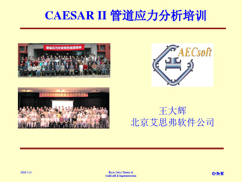
2012-2-17
Basic Stress Theory & CAESAR II Implementation
规范应力” 基本应力 “Code Stress规范应力 规范应力
• Markl’s 试验和结果 将试验用的管道充满水,按某个方向和位移反复摇晃管道。Test configurations filled with water and cycled through a predetermined displacement 预测失效循环次数Theory should be able to predict “cycles to failure” 发现最先失效的管件及其原因Fittings caused early failure … because … 对管件引入应力集中Stresses concentrations are introduced by fittings 分析试验数据,修正轴向应力弯曲项Test data analyzed and a modification to the bending term of the code stress equation was introduced: Sbending = i M / z
2012-2-17
Basic Stress Theory & CAESAR II Implementation
轴向应力
• 沿管道轴向Along axis of pipe • 轴向力引起Axial Force
– 轴向力/面积 (F/A)
• 内压引起Pressure
– Pd / 4t or P*di / ( do2 - di2 )
• • • •
•
2012-2-17
Basic Stress Theory & CAESAR II Implementation
培训教材(初级版)

黄石市科威自控有限公司——EC/EP系列嵌入式PLC培训教材(初级版)序言电控技术日异月新,市场需求日益苛刻。
作为一家“以复兴民族自动化工业为已任”的科技型公司,只是学习、消化、汲取、实践别人的产品和技术是远远不够的,一定有自己独创的产品,才能在没有硝烟的战场上取获成功。
在董事长龚云生同志的得力领导下,公司公司骨干一直朝着“创新是一个民族的灵魂,是国家兴盛发达的不停动力”的方向奋进。
十余年来,战胜了重重困难,坚韧不拔地走自己的路。
发场团队精神,仔细累积和总结经验;自主创新与借“脑袋”并举。
天道酬勤,科威公司的科技成就不停浮现,特别是2005年,EC/EP系列嵌入式PLC在黄石市科威自控有限公司研发成功了!为我国的自动化工业增加了光彩。
自嵌入式PLC的成就在网上公布后,感兴趣的同仁日新月异,渴求认识其技术性能。
正由于嵌入式PLC刚才问世,知者甚少,为此,科威公司决定创办嵌入式PLC培训班。
这是切合“科学发展观”的要求的。
培训班的教材内容,由表及里,由浅入深。
因受时间和要求所限,不系统,重视实践。
希望对初学者,有所补益。
卫工08 年5月一、嵌入式PLC简介1、开发背景工控系统有大系统和小系统,特别是小系统,范围广,几乎覆盖了全部行业,并且要求是千差万其余。
控制器件有DCS、IPC和PLC等。
广大工控设计人员在器件选型时十分疑惑。
在数据办理上要求像IPC,在靠谱性上要求达到或超出PLC,在价位上力求便宜,好像单片机;在二次开发(应用程序)方面要求语言普通化、易学易懂易掌握。
谁都梦想有一款新式的工控产品能代替、包括IPC、PLC和单片机。
经过艰辛的努力,嵌入式PLC在科威公司问世了。
嵌入式PLC已列入国家科技攻关计划项目的阶段成就。
项目代号为2005BA206C。
2、什么是嵌入式PLC?嵌入式PLC是将通用的PLC梯形图语言、CANbus现场总线协议嵌入到单片机中,使其更具个性化、差别化,应用更宽泛、更灵巧,对用户更方便。
Panasonic AEC-Q200 合规性解决方案指南说明书
Capacitors • Electromechanical • Wireless Connectivity • Resistors • Inductors • Relays • Connectors • Storage Media • Sensors • Semiconductors • Circuit Protection • Thermal Management Copyright © 2018 Panasonic Corporation of North America. | All Rights Reserved. | AEC-Q200 Compliance Solutions Guide Rev 5, FY15-081-xxxx
ERJ - U
All Case Sizes except 0201, Ag Pb Based
EXB - U24 / U28 / U2H 2/4/8 Elements Array, 0402 Base
EXB - U34 / U38
2/4 Elements Array, 0603 Base
CHIP RESISTOR ARRAYS
ERJ - 1TR
2512, Low Ohmic Value
CURRENT SENSING CHIP RESISTORS, METAL PLATE TYPE
ERJ - MS
2512, 2526
ERJ - MB
1020
HIGH POWER CURRENT SENSING CHIP RESISTORS
ERJ - A1
EEV - F
105°C, Surface Mount, Low Impedance
cA二级建造师施工项目管理讲义(进度、质量、安全)74页PPT【可修改文字】

2Z100000 建设工程施工管理
2Z103000 施工进度控制 2Z104000 施工质量控制 2Z105000 安全与环境管理
2Z103000 施工进度控制
知识体系: 进度控制(含义、目的和任务) 进度计划(分类、作用、编制) 控制措施(组织、管理、经济、技术) 进度计划编制 横道图计划 网络图计划
2Z103010 进度控制的含义、目的和任务( P109 )
一、含义:在确保进度目标的前提下,在项目进展过程中不断调整进度计划的过程(动态控制)。 论证目标 编制计划 纠偏调整 二、目的:确保进度目标的实现。 三、任务:业主方、设计方、施工方、供货方 业主方:设计准备阶段 设计阶段 施工阶段 物资采购阶段 项目动用前准备阶段。
2Z103012 进度控制的含义、目的和任务(核心知识)
一、动态的进度控制过程包括哪些环节组成? 答:建设项目是在动态条件下实施的,进度控制也就必须是一个动态的管理过程,它由下列环节组成: (1)进度目标的分析和论证; (2)在收集资料和调查研究的基础上编制进度计划; (3)定期跟踪检查所编制进度计划执行情况。 二、代表不同方利益的项目管理的进度控制的目标和时间范畴是否相同? 答:建设工程项目管理有多种类型,代表不同方利益的项目管理(业主方和项目参与各方)都有进度控制的任务,但是,其控制的目标和时间范畴是不相同的。
二级注册建造师
考试辅导讲义之一
2007年二级建造师考试安排
一、二级建造师考试时间:2007年10月26日~27日。 二、二级建造师考试科目、题型、题量、分值: 1、《建设工程施工管理》:单选题70题(70分),多选题25题(50分),满分120分。 2、《建设工程法规及相关知识》:单选题60题(60分),多选题20题(40分),满分100分。 3、《专业工程管理与实务》单选题40题(40分),多选题10题(20分),案例题3题(60分),满分120分。
Coilcraft线艺AEC-Q200认证电感0402CS系列选型手册
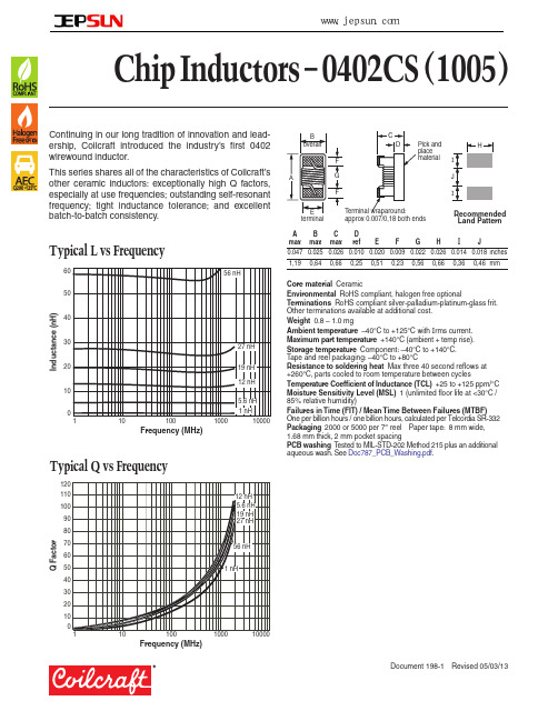
www.jepsun.com
Chip Inductors – 0402CS (1005)
Continuing in our long tradition of innovation and leadership, Coilcraft introduced the industry’s first 0402 wirewound inductor.
90 80 70 60 50 40 30 20 10
0 1
12 nH 5.6 nH 19 nH 27 nH
56 nH
1 nH
10
100
1000
Frequency (MHz)
10000
B overall
F
A
G
F
C
D
Pick and
H
place
material I
J
I
E terminal
Terminal wraparound: approx 0.007/0,18 both ends
1040 1040 1040
960 790 640 840 840
840 700 640 800 760
760 680 680 680 480
680 480 480 640 640
440 560 560 420 480
420 400 400 400 400
400 400 320 200 320
100 150 100 100 100
55
16.6
46
18.3
57
19.1
50
20.7
52
23.2
53
23.8
49
AEC--Q200

AEC-Q200被動(無源)組件應力測試認證規範
說明:
近年來,隨著車載應用設備多功能化的進展,而且在混合動力車以及電動汽車的普及進程中,以電源監視功能為首的新用途也在不斷地擴大,車+125℃、-55℃~+175℃)的高可靠性要求日益高漲,一台汽車是由許許多多的零件組成,這些零件雖然有大小,但是全部都與汽車駕駛的生命安全能達到最高品質與可靠度,甚至要求做到零缺陷的理想境界,所以在汽車產業中,汽車零件的品質控管的重要性往往凌駕於零件的功能性之上,這不一樣的,也就是說對於汽車零件而言,產品的最大通動力往往不是[最新技術],而是[品質安全]。
為了達到對品質要求的提升,就得靠嚴格管控程資格及品質系統標準的就是AEC(汽車電子委員會),針對於主動零件所設計出的標準為[AEC-Q100],針對於被動元件設計為[AEC-Q200],其規範了度。
AEC-Q100車用IC產品驗證流程圖:。
高速数据应用特定电路芯片(AEC-Q200认证)说明书

Product features• AEC-Q200 qualifed• Ultra-low capacitance (0.05 pF) ideal for high speed data applications• Provides Electro static discharge (ESD) protection with fast response time (<1 ns) allowing equipment to pass IEC 61000-4-2 Level 4 test and ISO10605.• Single-line, bi-directional device• Low leakage current (<0.1 nA typ.) reduces power consumption• 0402 (1005 metric) compact design utilizes less board space Applications• I nfotainment and telematics• In-vehicle infotainment (IVI) and navigation • Audio subsytems• USB and Ethernet hubs• Active noise cancellation (ANC)• High speed data ports and interface• RF Antenna• Ethernet• USB• HDMI• Automotive body electronics• Central body control unit• Vehicle access control system• Advanced driver assistance systems• Rear and front view cameras• Automatic parking control• Adaptive cruise control (ACC)• Satellite navigation systemsOrdering• Specify part number and termination suffix (e.g. 0402ESDA-AEC1)0402ESDA-AEC=part number,1=Termination suffixT ermination suffixes• 1 (Dip termination, Packaged:Tape and reel, 10 000 parts per 7” diameter reel)0402ESDA-AEC Automotive grade ESD suppressorPb HALOGENHFFREE2Technical Data 10763Effective September 20200402ESDA-AECAutomotive grade ESD suppressor/electronicsProduct specificationsPart number 4Rated voltage (V dc )maximumClamping voltage 1(V) typicalTrigger voltage 2(V) typicalCapacitance @ 1 MHz (pF)typicalCapacitance @ 1 MHz (pF)maximumAttenuation change (0–6GHz) (dB)typicalLeakage current @12 V dc (nA)typicalESD capability IEC61000-4-2 Direct discharge (kV) typicalESD capability IEC61000-4-2 Air discharge (kV) typicalESD capability ISO10605Direct discharge (kV) typicalESD pulse withstand 1,3typical0402ESDA-AEC 30353000.050.15-0.2<0.112258>10001. Clamping voltage: Per IEC61000-4-2, Level 4 waveform (8 kV direct 30 A) measured 30 ns after initial pulse.2. Trigger voltage: Trigger measurement made using Transmission Line Pulse (TLP) method.Dimensions—mm [in]3. Minor shifting in characteristics may be observed over multiple ESD pulses at very rapid rate.4. Part Number Definition: 0402ESDA-AEC 0402ESDA= Product code and size -AEC= Form designationDesign considerationsThe location in the circuit for the 0402ESDA-AEC has to be carefully determined. For better performance, the device should be placed as close to the signal input as possible and ahead of any other component. Due to the high current associated with an ESD event, it isrecommended to use a “0-stub” pad design (pad directly on the signal/data line and second pad directly on common ground).3Technical Data 10763Effective September 20200402ESDA-AECAutomotive grade ESD suppressor /electronics Environmental dataOperating temperature: - 55 °C to +125 °CStorage temperature (component): - 55 °C to +125 °COperational life: MIL-STD-202, method 108 (1000 hours at +125 °C, bias 85% of rated voltage)Temperature cycling: JESD-22, method JA-104 (-55 °C to +125 °C, 1000 cycles)High temperature exposure: MIL-STD-202, method 108 (1000 hours at +150 °C unpow-ered)Packaging information—mmSupplied in tape-and-reel packaging, 10,000 parts per reel, 7” diameter reel.Mechanical shock: MIL-STD-202, method 213 Mechanical vibration: MIL-STD-202, method 204Biased humidity: MIL-STD-202, method 103 (1000 hours at 85% RH/85 °C, 85% of rated voltage)Endurance test: IEC6100-4-2 standrd ESD pulse: 8 kV contact, 1000 pulses, 1 second intervalSolderability: J-STD-002, method B14Technical Data 10763Effective September 20200402ESDA-AECAutomotive grade ESD suppressor/electronicsT e m p e r a t u r eTimeT T T T Wave solder profileReference EN 61760-1:2006Profile featureStandard SnPb solderLead (Pb) free solderPreheat • Temperature min. (T smin )100 °C 100 °C • Temperature typ. (T styp )120 °C 120 °C • Temperature max. (T smax )130 °C 130 °C • Time (T smin to T smax ) (t s )70 seconds 70 seconds D preheat to max Temperature150 °C max.150 °C max.Peak temperature (T P )*235 °C – 260 °C 250 °C – 260 °C Time at peak temperature (t p )10 seconds max5 seconds max each wave 10 seconds max5 seconds max each wave Ramp-down rate~ 2 K/s min ~3.5 K/s typ ~5 K/s max ~ 2 K/s min ~3.5 K/s typ ~5 K/s max Time 25 °C to 25 °C4 minutes4 minutesManual solder+350 °C (4-5 seconds by soldering iron), generally manual/hand soldering is not recommended.EatonElectronics Division 1000 Eaton Boulevard Cleveland, OH 44122United States/electronics © 2020 EatonAll Rights Reserved Printed in USAPublication No. 10763September 2020Technical Data 10763Effective September 20200402ESDA-AECAutomotive grade ESD suppressor Life Support Policy: Eaton does not authorize the use of any of its products for use in life support devices or systems without the express writtenapproval of an officer of the Company. Life support systems are devices which support or sustain life, and whose failure to perform, when properly used in accordance with instructions for use provided in the labeling, can be reasonably expected to result in significant injury to the user.Eaton reserves the right, without notice, to change design or construction of any products and to discontinue or limit distribution of any products. Eaton also reserves the right to change or update, without notice, any technical information contained in this bulletin.Solder reflow profileT e m p e r a t u r eT LT PEaton is a registered trademark.All other trademarks are property of their respective owners.Follow us on social media to get the latest product and support information.Reference J-STD-020Profile featureStandard SnPb solderLead (Pb) free solderPreheat and soak • Temperature min. (T smin )100 °C 150 °C • Temperature max. (T smax )150 °C 200 °C • Time (T smin to T smax ) (t s )60-120 seconds 60-120 seconds Ramp up rate T L to T p 3 °C/ second max. 3 °C/ second max.Liquidous temperature (T l ) Time (t L ) maintained above T L183 °C60-150 seconds 217 °C60-150 seconds Peak package body temperature (T P )*Table 1Table 2Time (t p )* within 5 °C of the specified classification temperature (T c )20 seconds*30 seconds*Ramp-down rate (T p to T L ) 6 °C/ second max. 6 °C/ second max.Time 25 °C to peak temperature6 minutes max.8 minutes max.* Tolerance for peak profile temperature (T p ) is defined as a supplier minimum and a user maximum.Table 1 - Standard SnPb solder (T c )Package thicknessVolume mm3 <350Volume mm3 ≥350<2.5 mm 235 °C 220 °C ≥2.5 mm220 °C220 °CTable 2 - Lead (Pb) free solder (T c )Package thicknessVolume mm 3 <350Volume mm 3350 - 2000Volume mm 3 >2000<1.6 mm 260 °C 260 °C 260 °C 1.6 – 2.5 mm 260 °C 250 °C 245 °C >2.5 mm250 °C245 °C245 °C。
AEC_Q200-003A
ATTACHMENT 3AEC - Q200 - 003BEAM LOAD (BREAK STRENGTH) TESTMETHOD - 003PASSIVE COMPONENTSURFACE MOUNTED CERAMIC CAPACITORSBEAM LOAD (BREAK STRENGTH) TEST1.0 SCOPE1.1 DESCRIPTION:This specification establishes the procedure and criteria for evaluating break strength.Documents:1.2 ReferenceNot Applicable2.0 EQUIPMENT:Apparatus:2.1 TestThe apparatus required for testing shall be equivalent to the fixture shown in Figure 1.PROCEDURE:3.0 TESTSize:3.1 SampleThe total number of components and lots to be tested are listed in Table 1 of AEC-Q200specification.3.2 Test Environment :Place the part in the beam load fixture. Apply a force until the part breaks or the minimum acceptable force level required in the user specification(s) is attained.3.3 Measurement:Prior to beam load testing, complete the external visual (TST NO. 9) test. Record the force levelat which the part breaks to conclude the test.Breaking strengthTested with the fixture described belowFigure 1: Typical equivalent circuit for Beam Load TestNote: S = .55 ± 0.05 of the nominal length of Device Under Test4.0 FAILURECRITERIADuring (if applicable) and after subjection to test, part rupture prior to any minimum user force requirement shall be considered a failure.Revision HistoryRev # Date of change Brief summary listing affected paragraphsApril 30, 1996 Initial Release.A March 15, 2000 Removed CDF designation through document.Removed Chrysler, Delco, and Ford logo from each heading.Add Component Technical Committee to each heading.。
- 1、下载文档前请自行甄别文档内容的完整性,平台不提供额外的编辑、内容补充、找答案等附加服务。
- 2、"仅部分预览"的文档,不可在线预览部分如存在完整性等问题,可反馈申请退款(可完整预览的文档不适用该条件!)。
- 3、如文档侵犯您的权益,请联系客服反馈,我们会尽快为您处理(人工客服工作时间:9:00-18:30)。
批次 1 1 1
30
1
15
1
15 每种条件
1
30 Note A
1
Present certificate of compliance提供合格证明书
30
1
30
1
30
1
接受标准 0 0 0 0 0 0 0
0 0 0
N:非破坏性测试,器件可用于组装到板子上进行其它测试或者可用于生产;D:破坏性测试,器件不可重新用于认证测试或生产;S:只要求用于表面贴装元件;G:允许通用数据
2 MLCC认证要求及目的
表2-钽和陶瓷电容器参考方法
应力方式
No.
Pre-andPost-
StressElectricalTest
1
应力测试前后电气测试
High Temperature
Exposure
3
(Storage)高温存储
表1-认证测试样品数量要求
应力方式
Pre-and Post-Stress Electrical Test 应力测试前后电气测试
High Temperature Exposure 高温存储
Temperature Cycling 温度循环
NO
注释
1
G
3
DG
4
DG
样品数/批
批次
所有进行认证的产品都应送去测试
铝电解电容器
薄膜电容器,铁氧体,R/R-C网络和可调电容器 /
典型的应用案例 所有的汽车
大部分引擎
乘客仓高热点 多数乘客仓 非汽车类
1.1.2 应用承认:承认被定义为用户同意在他们的应用及任何适用的补充文件和任何适用的用户封装规格中使用某零件 ,但用户承认的方式已经超出了本文件的范围.
2 MLCC认证要求及目的 2.1 AECQ 认证规范的目的是保证MLCC满足表1/表2测试项目的要求。
77 Note B
1
77 Note B
1
接受标准 0 0 0
Destructive Physical Analysis 破坏性物理分析
5
DG
77 Note B
1
0
Moisture Resistance 湿度抵抗
Humidity Bias 偏高湿度
High Temperature Operating Life 高温工作寿命
AEC-Q200认证是什么? AEC-Q200:stress test qualification for passive components--被动元件汽车级品质认证; 汽车电子的过电压保护存在更为严苛的电路条件,因此一般要求制造商通过ISO/TS16949的质量体系认证,相关 的分立器件要求通过AECQ101认证,被动元件要求通过AECQ200认证,是非常严苛的认证规范。一般来说12V的汽 车电子系统使用5-6KW28V的TVS(瞬态抑制二极管),24V的汽车电子系统使用36V的TVS即可。
AEC-Q200与TS的区别? TS16949是管理体系,AEC-Q200是是针对汽车上应用的被动元器件的产品标准。
二、条款简要内容
1.1 描述 AECQ 定义了无源电子器件的低应力测试认证要求和参考测试条件。使用本标准并不是要解除供应商自己内部认证项目的责 任性。在本文中,其中的用户被定义为所有按照规格书使用其认证器件的用户,用户有责任去证实确认所有的认证数据与本 文件相一致。 1.1.1 应力认证测试的定义:应力认证测试定义为成功地完成本标准中定义的测试。每一种无源电子器件要求的低温度范围 (大能力)以及各等级的典型运用案例(指定应用)列于下表: 如果成功完成备注中的器件类型达到的低温度等级的资格认证,那么将允许供应商声称他们的零件通过了该等级或更低等级 的“AEC认证”。对于低于上述低温度的资格鉴定,将仅允许供应商声称他们的零件通过了较低等级的“AEC认证”。
External Visual 外观
Physical Dimensions 尺寸
Resistance to Solvent 溶剂抵抗
6
DG
7
DG
8
DG
9
NG
10
NG
12
DG
77 Note B
1
0
77 Note B
1
0
77 Note B
1
0
所有提交认证的产品
0
30
1
0
5
1
0
N:非破坏性测试,器件可用于组装到板子上进行其它测试或者可用于生产;D:破坏性测试,器件不可重新用于认证测试或生产;S:只要求用于表面贴装元件;G:允许通用数据
等级 0 1 2 3 4
温度范围
最低
最高
-50°C +150°C
-40°C +125°C
-40°C -40°C 0°C
+105°C +85°C +70°C
无源器件类型 最大能力(除非有特别指定和认证) 扁平芯片陶瓷电阻器、X8R陶瓷电容器
网络电容器、电阻器、电感、变压器、热敏电阻,共鸣器、晶 体和变阻器,所有其它的陶瓷和钽电容器
2 MLCC认证要求及目的
表1-认证测试样品数量要求
应力方式
Mechanical Shock 机械冲击 Vibration 振动
Resistance to Solder Heat 抗焊接热
Thermal Shock 热冲击 ESD 静电放电 Solderability 可焊性
Electrical Characterization 电气特性
AEC-Q200简介
一、背景
什么是AEC? AEC 是“Automotive Electronics Council:汽车电子协会”的简称。 克莱斯勒、福特和通用汽车为建立一套通用的零件资质及质量系统标准而设立了汽车电子委员会(AEC),是主要 汽车制造商与美国的主要部件制造商汇聚一起成立的、以车载电子部件的可靠性以及认定标准的规格化为目的 的团体,AEC建立了质量控制的标准。同时,由于符合AEC规范的零部件均可被上述三家车厂同时采用,促进了 零部件制造商交换其产品特性数据的意愿,并推动了汽车零件通用性的实施,为汽车零部件市场的快速成长打 下基础。主要的汽车电子成员有:Autoliv, Continental, Delphi, Johnson Controls 和 Visteon。
Flammability 可燃性
Board Flex 板弯曲
Terminal Strength (SMD) 端子强度(表面贴装元件) Beam Load 射束负载(断裂强度)
NO
注释
13
DG
14
DG
15
DG
16
DG
ห้องสมุดไป่ตู้
17
D
18
D
19
NG
20
D
21
DS
22
DS
23
DG
样品数/批 30 Note B 30 Note B