艾默生氧化锆Oxymitter4000中文说明书
艾默生 使用超声波对碳氢化合物进行过程监控和流量测量 说明书
FLEXIM GmbHBoxberger Str. 412681 BerlinGermany电话: +49 (30) 93 66 76 60传真: +49 (30) 93 66 76 80保留不经事先通知变更的权利。
保留出错的权利。
FLUXUS 是 FLEXIM GmbH 的注册商标。
网址: 电子邮件:***************Copyright (©) FLEXIM GmbH 2023使用超声波对碳氢化合物进行过程监控和流量测量TSFLUXUS_H721V3-0ZH_Leu, 2023-06-12FLUXUS H721技术规格2023-06-12, TSFLUXUS_H721V3-0ZH_Leu2测量变送器技术参数在校准传感器孔径时2用于时间差法和基准条件3在爆炸危险区域以外 (壳盖打开)技术规格FLUXUS H7213TSFLUXUS_H721V3-0ZH_Leu, 2023-06-12在校准传感器孔径时2用于时间差法和基准条件3在爆炸危险区域以外 (壳盖打开)FLUXUS H721技术规格2023-06-12, TSFLUXUS_H721V3-0ZH_Leu4·数字输出功能·频率输出·二进制输出·脉冲输出数量3运行参数5…30 V/< 100 mA频率输出·范围kHz 0…5二进制输出·二进制输出作为警报输出极限值, 流体换向 或 故障脉冲输出·功能主要用于流量累加·脉冲值unit s0.01 (1000)·脉冲宽度ms 0.05…1000输入输入与主设备电隔离数量最多 4, 根据需求·温度输入类型Pt100/Pt1000接口4线范围°C -150…+560分辨率K 0.01精度±0.01 % 的测量值 ±0.03 K ·电流输入精度0.1 % 的测量值 ±10μA 有源输入U int = 24 V, R int = 50 Ω, P int < 0.5 W, 不耐短路·范围mA 0…20无源输入R int = 50 Ω, P int < 0.3 W ·范围mA -20…+20·电压输入范围V 0…1精度0.1 % 的测量值 ±1 mV 内部电阻R int = 1 MΩ·二进制输入端开关信号5…30 V, 1 mA 5…26 V, 1 mA功能·复位测量值·复位累加计数器·暂停累加计数器·请激活高动态流量测量模式FLUXUSH721**-NNN**-*A H721**-NNN**-*SFLUXUSH721**-A2N**-*A H721**-A2N**-*SFLUXUSH721**-F2N**-*A H721**-F2N**-*S1在校准传感器孔径时2用于时间差法和基准条件3在爆炸危险区域以外 (壳盖打开)技术规格 FLUXUS H7215TSFLUXUS_H721V3-0ZH_Leu, 2023-06-12尺寸FLUXUS H721技术规格2023-06-12, TSFLUXUS_H721V3-0ZH_Leu62"管道安装组件存储·不得在室外存储·存储在原始包装中·干燥、防尘地存储·防阳光辐射·保持所有开口封闭·存储温度: -20…+60 °C7TSFLUXUS_H721V3-0ZH_Leu, 2023-06-12电源1端子接口 (AC)接口 (DC)PE 地线地线N(-)中性导线-L(+)相线+传感器传感器电缆 (传感器 *****8*, ****LI*), 延长电缆传感器电缆 (传感器 *****52)测量通道 A 测量通道 B 测量通道 A 测量通道 B 端子接口端子接口传感器端子接口AV 信号BV 信号X_AV X_BVSMB 插头AVS 屏蔽BVS 屏蔽ARS 屏蔽BRS 屏蔽X_AR X_BR SMB 插头AR 信号BR信号输出1, 2端子接口端子接口通信接口P1+…P4+P1-…P4-电流输出, 电压输出, 频率输出, HART (P1)A+信号 +·RS4851·Modbus RTU 1·BACnet MS/TP 1·M-Bus 1·Profibus PA 1·FF H11B-信号 -P5a...P7a P5b (7)数字输出S屏蔽USB类型 BHi-Speed USB 2.0 Device ·服务 (FluxDiag/FluxDiagReader)LANRJ4510/100 Mbps Ethernet·服务 (FluxDiag/FluxDiagReader)·BACnet IP ·Modbus TCP模拟输入端1, 2温度传感器无源传感器有源传感器端子直接连接通过延长电缆链接接口接口T1a…T4a 红色红色未分配未分配T1A…T4A 红色/蓝色灰色-+T1b…T4b 白色/蓝色蓝色+未分配T1B…T4B 白色白色未分配-S1, S3屏蔽屏蔽未分配未分配开关量输入1, 2端子P1+…P2+, P1-…P2-1电缆 (由客户提供):- 比如 柔性电缆, 带绝缘层, 截面积: 0.25…2.5 mm 2- 电缆外径 (*72***-*****-*S 带铁氧体螺母): 最大 7.6 mm 2数量、型号和端子分配为订单专用。
氧化锆中文说明书
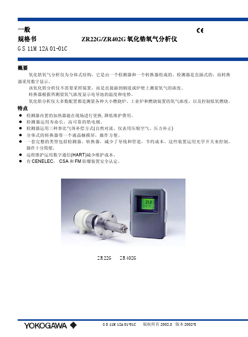
一般规格书ZR22G/ZR402G氧化锆氧气分析仪GS 11M12A01-01C概要氧化锆氧气分析仪为分体式结构,它是由一个检测器和一个转换器组成的。
检测器是直插式的,而转换器采用数字显示。
该氧化锆分析仪不需要采样装置,而是直接插到烟道或炉壁上测量氧气的浓度。
转换器根据所测量氧气浓度显示电导池的温度和电势。
氧化锆分析仪大多数配置都是测量各种大小燃烧炉、工业炉和燃烧装置的氧气浓度,以及控制低氧燃烧。
特点z检测器内置的加热器能在现场进行更换, 降低维护费用。
z检测器运用寿命长,高可靠的锆电极。
z检测器运用三种参比气体补偿方式(自然对流、仪表用压缩空气、压力补正)z分体式的转换器带一个液晶触摸屏,操作方便。
z一套完整的类型包括检测器、转换器,减少了导线和管道,节约成本。
这些装置运用光学开关来控制,操作十分简便。
z远程维护运用数字通信(HART)减少维护成本。
z有CENELEC, CSA和FM防爆装置安全认定。
ZR22G ZR402G芯屏蔽电缆加热器芯屏蔽电缆接点输出HART0~1400常用检测器应用SUS310S 800室。
700~1400℃(带高温探头适配器) 对高温采样气体,应用0.15m长的探头和高温探头适配器ZO21P-H。
采样气体压力:-5~+250kPa(当炉内压力超过3kPa,它用来压力补正; 当炉内压力超过5kPa,必须补偿压力)。
对0.15 m探头来说为0.5~5kPa。
在炉内不能有压力浮动。
探头长度: 0.15,0.4,0.7,1.0,1.5,2.0, 3.0,3.6,4.2,4.8,5.4m探头材料: SUS 316(JIS)环境温度:-20~+150 ℃涉及气体方式:自然对流,仪表用压缩空气,压力补正(其余的探头超过0.15m)仪表用压缩空气方式(包括自然对流除外):压力; 200 kPa+炉内压力(要求用通过露点-20℃以下的冷却干燥空气,且要没有灰尘和油垢。
)消耗量:大约1NL/min气体连接材料:SUS 316(JIS),氧化锆,SUS304(JIS)(法兰), 镍基合金B(Inconel 600,601)结构:加热器和热电偶可更换结构;非防爆产品;相当于国际电气制造业协会 4X/IP 66(只适用于经压力补正的熔炉进行再循环)端子盒材料:铝合金端子盒颜色:外壳:白色(Munsell 0.6GY3.1/2.0)盖子:墨绿(Munsell 2.5GY8.4/1.2)底部:聚亚安酯防腐材料气体连接:Rc1/4或1/4FNPT配线连接:G1/2,Pg13.5,M20×1.5mm,1/2NPT安装:法兰安装探头安装角度:当探头插入长度为2m以下时,安装角度可能为水平到垂直;当探头插入长度为2.5m以内时,安装角度可能为垂直(±5o),如果安装为水平到垂直,要一个保护套管:当探头插入长度为2.5m以上时,为垂直安装(±5o),要一个保护套管。
ES艾默生说明书

UNIDRIVE ES 电梯专用变频器用户手册E1-20030818-C-1.0 (BOM:31010957)E m e r s o n I n d u s t i a l A u t o m a t i o n一般信息因用户疏忽或不当安装或不当调节设备操作参数,或将变频器与不适配的电机搭配使用所导致的任何后果,厂家概不负责。
本手册中的内容,在付印时我们已确认是正确的。
但我公司致力于持续改进产品,因此厂家保留修改该产品规格、性能及本手册其它内容的权力,并不另通知用户。
厂家保留所有权力。
本手册的任何内容,未经厂家书面同意,不得以任何形式复制(包括:影印、记录于存储器或可调用系统)和传播。
变频器软件版本本产品所附带的软件为最新版本。
如果将本产品和其它变频器一起用于新的或现存的系统,由于各变频器软件版本可能不同,将导致本产品功能上的差异。
从本公司用服部门退回的变频器也会有以上问题。
欲知软件版本,可查看Pr11.29(或Pr0.50)及Pr11.34。
软件版本为zz.yy.xx,Pr11.29显示zz.yy,Pr11.34显示xx。
例如:软件版本01.01.00,Pr11.29显示01.01,Pr11.34显示0。
如有疑问,请咨询我公司。
环境声明我公司致力于降低工厂及产品(在整个生命周期内)对环境的影响。
为此,我公司应用了“环境管理系统(EMS)”(Environmental Management System),该系统通过ISO14001认证。
关于EMS的详细信息、我公司的环保政策或其它,请与我们联系,或访问.我公司生产的变频器在长期使用中,可以节能、减少原材料的消耗及浪费。
该产品的上述优点远远抵消了它生产过程中及报废时对环境的影响。
当产品到达服务年限后,可将其方便的拆卸成几大部件,便于循环利用。
该产品大部分部件都是卡入式安装,拆卸时不需使用工具,其它部分用螺钉紧固,方便拆卸。
实际上,各部分零件皆可循环利用。
VERSAFOAMER 4000 用户手册说明书

Foaming:Tank In CaseUse the 7-ft.hose to treat drains,wall voids,and other spaceswith foam.Foaming:Tank RemovedFully pressurize tank,then disconnect tank from compressor hose and remove tank from case;apply foam in short bursts to floor drains and othersites.Operating Instructions4000USER’S MANUALDrill 9/16“hole through concrete;insert straight tip (use stopper to prevent leaking)and apply foam to void;5min.of foaming delivers about 1gal.liquid into soil the hole.Drill 3/16“hole between wall studs,6inches above base-boardInsert curved tip and rotate in an arc to deliver 7one-second bursts (3.5oz.)of foam totreat studs and sillplatebelow.Void-Space ApplicationOperationMixing and Filling•To ensure adequate air pressure in tank,add 3/4to 1gal.liquid to tank.•Make sure switch on compressor is in the Off position,and unit is unplugged from wall connection.•When mixing insecticides in the tank,use the gallon and liter marks on the side.•Mix all insecticides according to label directions.N OTE :Foaming agent must be added to tank to make foam.Pressurizing the Tank•Connect unit to 110V or 220V outlet with 3terminal electric cord.•Start compressor by depressing the on/off switch.•Compressor maintains pressure in the tank,it will automati-cally cycle on and off during normal use,but will not over-pressurize.Safety Precautions95138414Rev 10/09Before Starting•Secure all quick-connect hose connections.•Engage lock on valve.•Tighten tank cap until snug.•Do not connect this unit to external air or gas source;use only with supplied compressor.•Do not pressurize an empty tank.•Open tank cap slowly to release air before removing.•Do not transport the unit while tank is pressurized.•Do not treat voids with electrical outlets or cables.•Always use a grounded (3terminal)extension cord.Sub-Slab Application#Order #Description116200007Compressor,110V 16200020Compressor,220V 216200002Quick-connect 32206731230-L Gunjet valve 422030220Hose,8ft.522026500Gauge,pressure 616200013Curved tip 716200018Straight tip816200023Drain application tipVERSAFOAMER 4000•Flush tank,Gunjet valve,and hose with clean water regularly.•Inspect hoses and hose connections for wear.•Protect application tip when not in use.•Store hose and valve in carry case when not in use.B&G Help Line800-544-8811Problem:Tank not maintaining air pressure Solution:•Tighten tank cap•Check for gasket in tank cap,replace if missing Problem:Tank not getting air pressureSolution:•Inspect/engage hose on compressor and quickconnection Problem:Applying only air not foamSolution:•Tank empty,add liquid insecticide•Siphon tube for foam port is plugged or damaged Problem:Foam not thick or like waterSolution:•Increase amount of foaming agent in tank•Clean inside of hose from tank to 30-L Gunjet valve Problem:Foam delivery is unevenSolution:Clean screen filter behind mozzle in the 30-LGunjet valve Problem:Hose leaks at junction with tankSolution:•Replace Teflon washer,do not over-tightenwasher wheninstalling8125643135REGION SOUTH DRIVE •JACKSON,GA 30233Toll Free 800-544-8811•Phone 678-688-5601 •Fax 678-688-5633。
Oxymitter 4000氧化锆氧量分析变送器中文版

1 Oxymitter 4000氧化锆氧量分析变送器检修1.1 Oxymitter 4000氧化锆氧量分析变送器检修规程1.1.1 设备组成及技术规范1.1.1.1设备原理结构氧化锆工作原理:通过加热的电化学反应池所产生的电压值来表征被测气体的百分比氧浓度。
电化学反应池(氧化锆锆池)是一稳定的、盘状的氧化锆结晶体(氧化钇-氧化锆),多孔金属电极焙烧在锆池两侧。
根据能斯特方程,在高温时( 704℃),锆池的输出电压为:EMF = KT log10(P1/P2) + C其中: P2 表示氧化锆锆池与被测气体接触一侧的氧分压;P1 表示氧化锆锆池与参比空气接触一侧的氧分压;T 代表绝对热力学温度;C 代表锆池常数;K 代表电化学算法校正系数;注意:为了获得最好的分析结果,请采用仪表风(氧含量为20.95%)作为参比空气。
在分析操作温度(704℃),不同浓度的氧进入锆池两侧,由于锆池两侧氧分压不同,锆池中的阳离子将从高浓度的一侧移向低浓度的一侧,锆池两侧形成一电势。
氧浓度每变化十个单位,则输出电压改变50毫伏左右,呈对数关系,即输出电压与氧浓度对数的倒数成正比,因此,当样品气中的氧浓度下降时,输出电压值增加。
这种特性使Oxymitter 4000氧化锆氧量分析变送器在低浓度氧含量测量应用时,具有较高的测量灵敏度。
Oxymitter 4000氧化锆氧量分析变送器由电子变送单元和自动标定序列发生器组成。
Oxymitter 4000氧化锆氧量分析变送器1.1.1.2技术规范1.1.1.2.1 氧浓度范围标准:0-10% O2; 0-25% O2;0-40% O2;1.1.1.2.2 精确度:±0.75%;1.1.1.2.3 仪器对标气的响应时间:最初响应时间小于3秒;T90小于8秒;1.1.1.2.4 锆头工作温度范围:32~1300°F( 0-704℃),带高温选择项,可以到2400°F (1300℃);1.1.1.2.5 电器部分温度范围:-40 to 185°F (-40 to 85℃);1.1.1.2.6 材质:锆头与过程气体接触的部分为316L不锈钢;其它部分为304不锈钢和低铜铝;电子单元为低铜铝;1.1.1.2.7 标定:半自动标定或自动标定;1.1.1.2.8 推荐的标定气体:0.4% O2,背景气为氮气;8% O2,背景气为氮气;1.1.1.2.9 标气流量:5标准立方英尺/小时(2.5 升/分钟);1.1.1.2.10 电源电压:通用电源90-250VAC,48-62Hz,无需切换开关或跨接片。
GEM-Premier-4000标准操作程序(SOP)

血文件名称:GEM Premier4000气分析仪作业指导书版本号:B编制人:罗光成页码:起始第1页共18页颁布日期:2014年07月01日仪器信息文件编号:LAB-BL-SOP-INSTR004修订号:0审核人:蒋兴亮批准人:生效日期:2014年07月01日仪器名称:仪器型号:生产商:生产地:生产日期:产品序号:许可证号:资产权属:参考资料:GEM Premier4000全自动血气分析仪GEM Premier4000Instrumentation Laboratory Co.180hartwell r o ad bedford,MA01730-2443USA 2013年9月12115949/13046291国食药监械(进)字2009第2402580号国食药监械(进)字2009第2402581号川北医学院附属医院GEM Premier4000OPERA TOR’S GU IDEGEM Premier4000CONFIGURATION GUIDE GEM Premier4000DAT A MANAGEMENT GUIDE维修电话:相关记录:检验科生化室G EM Premier4000全自动生化分析仪使用记录检验科生化室G EM Premier4000全自动生化分析仪校准记录检验科生化室G EM Premier4000全自动生化分析仪试剂更换记录检验科生化室G EM Premier4000全自动生化分析仪维护保养与故障记录目录目录 (2)GEM Premier4000全自动血气分析仪 (3)1.应用范围及仪器简介: (3)2.测定范围及方法原理 (4)3.开机 (7)4.关机 (7)5.参数设置: (8)6.试剂装载程序 (10)7.校准和质量控制 (11)8.标本测定程序 (12)9.维护保养程序 (14)10.错误标记(报警信息) (14)GEM Premier4000全自动血气分析仪1.应用范围及仪器简介GEM Premier4000血气分析仪是一台轻便、快捷、准确的血气分析系统,用于迅速定量检测全血样品中的pH、pCO2、pO2、Na+、K+、Cl–、Ca++、血糖、血乳酸、红细胞压积、总血红蛋白、氧合血红蛋白、碳氧血红蛋白、高铁血红蛋白和还原血红蛋白等项目。
Omega CN4000系列温度控制器用户指南说明书

e-mail:**************For latest product manuals: CN4000 SERIESTemperature ControllersShop online at User’s G ui d e***********************Servicing North America:U.S.A. Omega Engineering, Inc.Headquarters: Toll-Free: 1-800-826-6342 (USA & Canada only)Customer Service: 1-800-622-2378 (USA & Canada only)Engineering Service: 1-800-872-9436 (USA & Canada only)Tel: (203) 359-1660 Fax: (203) 359-7700e-mail:**************For Other Locations Visit /worldwideThe information contained in this document is believed to be correct, but OMEGA accepts no liability for any errors it contains, and reserves the right to alter specifications without notice.CONTENTSMODEL CONFIGURATION (2)SPECIFICATIONS (3)PARAMETER AND SETTING (4)SYMBOL DESCRIPTIONS (7)INSTRUMENT INSTALLATION AND WIRING (8)DISPLAY AND OPERATIONS (9)OPERATION DESCRIPTION (10)MODEL CONFIGURATIONModel DescriptionCN4116 (*)-(**)-(***) 1/16 DIN controllerCN4216 (*)-(**)-(***) 1/16 DIN controller, with 0.0 decimalCN414 (*)-(**)-(***) 1/4 DIN controllerCN424 (*)-(**)-(***) 1/4 DIN controller, with 0.0 decimalCN418V (*)-(**)-(***) 1/8 DIN Vertical controllerCN428V (*)-(**)-(***) 1/8 DIN Vertical controller, with 0.0 decimalCN418H (*)-(**)-(***) 1/8 DIN Horizontal controllerCN428H (*)-(**)-(***) 1/8 DIN Horizontal controller, with 0.0 decimal*Specify controlling output code from Output Options table below**Specify alarm code from Alarm Options table below***Low voltage power supply option (-LV)Controlling Output OptionsOption Type CodeRelay -R1DC SSR driver -DC1Alarming Output OptionsOption Type CodeRelay -R2DC SSR driver -DC2Low voltage power supply optionHz50/60AC/DC,-LV 24VSPECIFICATIONSThermocouple RTD Input TypeK S R E J N PT100Range ℃/ ℉0 to1300 ℃32 to 2372 ℉0 to1700℃32 to 3092 ℉0 to1600℃32 to 2412 ℉0 to1000℃32 to 1832 ℉0 to1200℃32 to 2192 ℉0 to 1300℃32 to 2372 ℉-200 to 800℃-328 to 1472 ℉Accuracy:CN 4116/CN414/CN4180.3%FS ± 1℃/1.8°FCN4216/CN424/CN428 0.3%FS ± 0.1℃/0.18°FTemperature Display ResolutionCN 4116/CN414/CN4181℃/1℉CN4216/CN424/CN4280.1℃/0.1℉ON / OFF ControlControl MethodAI PID Control with Auto Tuning (AT)Relay Output (1A/250VAC)Output TypeVoltage Output for SSR(12V/30mA)Limit High / LowAlarm(Modularization) High deviation/Low deviation100~240VAC (-15%, +10%), or 24VDC Supply Voltage50 to 60HzPower Consumption ≦ 3WOperating EnvironmentsTemperature: -10 to +60℃ / 14 to 140℉Humidity: 0~90RH%Electromagnetic compatibility (EMC) IEC61000-4-4: ± 4KV/5KHz IEC61000-4-5: 4KVPARAMETER AND SETTINGField parameter table (Primary parameters)Code Description Remarks SettingRange DefaultHIAL High limit alarm Alarm on when PV>HIALalarm off when PV<HIAL- AHYS-999~+3000 3000LoAL Low limit alarm Alarm on when PV<LoAL;alarm off when PV>LoAL + AHYS-999~+3000 -999HdAL Deviation highalarmAlarm on when PV-SV>HdAL;alarm off when PV-SV<HdAL - AHYS-999~+3000 3000LdAL Deviation lowalarmAlarm on when PV-SV<LdAL;alarm off when PV-SV>LdAL + AHYS-999~+3000 -999Loc Parameter LockLocAutoTuningSVPrimaryParameterSecondaryParameter0 X1 X X2 X X X3 X X X X808: allow to modify data or execute ATX : not allow to modify data or execute AT0~255 0System parameter table (Secondary parameters)Scb Input Shift Parameter Scb is used to make input shift tocompensate the error produced by sensor or inputsignal itself.PV-after-compensation=PV-before-compensation + Scb.-199~+400FILt PV input filter The value of FILt will determine the ability offiltering noise.When a large value is set, the measurement inputis stabilized but the response speed is slow.Generally, if great interference exists, then youcan increase parameter “FILt” gradually to makemomentary fluctuation of measured value lessthan 2 to 5.When the meter of the instrument is beingexamined at laboratory, “FILt” should be set to 0or 1 to short the response time.0~40 1Fru Selection of powerfrequency andtemperature scale50C: 50Hz, ℃50F: 50Hz, ℉60C: 60Hz, ℃60F: 60Hz, ℉50C, 50F,60C, 60F50CSPL Low limit of SV -999~3000SPH Upper limit of SV -999~3000400SYMBOL DESCRIPTIONS Symbol DescriptionorAL Input specification setting is incorrectOrInput wiring is disconnected/ thermocouple problem OrShort circuitedHIAL High limit alarm LoAL Low limit alarm HdAL Deviation high alarm LdAL Deviation low alarm EErr IC Software error 8888 IC Software errorINSTRUMENT INSTALLATION AND WIRINGWiring graph for instruments with dimension 1/4 DIN; 1/8 DIN Vertical and HorizontalNote: The compensation wires for different kinds of thermocouple are different, and should be directly connect to the terminals. Connecting the common wire between the compensation wire and the t e r m i n a l s w i l l c a u s e m e a s u r e m e n t e r r o r.Wiring graph for 1/16 DIN dimension instruments :DISPLAY AND OPERATIONS①Upper display window, displays PV,parameter code, etc.②Lower display window, displays SV,parameter value, or alarm③Setup key, for accessing parametertable and conforming parametermodification.④Data shift key, and auto tuning.⑤Data decrease key⑥Data increase key⑦LED indicator. MAN, PRG, MIO,COM, OP2, AL2, AU1 and AU2Com indicators is non-applicable.OP1 and AL1 will indicate I/O operation of the corresponding module.Basic display status:When power on, the upper display window of the instrument shows the process value (PV), and the lower window shows the set-point (SV). This status is called basic display status.When the input signal is out of the measurable range (for example, the thermocouple or RTD circuit is break, or input specification sets wrong), the upper display window will alternately display “orAL” and the high limit or the low limit of PV, and the instrument will automatically stop output. If the lower display window alternately display “HIAL”, “LoAL”, “HdAL” or “LdAL”, it means high limit alarm, low limit alarm, deviation high alarm, and deviation low alarm happening.OPERATION DESCRIPTIONz Set Value Setting:In basal display status, if the parameter lock “Loc” isn't locked, we can set setpoint (SV) by pressing 、 or . Press key to decrease the value, key to increase the value, and key to move to the digit expected to modify. Keep pressing or , the speed of decreasing or inscreasingvalue get quick. The range of setpoint is between the parameter SPL and SPH.The default range is 0~400.z Parameter Setting:In basal display status, press and hold for about 2 seconds can accessField Parameter Table. Pressing can go to the next parameter; pressing 、 or can modify a parameter. Press and hold can return tothe preceding parameter. Press (don't release) and then press key simultaneously can escape from the parameter table. The instrument will escape auomatically from the parameter table if no key is pressed within 30 seconds. Setting Loc=808 and then press can access System Parameter Table.●AI artificial intelligence control and auto tuningWhen AI artificial intelligence control method is chosen (CtrL=APId), the PID parameters can be obtained by running auto-tuning. In basal display status,press for 2 seconds, the “At” parameter will appear. Press to changethe value of At from “oFF” to “on”, then press to active the auto-tuning process. During auto tuning, the instrument executes on-off control. After 2-3 times of on-off action, the instrument will obtain the optimal control parametervalue. If you want to escape from auto tuning status, press and hold thekey for about 2 seconds until the "At" parameter appear again. Change “At”from “on” to “oFF”, press to confirm, then the auto tuning process will be cancelled.Note 1: If the setpoint is different, the parameters obtained from auto-tuning are possible different. So you’d better set setpoint to an often-used value ormiddle value first, and then start auto-tuning. For the ovens with goodheat preservation, the setpoint can be set at the highest applicabletemperature. Depending on the system, the auto-tuning time can befrom several seconds to several hours.Note 2: Parameter Ctl (on-off differential, control hysteresis) has influence on the accuracy of auto-tuning. Generally, the smaller the value of Ctl, thehigher the precision of auto tuning. But Ctl parameter value should belarge enough to prevent the instrument from error action around setpointdue to the oscillation of input. Ctl is recommended to be 2.0.Note 3: The instrument has the function of self-learning. It is able to learn the process while working. The control effect at the first run after auto tuningis probably not perfect, but excellent control result will be obtained after aperiod of time because of self-learning.10OMEGA’s policy is to make running changes, not model changes, whenever an improvement is possible. T his affords our customers the latest in technology and engineering.OMEGA is a trademark of OMEGA ENGINEERING, INC.© Copyright 2018 OMEGA ENGINEERING, INC. All rights reserved. T his document may not be copied, photocopied, reproduced, translated, or reduced to any electronic medium or machine-readable form, in whole or in part, without the prior written consent of OMEGA ENGINEERING, INC.FOR WARRANTY RETURNS, please have the following information available BEFORE contacting OMEGA:1. P urchase Order number under which the product was PURCHASED,2. M odel and serial number of the product under warranty, and3. Repair instructions and/or specific problems relative to the product.FOR NON-WARRANTY REPAIRS, consult OMEGA for current repair charges. Have the following information available BEFORE contacting OMEGA:1. Purchase Order number to cover the COST of the repair,2. Model and serial number of the product, and 3. Repair instructions and/or specific problems relative to the product.RETURN REQUESTS/INQUIRIESDirect all warranty and repair requests/inquiries to the OMEGA Customer Service Department. BEFORE RET URNING ANY PRODUCT (S) T O OMEGA, PURCHASER MUST OBT AIN AN AUT HORIZED RET URN (AR) NUMBER FROM OMEGA’S CUST OMER SERVICE DEPART MENT (IN ORDER T O AVOID PROCESSING DELAYS). The assigned AR number should then be marked on the outside of the return package and on any correspondence.T he purchaser is responsible for shipping charges, freight, insurance and proper packaging to preventbreakage in transit.WARRANTY/DISCLAIMEROMEGA ENGINEERING, INC. warrants this unit to be free of defects in materials and workmanship for a period of 25 months from date of purchase. OMEGA’s WARRANTY adds an additional one (1) month grace period to the normal two (2) year product warranty to cover handling and shipping time. This ensures that OMEGA’s customers receive maximum coverage on each product.If the unit malfunctions, it must be returned to the factory for evaluation. OMEGA’s Customer Service Department will issue an Authorized Return (AR) number immediately upon phone or written request. Upon examination by OMEGA, if the unit is found to be defective, it will be repaired or replaced at no charge. OMEGA’s WARRANT Y does not apply to defects resulting from any action of the purchaser, including but not limited to mishandling, improper interfacing, operation outside of design limits, improper repair, or unauthorized modification. T his WARRANT Y is VOID if the unit shows evidence of having been tampered with or shows evidence of having been damaged as a result of excessive corrosion; or current, heat, moisture or vibration; improper specification; misapplication; misuse or other operating conditions outside of OMEGA’s control. Components in which wear is not warranted, include but are not limited to contact points, fuses, and triacs.OMEGA is pleased to offer suggestions on the use of its various products. However, OMEGA neither assumes responsibility for any omissions or errors nor assumes liability for any damages that result from the use of its products in accordance with information provided by OMEGA, either verbal or written. OMEGA warrants only that the parts manufactured by the company will be as specified and free of defects. OMEGA MAKES NO OTHER WARRANTIES OR REPRESENTATIONS OF ANY KIND WHATSOEVER, EXPRESSED OR IMPLIED, EXCEPT THAT OF TITLE, AND ALL IMPLIED W ARRANTIES INCLUDING ANY W ARRANTY OF MERCHANTABILITY AND FITNESS FOR A PARTICULAR PURPOSE ARE HEREBY DISCLAIMED. LIMITATION OF LIABILITY: The remedies of purchaser set forth herein are exclusive, and the total liability of OMEGA with respect to this order, whether based on contract, warranty, negligence, indemnification, strict liability or otherwise, shall not exceed the purchase price of the component upon which liability is based. In no event shall OMEGA be liable for consequential, incidental or special damages.CONDITIONS: Equipment sold by OMEGA is not intended to be used, nor shall it be used: (1) as a “Basic Component” under 10 CFR 21 (NRC), used in or with any nuclear installation or activity; or (2) in medical applications or used on humans. Should any Product(s) be used in or with any nuclear installation or activity, medical application, used on humans, or misused in any way, OMEGA assumes no responsibility as set forth in our basic WARRANT Y /DISCLAIMER language, and, additionally, purchaser will indemnify OMEGA and hold OMEGA harmless from any liability or damage whatsoever arising out of the use of theProduct(s) in such a manner.Where Do I Find Everything I Need forProcess Measurement and Control?OMEGA…Of Course!Shop online at TEMPERATUREM U Thermocouple, RTD & Thermistor Probes, Connectors,Panels & AssembliesM U Wire: Thermocouple, RTD & ThermistorM U Calibrators & Ice Point ReferencesM U Recorders, Controllers & Process MonitorsM U Infrared PyrometersPRESSURE, STRAIN AND FORCEM U Transducers & Strain GagesM U Load Cells & Pressure GagesM U Displacement TransducersM U Instrumentation & AccessoriesFLOW/LEVELM U Rotameters, Gas Mass Flowmeters & Flow ComputersM U Air Velocity IndicatorsM U Turbine/Paddlewheel SystemsM U Totalizers & Batch ControllerspH/CONDUCTIVITYM U pH Electrodes, Testers & AccessoriesM U Benchtop/Laboratory MetersM U Controllers, Calibrators, Simulators & PumpsM U Industrial pH & Conductivity EquipmentDATA ACQUISITIONM U Communications-Based Acquisition SystemsM U Data Logging SystemsM U Wireless Sensors, Transmitters, & ReceiversM U Signal ConditionersM U Data Acquisition SoftwareHEATERSM U Heating CableM U Cartridge & Strip HeatersM U Immersion & Band HeatersM U Flexible HeatersM U Laboratory HeatersENVIRONMENTALMONITORING AND CONTROLM U Metering & Control InstrumentationM U RefractometersM U Pumps & TubingM U Air, Soil & Water MonitorsM U Industrial Water & Wastewater TreatmentM U pH, Conductivity & Dissolved Oxygen InstrumentsM4545/0418。
OXYMITTER 4000 氧传感器

OXYMITTER 4000 氧传感器1.系统概论a.范畴通过此说明,我们可以了解安装、启动、操作和维护OXYMITTER 4000的相关知识。
通过积分信号输出4-20mA信号以代表一个氧的测定值。
并提供一键盘模板用于启动、校准和诊断。
b.系统描述OXYMITTER 4000氧传感器设计用于测量工业过程中的氧份浓度;例如,燃料氧化后的氧份的残留量。
该探头被固定安装于烟道内部,无需使用采样系统,直接完成测定。
设备通过研制出的经过加热的电化学孔读取电压值以测得氧份含量。
该孔由氧化钇和氧化锆圆盘组成。
圆盘两侧覆盖有有气孔的金属电极。
在合适的温度操作时,该孔的毫伏电压输出通过下列Nernst等式得出:EMF=KT log10(P1/P2) + C说明:(1)P2为该孔同一边的参考气内的氧部分的压力(2)P1为该孔对面的参考气内的氧部分的压力(3)T为绝对温度(4)C为该孔常数(5)K为一数学常数注意:为了得到最好的测定结果,应使用清洁、干燥的设备用气(20.95%氧份)作为参考气体。
当该孔处于操作温度,且穿过该孔有不等的氧份浓度时,氧离子将从孔的氧高分压边向低分压边移动。
对数输出电压结果在50mv/10。
由于输出值的大小与样品中氧部分的压力的倒数的对数成比例,因此,随着样品气体中氧份浓度的降低,输出信号增加。
这一特点,能使氧分析仪在低氧份浓度时提供期望的灵敏度。
氧传感器在所有可燃烧产品存在下,包括水蒸气,测定氧份含量。
因此,应当考虑到,有可能在比较潮湿的条件下进行分析。
同老的方法比较,例如可对较干燥气体进行分析的便携装置,如要对较潮湿的气体进行分析时,氧份含量测定的百分比较低。
其差异与样品气中水分的多少成比例。
c.系统结构传感器有五种长度选择,使用者可灵活挑选适合烟道尺寸的传感器。
长度选项为: 457mm,0.91m,1.83m,2.7m,3.66m。
积分电子装置控制探头温度,且提供一项绝缘输出,4-20mA,其值与测量的氧份浓度成比例。
- 1、下载文档前请自行甄别文档内容的完整性,平台不提供额外的编辑、内容补充、找答案等附加服务。
- 2、"仅部分预览"的文档,不可在线预览部分如存在完整性等问题,可反馈申请退款(可完整预览的文档不适用该条件!)。
- 3、如文档侵犯您的权益,请联系客服反馈,我们会尽快为您处理(人工客服工作时间:9:00-18:30)。
模拟输出/HART :隔离的 4-20mA 电流输出,最大负载为 950 欧姆,带 HART 通讯功能。 若需要现场总线功能(FieldBus),选择 Oxymitter5000。 2 个逻辑信号输出:可以组态成报警输出,也可以组态成双向标定握手信号,后者提供给标定程序发生器。该逻辑 信号继电器由仪器自供电源(+5V),串联 340 欧姆电阻。 进线孔 3/4″-14 NPT(用于模拟信号和逻辑信号输出)。 电 源 功 耗 注: (1) 所有静态特性参数是指仪器的各种操作变量为常量。 费希尔-罗斯蒙特公司产品满足欧洲的所有技术要求。 Oxymitter4000 的氧化锆锆头,其防护等级为 NEMA 4X,IP65。 :锆头加热器功耗最大额定值为 175 瓦;电子单元功耗最大额定值为 10 瓦
相 对 湿 度
推荐的标定气体 :0.4% O2,背景气为氮气;8% O2,背景气为氮气(参见标气工具 #6296A27G01) 标 气 流 量 :5 标准立方英尺/小时(2.5 升/分钟)
参比气流量(选择项):清洁干燥的仪表风(20.95% O2),压力 5psi(34KPa),流量 2 标准立方英尺/小时 (2.5 升/分钟) 电 子 单 元 电 气 噪 音 :NEMA 4X,IP66,在参比气排放口有接头和短管,其将干净的参比气直排大气 :满足 EN50082-2 电磁兼容通用抗干扰标准第二部分的要求,其中包括 ENG1000 4-R 有关静电放 电要求,接触 4KV,在空气中 8KV。选择项可以满足 ENG1000 4-R 增强型 NAMUR 要求,接触 8KV,在空气中 16KV。此外,仪器还满足 IEC801-4 的要求,电源电压瞬时值可以达到 2KV。 防 爆 选 择 电 源 电 压 :1 级 1 区 B、C、D 组(美国 NRTL 标准);EExd II B + H2 T2(欧洲 CENELEC 标准) :通用电源 90-250VAC,48-62Hz,无需切换开关或跨接片。电源进线孔 3/4″-14 NPT
5
型号:Oxymitter 4000
Oxymitter4000 氧化锆外形尺寸图
法兰盘(X 边) 螺栓 4 个螺栓的轴间距 法兰盘(Y 边)
表 1. 配对法兰 直径,英寸(毫米) ANSI 标准 DIN 标准 6.0 (153) 7.5 (190) 5/8″-11 M16×2 4.75 BC (121 BC) 5.71 BC (145 BC) 6.0 (153) 7.3 (185) 表 2. 表体法兰 插入深度(A) 16.00 (407) 34.00 (864) 70.00 (1778) 106.00 (2692) 142.00 (3607) 6
• 先进的传感器诊断功能 以报警方式提示仪器需要标定;
• 坚固的、高集成度的电气变送单元 电源功耗比常规氧化锆分析仪低 95%; 平面安装技术改善了仪器的可靠性和抗干扰能力;
• 可以选择防爆型仪表; • 数字 HART 通讯 与 AMS/PlantWeb 现场总线结构兼容;
• 完全可以在现场进行维修
Oxymitter 4000具备HART通讯功能,该功能使操作仪器的工程师可以在控制室,借助于HART手操器、或个 人计算机(使用AMS设备管理软件),与安装在现场的仪器进行通讯,远方诊断仪器的故障,也可以远方对仪器 进行标定。
Oxymitter 4000完全可以在现场进行维修。这当中包括:氧化锆锆头可以在现场进行检修(原因是锆头的模块 化设计为维修人员检查锆头内部组件提供了方便);仪器的检测池和加热器/热电偶也可以在现场检修更换。此 外,仪器上没有任何可调整的电位器或垮接片。
可以从任何地方,选择以下一种方式,通过 HART 通讯协议,与 Oxymitter 4000 氧化锆氧量变送器进行通讯
3
型号:Oxymitter 4000
自动标定选择
工厂的操作人员通常要问氧化锆氧量分析仪的标定周期是多少,回答是:取决于应用,取决于燃烧的燃料、 氧含量的控制水平和烟气中硫的含量。Oxymitter 4000 的标定是通过仪器诊断功能给出标定提示。通常,仪器的电 子单元一经启动,则其在线阻抗检测装置就每小时测量一次检测池的阻抗,该阻抗值的大小直接影响仪器的测量 精度。此性能可以触发 SPS4000 自动标定程序发生器,进行氧化锆的自动标定,从而确保仪器的工作精度。此 外,此性能还可以触发仪器面板上“CAL”显示灯亮,提醒操作人员,仪器需要进行标定,从而消除了许多以“使 用时间”为依据的不必要的标定。
罗斯蒙特分析公司在烟气氧量分析仪技术方面,一直处于领先地位。Hagan罗斯蒙特分析公司燃烧产品的设 计前身,很早以来就在该领域设立了其工业标准。罗斯蒙特分析公司将Hagan的专家检测技术与罗斯蒙特的变送器 技术有机地结合在一起,开发了具有突破性变革的新产品Oxymitter 4000。
ROSEMOUNT Analytical
1
型号:Oxymitter 4000
Oxymitter 4000 将氧化锆锆头和电子变送单元集成到一个独立的、结构紧凑的外壳内。在实际应用中,锆头 可以直接插入烟道,测量烟气中器外壳的防护等级为NEMA 4X(IP66),其直接安装在氧化锆锆头上,外壳内部装有电子 变送单元。这种一体化的结构设计取代了传统氧化锆氧量分析仪分体安装的复杂结构,减少了仪器的安装成本, 如取消了氧化锆专用电缆、电缆穿线管和独立安装的电子单元。Oxymitter 4000电子单元工作时的电源损耗比常规 氧化锆分析仪低 95%,因此,该变送器元器件的工作寿命更长。
型号:Oxymitter 4000
直插式氧化锆氧量分析变送器
• 独特的结构 氧化锆头和变送器一体化结构设计; • 杰出的测量精度 分辨率和灵敏度提高 400%; • 安装简便 无需电气接线盒、氧化锆专用电缆和穿线管; 通用电源设计 90-250VAC,具备线电压自动选择功能; 过程接口与现有的各种氧化锆氧量分析仪一致;
Oxymitter 4000 氧化锆氧量变送器现场可拆卸的组件
2
型号:Oxymitter 4000
Oxymitter 4000 氧化锆氧量变送器的性能和其带来的好处 性能 单点、直插式氧化锆氧量变送器,对过氧量进 行快速、精确、可靠的测量。 带来的好处 为燃烧设备的操作人员提供可以有效节省燃料的操作信息, 通常在不到一年的时间内,用户即可收回该分析仪器的投入 成本。此外,该仪器在同类产品中,具有最佳的测量精度。 氧化锆锆头和电子变送单元采用一体化结构设 计,简化了仪器的安装。 取消了独立安装的电子变送单元,降低了仪器的投入成本, 同时,也取消了氧化锆头与电子变送单元之间的专用电缆和 电缆穿线管。 直插式设计,不需要采样系统、采样探头、除 尘器和采样泵。此外,该仪器可以在线标定。 响应速度快。 “标定提示”显示。若仪器面板上“CAL”显 示灯亮,则表明仪器需要进行标定。 仪器的检测池、加热器/热电偶和插拔式的电 子模块,都可以在现场进行更换。 仪器的正常工作温度为1300°F(700°C)以 下,加上高温选择项,可以工作到2400°F (1300°C)。 氧化锆锆头的结构材质为316L不锈钢(所有与 过程气体接触的部分)。 当氧含量减少时,锆池的灵敏度呈对数增加。 该性能对低氧量的测量应用非常有用,是低过量空气燃烧器 的理想选择。 自动线电压选择功能 90-250VAC、50/60Hz自动选择,无需操作人员进行组态或者 做其它设置。 具有非常高的抗腐蚀性。 适用于绝大多数燃烧应用。 方便维护。 直插式氧化锆氧量分析仪是闭环控制回路的理想选择。 优化工厂资源,降低仪器的维护成本和标定成本。 降低了仪器的安装成本和维护成本。
燃烧烟气分析的最新突破
Oxymitter 4000 直插式氧量分析变送器是目前世界上唯一的直插式一体化安装的氧化锆氧量分析变送器。通 常,氧量分析结果可以直接用于控制系统,也可以提供给锅炉操作人员,目的是自动或手动调整燃烧设备燃料与 助燃空气的比率,以便获得最大的燃烧效率。适用于以下设备: • • • • 锅炉; 工业窑炉; 过程加热器; 加热炉等。
常规技术指标(1) 测 量 范 围 精 度 :0-10%,0-25%,0-40% :读数的 ±0.75% 或 0.05% O2,取较大的数值;最低检测限为 –0.05% O2
4
型号:Oxymitter 4000
系统响应时间 温 度 极 限 :最初响应时间小于 3 秒;T90 小于 8 秒 :过程温度 32-1500°F(0-850°C),若采用高温选项,可以达到 2400°F(1300°C);电子单元 –40 至 185°F(-40 至 85°C),其操作可以通过 HART 手操器或罗斯蒙特公司的 AMS 软件 锆头长度和运输重量:18 英寸(457 毫米),16 磅(7.3 公斤) 3 英尺(0.91 米),21 磅(9.5 公斤) 6 英尺(1.83 米),27 磅(12.2 公斤) 9 英尺(2.74 米),33 磅(15.0 公斤) 12 英尺(3.66 米),39 磅(17.7 公斤) 安装及安装位置 :竖直安装或水平安装 选择短管 P/N:3D39761G02 可以抵消部分烟道热量对变送器电子单元的影响 材 标 质 定 :锆头与过程气体接触的部分为 316L 不锈钢;其它部分为 304 不锈钢和低铜铝;电子单元低铜铝 :半自动标定或自动标定 :5-100%
JIS 标准 6.5 (165) M12×1.75 5.12 BC (130 BC) 6.1 (155)
锆头长度 18 英寸(457 毫米) 3 英尺(0.91 米) 6 英尺(1.83 米) 9 英尺(2.74 米) 12 英尺(3.66 米)
安装/拆卸的空间要求(B) 28.6 (725) 46.6 (1182) 82.6 (2097) 118.6 (3011) 154.6 (3926)
Oxymitter 4000的工作温度为1300°F(700°C),其响应速度快,测量精度高,性能可靠。锆头长度由几种选 择:18英寸(457毫米)、3英尺(0.91米)、6英尺(1.83米)、9英尺(2.74米)、12英尺(3.66米)。