直流稳压电源充电器ZX3001
华为锂离子电池测试规范

锂离子电池测试规范目录1范围: (3)2简介: (3)3关键词: (3)锂离子电芯、电池 (3)4规范性引用文件: (3)5定义和术语: (4)5.1电芯 (4)5.2电池 (4)5.3标称电压 (4)5.4充电限制电压 (4)5.5终止电压 (4)5.6额定电压: (5)5.7标准充电: (5)5.8快速充电: (5)5.9基准电流 (5)5.10截止电流 (5)5.11额定容量 (5)5.12剩余容量 (5)5.13恢复容量 (5)5.14鼓胀 (6)5.15泄漏 (6)5.16泄压 (6)5.17发热 (6)5.18起火、燃烧 (6)5.19破裂 (6)5.20爆炸 (6)6测试条件及设备 (6)6.1测试条件: (6)6.2测试设备: (7)6.2.1测试仪表及设备的精度要求 (7)6.2.2测试设备 (7)7锂离子电芯电池测试原则: (8)7.1抽样数量及规则 (8)7.2判定规则 (8)7.3验证原则 (8)7.4协商原则 (9)8电芯样品信息,测试项目和要求: (9)8.1电芯样品信息: (9)8.2电芯测试项目和要求: (9)8.2.1外观: (9)8.2.2外形尺寸: (9)8.2.3电芯电性能: (9)8.2.4电芯安全性能: (10)8.2.5用X-Ray观察: (12)8.2.6SEM和EDS分析: (13)9电池样品信息,测试项目和要求: (13)9.1电池样品信息: (13)9.2封装形式: (13)9.3标签: (13)9.4外观及尺寸: (14)9.4.1外观: (14)9.4.2尺寸: (14)9.4.3FPC弯折测试 (14)9.5电池电性能: (14)9.5.1电压: (14)9.5.2内阻: (15)9.5.3额定容量: (15)9.5.4高倍率放电容量: (15)9.5.5平台: (15)9.5.6高温性能: (15)9.5.7低温性能: (15)9.6安全性能: (16)9.6.1保护板要求 (16)9.6.2BREAK要求:要求过LPS测试8A60S (17)9.6.3PTC要求:要求过LPS测试8A5S。
麦创3003l–3说明书

麦创3003l–3说明书1、电源连接。
将稳压电源连接上市电。
2、开启电源。
在不接负载的情况下,按下电源总开关(power),然后开启电源直流输出开关(output),使电源正常输出工作(一些简单的可调稳压电源只有总电源开关,没有独立的直流输出开关)。
此时,电源数字指示表头上即显示出当前工作电压和输出电流。
3、设置输出电压。
通过调节电压设定旋钮,使数字电压表显示出目标电压,完成电压设定。
对于有可调限流功能的电源,有两套调节系统分别调节电压和电流。
调节时要分清楚,一般调节电压的电位器有“VOLTAGE”字样,调节电流的电位器有“CURRENT”字样。
很多入门级产品使用低成本的粗调细调双旋钮设定,遇到双调节旋钮,我们先将细调旋钮旋到中间位置,然后通过粗调旋钮设定大致电压,再用细调旋钮精确修正。
4、设置电流。
按下电源面板上“Limit”键不放,此时电流表会显示电流数值,调节电流旋钮,使电流数值达到预定水平。
一般限流可设定在常用最高电流的120。
有的电源没有限流专用调节键,用户需要按照说明书要求短路输出端,然后根据短路电流配合限流旋钮设定限流水平。
简易型的可调稳压电源没有电流设定功能,也没有对应的旋钮。
5、设定过压保护OVP。
过压设定是指在电源自身可调电压范围内进一步限定一个上限电压,以免误操作时电源输出过高电压。
一般,过压可以设置为平时最高工作电压的120水平。
过压设定需要用到一字螺丝刀,调节面板内凹的电位器,这也是一种防止误动的设计。
设定OVP电压时,先将电源工作电压调节到目标过压点上,然后慢慢调节OVP电位器,使电源保护恰好动作,此时OVP即告设定完成。
然后,关闭电源,调低工作电压,就能正常工作了。
设定工作电压参考上文中第三步。
不同的电源设置,OVP方式不同。
6、通信接口参数设置和遥控操作的设置。
对于本地控制的应用(面板操作)要关闭遥控操作。
通信接口要按通信要求设定,本地应用则不需设置。
GK系列高可靠交流变频稳压电源用户手册说明书

GK 系列高可靠交流变频稳压电源用户手册
前言
感谢购置远方 GK 系列高可靠交流变频稳压电源。本用户手册包含仪器功能、 操作过程以及安全规定等,为了确保正确使用本仪器,在操作仪器前请仔细阅读 手册。请妥善保存手册,以便碰到问题时能快速查阅。
注意:
本公司奉行不断完善改进产品的宗旨,因此手册内容有可能改变,恕不 另行通知。
用前请先确认供电电网的电压范围,然后将后面板上的供电选择器开关打在 正确的位置,否则可能造成仪器无法正常工作甚至毁坏。(115V 档对应电网 供电范围为 99V~121V;230V 档对应电网供电范围为 198V~242V) 6、 接地线应尽量选择 8AWG 号线或与仪器地线相同粗细的导线,严禁将电源中 线作为接地线使用。若中线与地线间压差大于 5V,请重新安装接地线系统, 以维护设备安全。 7、 接线完毕后,确认连接线路正确无误后方可开机使用。当仪器开启或测试时, 禁止切换后面板的电源输入选择器开关,否则会造成仪器内部损坏甚至危及 操作人员的安全。 8、 仪器在运行状态时,避免震动和冲击,以免电源受到损坏。严禁人体触及带 电部位,防止电击。 9、 确保仪器的输出处于关断状态后方可关机。 10、 请保持仪器的清洁,避免从通风口进入异物。 11、 非专业人员请勿打开机盖,以防触电及损坏仪器。
Zone, Hangzhou(310053), China Tel :86-571-86699998 Fax :86-571-86673318 E-mail:Sales@ 销售专箱
ZXDU300技术手册

第一部分技术手册目录第一部分技术手册 0目录 (1)第一章系统概述 (3)● 1.1系统特点 (3)1.2总体结构 (5)● 1.3使用环境 (7)第二章系统功能 (8)● 2.1系统功能 (8)● 2.2系统性能指标 (8)● 2.2.1 交流输入 (8)● 2.2.2 直流输出 (8)● 2.2.3 通信功能 (8)● 2.2.4 外形尺寸及重量 (8)第三章交直流配电 (10)● 3.1交流配电 (10)● 3.1.1交流配电原理 (10)● 3.1.2交流配电性能指标 (11)● 3.2直流配电 (11)● 3.2.1直流配电原理 (11)● 3.2.2直流配电性能指标 (12)● 3.3接地 (12)第四章ZXD1500 30A整流器 (13)● 4.1系统工作原理 (13)● 4.2性能特点 (13)● 4.3主要性能指标 (14)第五章监控 (16)● 5.1概述 (16)● 5.2组成部分及原理 (16)● 5.2.1 硬件部分 (16)● 5.2.2 软件部分 (16)● 5.3监控系统性能指标 (17)● 5.3.1 300A组合电源监控系统的监控内容 (17)● 5.3.2 300A组合电源监控系统检测精度技术指标 (18)● 5.3.3 300A组合电源监控系统报警功能 (18)● 5.3.4 300A组合电源监控系统的控制功能 (18)● 5.3.5 300A 组合电源的管理功能 (18)● 5.3.6 300A 组合电源的通讯功能 (19)● 5.3.7 指示灯 (19)● 5.3.8 其他功能 (19)第六章通讯及组网方式 (20)6.1串口方式 (20)6.2拨号方式(M ODEM方式) (20)6.3ZXJ10机方式 (21)第一章系统概述深圳市中兴通讯股份有限公司是国内大型通讯设备的主要生产厂家之一,拥有技术一流的开发人员队伍以及国内领先的研制开发与生产设备。
TPS300P 高精度单路直流电源使用说明书

TPS300PHigh Precision Single DC Power Supply User ManualThank you for choosing our product. Please read this manual carefully before using thisproduct.1Copyright InformationThe design of this product (including internal software) and the accessories are protected by relevant national laws. Any violation of the relevant rights of our company will be subject to legal sanction. Please abide by relevant national laws when you use this product. Please abide by relevant national laws when you use this product.Description of Common SymbolsThank you for using our products. Before using this product, please read this manual carefully and pay attention to the warnings and precautions mentioned herein.Warning Essentials for UsersUser should have basic knowledge of life and basic electrical operation before using the product. Underage user can only use this product under the guidance of a professional or guardian.[Notes]: In order to avoid damage to the machine and keep the operating environment safe. Please read this manual carefully before using this product, and keep it properly for future reference.Safety precautionsYou must observe the following basic items while using this machine to avoid electric shock, bodily injury, fire or other hazards.In order to ensure personal safety, only the parts and accessories accepted or recommended by the original Don't use this product near combustible materials.To prevent electric shock, be sure that the power line is grounded reliably before using.Note● Don't use this power supplier when the ambient temperature is above 40℃. Enough space shall be left for vent behind the panel for heat dissipation.● Please confirm if the specifications of the current, voltage and power line satisfy the requirements. ● Please shut off the power switch before connecting the equipment to power supply.● Don't modify this product or its accessories. Otherwise, you will lose the right to ask the manufacture for warranty. Besides, it might cause the damage of your product. ● Don't put any heavy objects on the equipment.● Don't knock hard this product and its accessories, otherwise, they might be damaged.DisclaimerThe company assumes no liability for personal injury or property loss arising from failure to follow relevant instructions, natural disasters and other force majeure or personal failures or other failures other than product nonconformity.This Manual is collated, compiled and issued by ATTEN according to the latest product features. The product and this Manual may be subject to subsequent updating without prior notice.● Since the date of purchase of the product, we provide the purchaser with two years' quality warranty, and willprovide free maintenance services for any failure of the product occurred during normal use of the product within the warranty period due to product defects.● For products not covered by the quality warranty, we will provide maintenance services for the entire life spanof the product.● If the product user privately modifies any part of the product or improperly uses the product, which results indamage of the product, we will only offer limited maintenance service.● In case of product failure, please send the product to designated maintenance offices for repair andmaintenance. We strictly prohibit non-authorized maintenance companies and persons from maintaining and repairing the product.15. Product warrantyContactnumberofourafter-saleservicedepartment:(+86**************.For more contact information, please visit our official website .16. After-sale contactThis product is guaranteed for two years from the date ofpurchase. if any quality problem is found within the guarantee period, we will response for the maintenance free of chargeon presentation of this card and the receipt. We will repair and return the repaired equipment to the customer within 2 working days of the receipt date.Note:This warranty card must be attached when this prduct is returned to the factory for maintenance,otherwise freemaintenance will not be accepted.Thank you for yourcooperation!Product warranty cardProduce Model:________ Product No.:________Inspector:________Ex-factory date:________Salesperson:________Sold Date:________Product Certification In order to protect this product and load, please use Drp which complies with following standard:1. Reverse direction voltage tolerance: it is more than 2 times of this model rated output voltage.2. Along the direction of current capacity: it is 3-10 times of this model rated output current. Please only use small loss components.3. Due to the heat Drp caused, please do good heat dissipation. If heat dissipation is notgood,this burn out DRP.Note:Warning:1. Please select a conductor with enough current capacity (meeting the rated current of this product) to connect the load.2. High temperature may be generated near the output terminal. Please use the wire with the outer insulating layer above 85 ℃.3. Please select the wire connection load with rated voltage higher than the ground insulation voltage of this product.4. There is a risk of electric shock when the output voltage is more than 60V. Be careful not to get electric shock. Be sure to operate carefully.Tip: if you are unable to determine the specification of the connecting wire, please try to select the wire connection load matching the original factory or consult the manufacturer.TPS300P 0-75V 0-10A 300W2.5KGProduct profileProduct specificationPower input: Refer to the voltage mark at the rear side of this product (other input voltage can becustomized).Rated value/dimension/weight:Voltage over 60VDC might cause electric shock to the user. When the power supply is connected in series, the voltage between the connection end and the grounding end willreach or above 60VDC, so the user has to be very careful.Operating mode: Independent operating mode or tracking mode (Series or parallel).Protection function: Over-voltage protection, Over-current protection and over-heat protection. Service environment: 0℃~40℃, <80% (for indoor use).Storage temperature and humidity: -10℃~70℃, <70%.Packing List: Mainframe*1 unit, power line *1pcs, user manual *1pcs. ModelVoltage adjustable scopeCurrent adjustmentrange Output powerWeightSize :(L) 260mm *(W) 125mm * (H)170mm● Load which causes counter currentThis product cannot absorb counter current from load. When youconnect to the load which maycause counter current(inverter,convertor,and transformer) output become unstable and cause fault.For this kind of load,see picture,connect resistance (R D ), counter current shunt,but,flow load current will corresponding decrease lrp.Equivalent circuit of this product Power regeneration LoadOutput current waveformLoad for absorbing reverse current in parallel Output voltageMaximum reverse currentPlease select a resistor RD with enough power. If the resistor Rd used in the circuit is notpowerful enough, the RD may burn out.Note:● Load which causes counter currentConnect the load which has storde energy effect,current may flow into this product internal circuit from load,may damage this product or decrease load life.For this kind of load,see following picture,series connection one diode(Drp place) to prevent counter current between this product and load.This Power supply Load with accumulated energyTPS series DC numerical control constant power supply is designed by ATTEN for factory laboratories,schools, maintenance personnel and product aging and testing needs. This product has very high stabilityand low ripple, high power ratio, most Broad voltage and current usage rate, simple operation and control,and complete protection functions. This product is limited by the constant power limit. Taking the TPS300P as an example, the 300W capacity can output up to 75V voltage and 10A current, and automatically control the rate of change of voltage and current.One product can replace four models of 75V * 4A / 60V * 5A / 50V * 6A / 30V * 10A, whichgreatly reduces repeated investment and saves cost and space greatly.Optional accessories: output cable, SCPI communication cable.Technical parametersConstant voltage model (CV) :Constant current model (CC):Readback display:14.Precaution connecting loadCurrent remote control: The output current of this power can be remotely controlled by an external voltage.Connecting way as shown in Figure 2-4①. Press I SET of power for 3 seconds to enter the current external control mode. Storage display windowdisplays "S".②. Calculate output current Io with the following formula : Io= ( Ir x Ec )/10Io : The output voltage of the power. Ir : The rated voltage of the power.Ec : Remote control voltage 0≦Ec≦About 10V .③.(Figure 2-4)13. Communicating function (RS232 interface)The build-in RS232 interface of this product is isolated. Please log in our company's official websiteto download the relevant DEMO software and communication protocol documents.Connecting following load may cause output unstable situation,please notice.● Load which ha peak value and pulse currentThis product voltage,current display is average value.There is a possibility that panel display currentvalue is less than setting value,however,actual current peakvalue is more than setting value.At thistime, this product enter into instant constant current action output voltage will become small. For thiskindly of load,need to increase constant current setting value,or increase capacitor capacity.Constant current settingAmmeter reading(mean value)Constant current settingAmmeter reading(mean value)Load current with peaks Pulse-shaped load currentOutput voltage range:Adjustable from 0 to rated voltageLine Regulation:≤0.01%+3mVLoad Regulation:≤0.01%+5mV(Rated current≤5A)Load Regulation:≤0.01%+10mV(Rated current>5A)Reaction Time:≤100uS(50% load change, 0.5A minimum)Ripple :≤5mVrms(5Hz-1MHz)Output current range:Adjustable from 0 to rated currentLine Regulation:≤0.1%+5mALoad Regulation:≤0.01%+5mARipple :≤3mArmsDisplay: Dual 4 bits 0.4" red Led display (voltage or current display)Voltage accuracy: ±(0.1% reading+2 bits)Current accuracy: ±(0.2% reading+2 bits)Voltage resolution: 10 mVCurrent resolution: 10mAWhen you set the output voltage to 75V,becausethe output power of the TS300Pis 300W, the maximum output current atthis time is 300 (W) ÷ 75 (V) = 4A.When you change the output voltage to30V, the maximum output current value is300 (W) ÷ 30 (V) = 10A.Next, when the output voltage is changedto 20V, according to the above method, theoriginal output current of 15A should beobtained, but because the maximum outputcurrent of TPS300P is 10A, the maximumoutput current value is also 10A.Panel figure of this product① ② Current display ④Adjusting⑤⑥ button (UP)⑦V SET buttonStorage groupOVP/OCP button/ alarm switch(Figure 1-1)interface(Figure 1-2)181. Voltage remote control input pin+2. Public land (-)3. Current remote control input pin+4. Public land (-)5. Output control6. Public land (-)7. Voltage monitoring output+8. Current monitoring output+JI InterfaceInterface on the back11. Parallel modeConnect two powers in overlap mode to provide higher voltage and an output current capacity. Refer to 2-2 Wiring Diagram.①. Find MASTER and SLAVE, connect these two powers according to Figure 2-2. ②. Turn on switch, set voltage of MASTER 0.2-0.5V lower than SLAVE.③. Press the I SET button on the SLAVE power for 3 seconds to allow the SLAVE power to enter Overlap Mode. ④. Storage display window display " P" when SLAVE power in Overlap Mode.⑤. When parallel connection, MASTER power control to perform current from 0 to rated value range. The reading of two voltmeters is added to determine the total output current.⑥. The output voltage can be monitored by the power. Due to parallel connection, the voltage meter reading will be the same. Due to parallel connection, only set the voltage limit of main power. ⑦. Press I SET of SLAVE power for 3 seconds to exit Overlap Mode.(Figure 2-2)(Figure 2-3)12. Remote control modeVoltage remote control:The output voltage of this power can be remotely controlled by an external voltage. Connecting way as shown in Figure 2-3①. Press V SET of power for 3 seconds to enter voltage external control mode. Storage display window displays "S".②. Calculate output voltage Eo with the following formula : Eo= ( Er x Ec)/10 Eo : The output voltage of the power. Er : The rated voltage of the power. Ec : Remote control voltage 0≦Ec ≦About 10V .③. Use a stable, low noise voltage source as Ec remote control voltage.Communication connectionMASTER: Master power supply SLAVE: Slave power supply LOAD: Connected loadOperating instructions1. Precautions before useAC power input shall be within 50/60HZ, ±10% of the rated voltageWarning: To prevent electric shock, the protective conductor of the power line must be grounded.Installation of instrument: Don't use this power supplier when the ambient temperature is above 40℃.Note: To prevent equipment damage, don't operate when the ambient temperature is above 40℃.2. Output voltage regulation①. Press the V SET button, the voltage interface will display the setting value voltage and the set bit will flash. ②. Press the button again, the selected bit of setting value can be changed.③. When the setting bit is blinking, the corresponding setting value can be adjusted by rotating the button. ④. After adjustment, press the knob ENTER, the power supply will exit the voltage setting status.①. Press the I SET button, the current will display the setting value current and the set bit will flash. ②. Press the button again, the selected bit of setting value can be changed.③. When the setting bit is blinking, the corresponding setting value can be adjusted by rotating the button. ④. After adjustment, press the knob ENTER, the power supply will exit the current setting status.4. OVP/OCP AdjustmentPress the OVP/OCP button, the ALARM light will flash, and the interface will display the setting value of OVP and OCP .OVP Adjustment:①. Press the V SET button when the ALARM light is flashing to enter the OVP setting state.②. Turn the knob to adjust the corresponding setting value. Press the V SET button to change the selected bit of setting value.③. After adjustment, press the knob ENTER, the power supply will exit the OVP setting status. OCP Adjustment:①. Press the I SET button when the ALARM light is flashing to enter the OCP setting state.②. Turn the knob to adjust the corresponding setting value. Press the I SET button to change the selected bit of setting value.③. After adjustment, press the knob ENTER, the power supply will exit the OCP setting status.5. Quick parameter operationParameter storage:①. Set the value of voltage, current, OVP and OCP as per above steps.②. Press the ENTER knob for three seconds to enter the parameter storage state. The storage memory display interface will flash.③. Press the UP and DOWN button to adjust the target address need to be saved (address range: 0-9). ④. After adjustment, press the button ENTER to confirm storage and exit the parameter storage state.Parameter calling:①. Press the UP or DOWN button to enter the parameter calling state. The storage display interface will flash. ②. Press the UP or DOWN button again to adjust the value on the storage display interface. The voltage and current display interface will show the parameters stored in the corresponding addresses.③. Press the ENTER knob to call the data of this group and exit the parameter calling state automatically.6. OVP/OCP alarm state clearance①. When the OVP or OCP protection appears, the corresponding indicator light of OVROCP will light up, the power supply will enter protection lock state and the output function can't be activated. ②. Press the CLR or DOWN button for three seconds to remove output protection.①. Press the OUTPUT button for three seconds to lock related parameters. Now the output can be only start or closed and the LOCK light will light up.②. Press the OUTPUT for three seconds again, the lock state will be removed and the LOCK light will go out.8. Alarm on and offPress the OVP/OCP for three seconds to start or close alarm.9. Output on or offPress OUTPUT button to start or close output voltage.10. Series ModeConnect two powers in series system to provide higher voltage and a rated output current. Refer to 2-1 Wiring Diagram.①. Find MASTER and SLAVE, connect these two powers according to Figure2-1. ②. Turn on the power switch and set the SLAVE current to maximum.③. Press the V SET button on the SLAVE power for 3 seconds to allow the SLAVE power to enter Cascade Mode.④. Storage display window display "s" when SLAVE power in Cascade Mode.⑤. When series connection, MASTER power control to perform voltage from 0 to rated value range. The reading of two voltmeters is added to determine the total output voltage.⑥. The load current can also be monitored by the power. The read value will be the same due to series connection. Due to series connection, only set the current limit of main power. ⑦. Press V SET of SLAVE power for 3 seconds to exit Cascade Mode.Rx: from 100 to120KCautionUnder series mode, please normal use or damaged.。
直流稳压电源使用说明书
CCTV SYSTEM POWER SUPPLY
CCTV SYSTEM POWER SUPPLY
直流稳压电源使用说明书
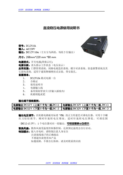
型号:DC12V10A
输入:AC220V
输出:DC12V/10A (左右分为两组,每组5位输出)
尺寸:268mm*220 mm *80 mm
电源型式:开关电源(带指示灯)
电源功能:表头指示工作状态(电压显示)
应用范围:门禁管理系统、闭路电视监控系统、楼宇对讲系统、防盗报警系统及其 它弱电系统,适用于建筑物墙壁挂式安装,带安装孔。
装箱清单:
1、 DC12V10A 箱式电源一台
2、 合格证
3、 使用说明书
4、 电源输入线
5、 备用保险管壹只(在输入插座内)
6、 机箱钥匙贰把
输出端子接线图例:
输出电压调节:在机箱电路板有标着VR1的正方形蓝色可调电位器,可用十字螺丝刀轻轻调节,顺时针旋转电压增高,逆时针旋转电压降低,可调范围(DC12-15.5V ),1个电位器对应一组输出,可根据需要分别调节。
散热风扇:散热风扇受温度控制器控制,达到预定温度会自行启动。
特别提示:接入市电时,请特别注意人身安全
注意接线端子的正确接法
不要超负荷使用本产品
如遇故障,不要自行拆卸,请及时联系供应商
电源输出DC12 V (上面5个为一组,DC+) 电源输出DC12V (上面5个为一组, DC+) 电源输出DC12 V (下面5个为一组,DC -) 电源输出DC12V (下面5个为一组, DC -)。
电源麦威MPS-300X

2.2.7实际输出电压电流显示精 度:三位A/D转换数字显示±1%+2个字。
2.2.8预设输出电压电流显示精 度:三位A/D转换数字显示±1%+8个 字。
2.3 追踪操作
2.3.1 并 联模 式
电 源效 应:CV≤0.01%+3mV 负 载效 应:CV≤0.01%+3mV(Ⅰ ≤3A) CV≤0.02% +5mV( Ⅰ>3A) 2.3.2 串 联模 式 电 源效 应:CV≤0.01% +5mV 负 载效 应:CV≤300mV 正 负电 源输出 时从动 路追踪 误差(Tracking error) ≤ 主动路 输出× 0.5%+10mV
本系列 直流电源为LED显 示,可同时 显示输出电压和电 流值,且所 有规格都具有一组 固定5V,3A输出。 其中MPS-300XLK-3、MPS-3303K带 有输出 关断 功能,MPS-300XLP-3、MPS-3303P带 有 输出关断 且 可预设 电压 电 流功 能。
另 外 ,两 路可 调 电源可进 行串联 或 并联使用 , 并由 一路主 电源 进 行电 压或 电 流跟 踪。串 联时 最高输出 电压 可 达两 路 电压 额定 值之和 ;并联时最 大输出 电流 可达两 路 电 流额定 值 之 和。
(11)C.C.指 示灯
:当 主动 路输 出在 恒 流源 状态 时, 此灯 就会 亮。
(12)C.V.指 示灯
:当 从动 路输 出在 恒 压源 状态 时, 此灯 就会 亮。
(13)C.C.指 示灯
:当 从动 路输 出在 恒 流源 状态 时, 或在 并联 追踪 模 式下 的恒 流源 状态 时, 此 灯就 会亮 。
规格如下:
( 表一 )
ZX2005技术规格书

《技术规格书》一.内容1.产品用途及使用范围:本产品可将220V市电电压转换成3V、4.5V、6V直流稳压电源,可作为收音机等小型电器的外接电源,并可对三组1~5节镍鉻或镍氢电池进行恒流充电,性能优于市售一般直流电源及充电器,具有较高的性价比和可靠性,是一种用途广泛的实用充电器。
产品功能及描述:输入电压市电220V,输出电压分三档(即:3V、4.5V、6V),格挡误差为±10%,输出电流(直流):额定值150mA,最大值300mA, 过载、短路保护:故障消除后自动恢复。
充电稳定电流:60mA(±10%)可对三组1~5节5号镍鉻或镍氢电池进行恒流充电,充电时间10~12小时。
2.基本参数:标准5号电池1~5节充电,额定充电电流60mA。
可输出电压分三档(即:3V、4.5V、6V),额定值150mA。
主要技术性能指标:(1)输入电压:AC:~220V输出电压(直流稳压):分三档(即:3V、4.5V、6V),格挡误差为±10%。
(2)输出电流(直流):额定值150mA,最大300mA.(3)过载、短路保护:故障消除后自动恢复。
(4)充电稳定电流:60mA(±10%)可对三组1~5节5号镍鉻或镍氢电池进行恒流充电,充电时间10~12小时。
电源电路图:3.技术要求:K1置正档位时的测量结果理论值3V 4.5V 6V实际值 2.98 4.37V 5.88VK1置负档位时的测量结果理论值3V 4.5V 6V实际值-3V -4.4V -5.9V负载能力:用一个47欧/2瓦以上的电位器作为负载,接到直流电压输出端,串接万用表500mV 档。
调电位器使输出电流为额定值150mA;用连接线替下万用表,测此时输出电压。
将所测电压与上面的值比较,各档电压降均应小于0.3V。
K1 置3V档置4.5V档置6V档输出电压 2.83V 4.37V 5.77V4.产品制作流程图二.其它要求1.对新产品的设计试验:在产品的组装调试过程中进行。
- 1、下载文档前请自行甄别文档内容的完整性,平台不提供额外的编辑、内容补充、找答案等附加服务。
- 2、"仅部分预览"的文档,不可在线预览部分如存在完整性等问题,可反馈申请退款(可完整预览的文档不适用该条件!)。
- 3、如文档侵犯您的权益,请联系客服反馈,我们会尽快为您处理(人工客服工作时间:9:00-18:30)。
直流稳压电源充电器摘要电子设备一般都需要直流稳压电源供电。
这些直流电除了少数直接利用干电池和直流发电机外,大多数是采用把交流电(市电)转变为直流电的直流稳压电源。
所有手机充电器其实都是由一个稳定电源(主要是稳压电源、提供稳定工作电压和足够的电流)加上必要的恒流、限压、限时等控制电路构成。
这次设计的万能充电器为宽电压充电器,具有安装调试方便、工作稳定、耗电省等优点。
它是由市电整流电路、他励振荡电路、高频扼流电路、低压整流电路、充电自动监控电路等部分组成。
在散件的组装过程中除可进一步的学习电子技术外,还可以掌握电子安装工艺,了解测量和调试技术,一举多得。
关键词:直流稳压万能充原理设计目录一、选题背景 (1)1.1设计目的 (1)1.2设计意义 (1)1.3设计的内容要求 (1)1.4发展概况 (1)二、方案论证 (2)2.1直流稳压电源的基本原理 (2)2.2直流稳压电源的种类及选用 (3)三、设计论述 (4)3.1变压器工作原理 (4)3.2.1整流电路 (6)3.2.2滤波电路 (7)3.3稳压电路 (7)四、结果分析 (9)4.1电路的误差分析 (9)4.2稳压电路的质量指标 (10)五、总结 (11)六、致谢 (12)七、附录 (13)参考文献 (15)一、选题背景1.1设计目的1.通过本次课题的设计,掌握模拟电路系统的设计方法,设计步骤。
2.学会直流稳压电源及充电器的设计方法和性能指标测试方法。
3.培养实践技能以及分析和解决实际问题的能力。
1.2设计意义1.通过专业设计,进一步巩固加深所学的基础理论、基本技能和专业知识;2.在专业设计过程中着重培养独立工作、独立思考并运用已学的知识解决实际问题的能力,同时培养独立获取新知识的能力;3.通过专业设计加强对调研调查、资料获取、实验方法、数据资料的综合处理、计算机应用等最基本的工作实践和科研能力的培养。
1.3设计的内容要求1.设计并制作一个连续可调直流稳压电源及充电器,主要技术指标要求(1)输入:交流220V-50Hz(2)最大输出:直流4.25V-150mA2.设计电路结构,画出实用原理电路图,计算确定元件参数,选择电路元件。
3.自拟实验方法、步骤及数据表格。
1.4发展概况自六十年代起,第一台开关电源问世以来,开关电源在世界各国迅速发展,直流稳压电源也顺势而生,但在初期价格较高,直到八十年代,随着元件工艺的成熟,直流稳压电源的价格也日益下降,应用也变的日益广泛。
近几年随着科技的发展,直流稳压电源的工作频率有原来的几十千赫发展到现在的几百千赫,甚至更高。
现在智能化的直流稳压电源也被广泛应用于生产领域,对此的研究开始向高频方面发展。
以美国为首的几个发达国家在这方面的研究已经转向高频下电源的拓扑理论、工作原理、建模分析方法和高频大功率开关器件,高性能集成控制器和功率模块的开发研制方面发展。
我国在此方面的起步较晚,1973年才开始这方面的研究工作,现在主要在小功率单端变换器方面发展较为迅速。
在功率半导体器件及控制集成化方面,与国外同类产品有这很大的差距。
因此,直流稳压电源的研制及应用在此方面与之也从在很大的差距。
近年来,随着微机,中小型计算机的普及和航空航天数据通信,交通邮电等事业的讯速发展,以及为了各种自动化仪器、仪表和设备配套的需要,当代对电源的需要不仅日益增大,而且对电源的性能、效率、重量、尺寸和可靠性以及诸如程序控制、电源通/断、远距离操作和信息保护等功能提出了更高的要求。
对于这些要求,传统的线性稳压电源无法实现,和线性稳压电源相比,稳压电源具有以下的一些优越性:1.效率高2.稳压范围宽3.体积小重量轻4.安全可靠二、方案论证2.1直流稳压电源的基本原理直流稳压电源一般由电源变压器、整流电路、滤波电路及稳压电路所组成,图2-1为直流稳压电源基本原理框图。
图2-1基本原理框图基本原理:1.电源变压器:电源变压器的作用是将220V的交流电压变换为可以提供整流滤波电路所需的电压。
2.整流电路:利用单向导电元件二极管,把50Hz的正弦交流电变换成脉动的直流电。
3.滤波电路:可以将整流电路输出电压中的交流成分大部分加以滤除,从而得到比较平滑的直流电压。
4.稳压电路:稳压电路的功能是使输出的直流电压稳定,不随交流电网电压和负载的变化而变化。
2.2直流稳压电源的种类及选用直流稳定电源按习惯可分为化学电源,线性稳定电源和开关型稳定电源,它们又分别具有各种不同类型:1.化学类稳压电源我们平常所用的干电池、铅酸蓄电池、镍镉、镍氢、锂离子电池均属于这一类,各有其优缺点。
随着科学技术的发展,又产生了智能化电池。
在充电电池材料方面,美国研制人员发现锰的一种碘化物,用它可以制造出便宜、小巧、放电时间长,多次充电后仍保持性能良好的环保型充电电池。
2.线性稳压电源线性稳压电源有一个共同的特点就是它的功率器件调整管工作在线性区,靠调整管之间的电压降来稳定输出。
由于调整管静态损耗大,需要安装一个很大的散热器给它散热。
优点:稳定性高、纹波小、可靠性高、易做成多路、输出连续可调的成品。
缺点:体积大、较笨重、效率相对较低。
3.开关型直流稳压电源与线性稳压电源不同的一类稳压电源就是开关型直流稳压电源,按起开关作用的振荡电路组成形式分有自激开关式和他激开关式;按起稳压控制作用的脉冲占空比形式分有脉宽调制式和频率调制式。
它和线性电源的根本区别在于它的调整管不是工作在线性区,而是饱和区及截止区即开关状态。
开关电源因此而得名。
优点:体积小,重量轻,稳定可靠。
缺点:相对于线性电源来说,电路复杂,成本较高,输出纹波电压大。
下面就一般习惯分类介绍几种开关电源:(1)AC/DC 电源该类电源也称一次电源,它自电网取得能量,经过高压整流滤波得到一个直流高压,供AC/DC 变换器在输出端获得一个或几个稳定的直流电压。
(2)通信电源通信电源其实质上就是AC/DC变换器式电源,只是它一般以直流-48V或-24V 供电,并用后备电池作DC供电的备份,将DC的供电电压变换成电路的工作电压,一般它又分中央供电、分层供电和单板供电三种,以后者可靠性最高。
(3)电台电源电台电源输入AC220V/110V,输出DC13.8V,功率由所供电台功率而定。
为防止AC 电网断电影响电台工作,而需要有电池组作为备份,所以此类电源除输出一个13.8V直流电压外,还具有对电池充电自动转换的功能。
(4)模块电源随着科学技术的飞速发展,对电源可靠性、容量/体积比的要求越来越高,模块电源越来越显示出其优越性。
它工作频率高、体积小、可靠性高,便于安装和组合扩容,所以越来越被广泛采用。
目前,目前国内虽有相应模块生产,但因生产工艺未能赶上国际水平,故障率较高。
AC/DC 模块电源目前虽然成本较高,但从产品的漫长应用周期的整体成本来看,特别是因系统故障而导致的高昂的维修成本及商誉损失来看,选用该电源模块还是合算的。
(5)特种电源高电压小电流电源、大电流电源、400Hz输入的AC/DC电源等,可归于此类,可根据特殊需要选用。
三、设计论述3.1变压器工作原理图3-1为单相变压器原理图。
通常把与电源相连接的绕组称为一次绕组,与负载相连接的绕组称为二次绕组。
为讨论方便,一般规定:凡与一次绕组有关的各量都在其下角标以“1”,而与二次绕组有关的各量都在下角标以“2”,例如,一次、二次电压、电流分别用U1,U2,I1,I2表示,匝数分别用N1,N2表示。
Z图3-1 变压器工作原理当变压器的一次绕组接入交流电压u1时,在一次绕组中便有交流电流流过,并产生交流磁通。
该磁通的绝大部分通过铁心同时穿过一次、二次绕组,称为主磁通;在一次绕组产生的交流磁通中,还有很少一部分通过周围空气闭合,称为漏磁通。
通常漏磁通很少,为讨论问题方便而把它忽略不计。
当主磁通同时穿过一次、二次绕组时,就在两个绕组中分别产生与电源频率相同的感应电动势E1和E2。
当忽略一次、二次绕组的直流电阻和漏电磁通时,有U1=E1,U2=E2,U1/U2=E1/E2=N1/N2=K式中,K为变压器的变化,即变压器一次、二次绕组的匝数之比。
上式表明,变压器一次、二次侧的电压之比等于匝数之比。
当K>1时,U1>U2,为降压变压器;当K<1时,U1<U2,为升压变压器。
由以上分析可知,变压器从电网上吸收能量并通过电磁感应,以另一个电压等级把电能输送给负载。
在这个过程中,变压器只起到能量的传递作用。
根据能量守恒定率,在忽略了损耗的情况下,变压器输入、输出的视在功率相等,即U1I1=U2I2I1/I2=U2/U1=1/K上式表明,变压器在改变电压的同时,电流也随之成反比例地变化,且一次、二次电流之比等于匝数之反比,即变压器具有变流功能。
3.2整流滤波电路整流电路将交流电压变换成脉动的直流电压。
再经滤波电路滤除较大的纹波成分,输出纹波较小的直流电压。
常用的整流滤波电路有单相半波整流滤波、全波整流滤波、桥式整流滤波等。
各滤波电容C满足R L C=(3~5)T/2,其中T为输入交流信号的周期,R L为整流滤波电路的等效负载电阻。
图3-2整流滤波电路图3.2.1整流电路图3-3 是单相半波整流电路图,电路由电源变压器T、整流二极管V和负载电阻R L组成。
1.工作原理当电源变压器T的初级接交流电压为u1时,在次级就感应出交流电压就为u2,它的瞬时表达式是u2=1.414U2sinωt式中u2为瞬时值,U2 是交流电压有效值,ω为角频率,ωt为相位角。
当u2为正半周即为正值时,二极管V导通,电流i V自上端经二极管V、自上而下的流过负载R L到下端,因为二极管正向压降很小,可认为负载两端电压u L与u2几乎相等,即u L≈u2。
当u2为负半周即为负值时,二极管V截止,通过负载R L上的电流i V=0, 负载上的电压u L =0。
可见,在交流电u2工作的全周期内,R L上只有自上而下的单方向电流实现了整流。
u2、u L、i L 相应的波形如图3-3(b)所示。
可以看出他们的图3-3单相半波整流电路大小是波动的,但方向不变.这种大小波(a)电路(b)波形动但方向不变的电压和电流,称为脉动直流电(它的波形不平滑,通常称为含有交流成分或纹波成分)。
由u L 的波形可见,这种电路仅利用了电源电压u2 的半个波,故称为半波整流电路,它输出的是半波脉动直流电。
2.负载及二极管上的电压和电流半波整流输出的电压或电流是用半波脉动直流电压或电流的平均值表示的。
理论和实验都证明,负载两端电压u L与变压器次级电压有效值U2 的关系是u L=0.45 U2流过负载的电流i L是i L=u L/R L=0.45 U2/R L由电路图可知,流过整流二极管的正向工作电流i V 和流过负载R L 的电流i L相等,即i V=i L=0.45 U2/R L当二极管截止时,它承受的反向峰值电压u RM 是u2 的最大值,即u RM≈1.41 U2选用半波整流二极管时应满足下列两个条件:(1)二极管允许的最大反向电压应大于承受的反向峰值电压;(2)二极管允许的最大整流电路应大于流过二极管的实际工作电流。