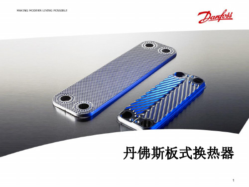
丹佛斯板式换热器样本
丹佛斯PVG 100比例阀中文样本

修订内容 更改代码 新的封底 添加4页: 应用安全章节 大幅修订 大幅修订
版本号 CD CF DA DB EA
样本修订
PVG产品的样本修订
名称 PVG 32 农机模块-公制油口 PVG 100 比例阀 PVG 120 比例阀 PVBZ 基本模块 PVSK 模块,集成了分流和P口切断功能 PVED-CC 电控模块 PVED-CX 电控模块,系列 4 PVE 系列 4 PVPV / PVPVM 泵侧模块 PVHC 电控模块,用于PVG32和PVG100 PVGI 过渡模块 PVSP/M 优先模块 PVBM “Meter-in” “Meter-out” 模块 类型 产品样本 维修手册 产品样本 产品样本 产品样本 产品样本 产品样本 产品样本 产品样本 产品样本 产品样本 产品样本 样册 代码 11051935 11048807 520L0356 520L0721 520L0556 520L0665 11070179 520L0553 520L0222 11064912 520L0405 520L0291 L1117392
PVG 100 功能
PVG 100 阀组带开芯 PVPF .............................................................................................................................................9 PVG 100 阀组带闭芯 PVPV / PVPVP / PVPVM ....................................................................................................... 11 PVG 100 闭芯转向优先模块 PVPVP ................................................................................................................. 12 PVG 100 闭芯模块 PVPVM ................................................................................................................................... 12 PVG 100 工作模块 PVB ........................................................................................................................................... 12 PVG 100 回油模块 ................................................................................................................................................... 12 负载敏感控制................................................................................................................................................................... 14 远程压力补偿控制 ......................................................................................................................................................... 15 远程压力补偿系统特性: ........................................................................................................................................ 15 典型实例:远程压力补偿系统........................................................................................................................... 15 PVG 100 主阀芯,带压力补偿控制......................................................................................................................... 16 压力补偿系统特性 ................................................................................................................................................... 16 典型实例:压力补偿系统 .................................................................................................................................... 16 PVMR, 摩擦定位 .............................................................................................................................................................. 17 PVMF, 机械浮动位置锁定. ......................................................................................................................................... 17 PVBS, 流量控制主阀芯 (标准)................................................................................................................................. 18 PVBS, 流量控制主阀芯 (线性特性) ............................................................................................................................. 18 安全建立 ............................................................................................................................................................................ 19 FMEA (故障模式及影响分析) IEC EN 61508 ................................................................................................... 19 故障模式及影响分析 ISO 12100-1 / 14121..................................................................................................... 19 实例:控制系统. ........................................................................................................................................................... 20 PVG 100 – LS卸荷或先导油切断可选 ............................................................................................................... 22
机组特点介绍
Danfoss电动调节阀
• • • • • • • • •
降低能源消耗
降低噪音
水泵与管道寿命长 水泄漏降至最低
增强型电压矢量控制 SPWM脉宽调制 供电电压可以额定输出 电压低降容运行 无需电机运行就可测量电机的参数,并修正变频器原有的数据模型 在电机运行状态下检测 , 电机必须与负载断开 可保证电机转矩的最佳性能 . 电机不必与负载断开 内部控制功能 能量自动优化 比通用变频器多节能 5-10% 与 FC100类似 PID 调节器 双通道 PID控制 双通道 PID控制 实时钟控制 操作简单 操作较复杂 ,不便于编程 参数调整 大多数参数在变频器运行时可调整 调整参数时变频器须停止 电源谐波抑制 均内置双直流电抗器,满足 >37kw内置交流电抗器 ,效果与 FC100系列类似 ,但会有 1.5% 左右的压降 , EZ61000-3-2和 IEEE-519 的要求 在 50HZ,满载情况下会电机温度会更高 ,影响电机寿命 ≤37kw内置直流电抗器 无线电干 均内置 RFI滤波器 部分内置 ,部分只能外置 . 同等情况下 ,无线电干扰噪声总体较 FC100高 扰滤波器 有抗无线电干扰要求情况下 : 有抗无线电干扰要求情况下 : (电磁兼容性 ) 电机电缆 (屏蔽 )150米内达到 EN55011-1 A级 (RFI滤波器内置 ) 电机电缆 (屏蔽 )30米内达到 EN55011-1 A级 电机电缆 (屏蔽 )50米内达到 EN55011-1 B级 (RFI滤波器外置 ) 电机电缆 (屏蔽 )30-100米内达到 EN55011-1 A级 无抗无线电干扰要求情况下 : 无抗无线电干扰要求情况下 : 最大电缆长度可达 300米 (无屏蔽 ) ≤5.5kw最大电缆长度 100米 ;7.5KW-37KW 最大电缆长度 200米 45kw-90kw最大电缆长度 300米 保护功能 电机保护 100% 输出相间、相地短路保护 功能较少 风扇保护 冷却风扇自动控制 冷却风扇无控制 ,风扇设计寿命为三年 安装 一体化设计 ,安装简单 与 FC100相比 ,安装相对耗时 .安装需小心避免电器元件受损 (安装过程中 需取下外罩 ) 进口 /国产 进口 国产
3 丹佛斯机组及主要部件介绍

Danfoss 换热机组及部件介绍丹佛斯区域能源技术部户用小型换热机组多户用小型换热机组大型换热机组中型换热机组Danfoss 机组产品全系列机组产品全系列、、多功能设计通常要考虑设计通常要考虑::机组本身热负荷参数等 机组整体结构 客户特殊需求,如布置空间、噪音等 机组所处热力系统的水力工况设计方案量体裁衣设计方案量体裁衣,,关注客户利益机组优化设计软件机组优化设计软件,,资深的专业技术人员三维三维设计设计设计,,结构紧凑结构紧凑,,优化布局优化布局,,维修方便优化的专业设计着重细节着重细节,,追求完美细微之处见真功细微之处见真功,,Danfoss 的设计细致到每个细节的设计细致到每个细节,,精益求精精益求精。
精心选择测点位置精心选择测点位置,,保证数据采集真实准确排气装置排污装置卸压装置完备的排气完备的排气、、排污及安全卸压装置排污及安全卸压装置,,保证机组稳定运行着重细节着重细节,,追求完美细微之处见真功细微之处见真功,,Danfoss 的设计细致到每个细节的设计细致到每个细节,,精益求精精益求精。
着重细节着重细节,,追求完美细微之处见真功细微之处见真功,,Danfoss 的设计细致到每个细节的设计细致到每个细节,,精益求精精益求精。
过滤器本体具有压差检测功能过滤器的精巧设计,使得压差检测功能变得简单容易恶劣水力工况下,采用压差控制装置确保机组的温度稳定调节。
机组配置80%以上是 以上是Danfoss产品 机组配置 以上是 产品Danfoss换热器Danfoss电动调节阀Danfoss ECL 控制器Danfoss温度/压力传感器Danfoss超声波热量表Danfoss球阀Danfoss变频器Grundfos水泵Danfoss板式换热器 板式换热器• 板片厚度:0.5mm • 沟槽深度:2.8~3.9mm • 板片材质:AISI304 AISI316 • 密封垫片:NBR(丁晴) EPDM(三元乙丙) • 接口尺寸:DN32~DN300 • 接口方式:螺纹连接 法兰连接Danfoss板式换热器 板式换热器方便安装的免粘接垫片 独特的定位系统一次冲压成形确 保板片精度独特的紧固螺栓设计 卓越的导流区设计Danfoss球阀 球阀• 免维护 • 阀体为整体焊接件,易打开和关闭 • 阀门关闭严密,操作轴密封严密 • 低阻力,减少水泵能耗操作轴处的密封严密 阀门关闭严密Danfoss电动调节阀 电动调节阀• 流通能力高 • 流量特性为等百分比特性,控制性能好 • 有自检阀门行程的功能, 减少调试时工作量 • 泄漏率低 • 易于安装和操作 • 可手动操作(电手动和机械手动) • 最大口径达到DN250,最高耐温可达350℃ • 可实现控制信号分割功能 • 故障自诊断功能Danfoss电动调节阀 电动调节阀驱动器功能(AME 10/20/30/15/25/35/55/85系列 系列) 驱动器功能 系列U 2V...---V Direct 0(2)V...5(6)V Proportional LOG. flow 100% Kvs Reset1 2 3 4 5 6 7 8 9---I 0V...---V Inverse Sequential 5(6)V...10V 3 point / RL LIN. flow Red. Kvs ResetDanfoss电动调节阀 电动调节阀I• 控制信号的选择 • 控制信号起点 • 正反向动作A A B A B A B AB1U1A BA BABBABABAAB B2 (0)10V4 (0)UI20mA0V...---V0V...---VInverse11112V...---V2V...---VDirectABABABABA BABA BABA BABA BABABABABABA BABAAB BA BABAAB B0 02 410 20V mA0 010 20V mA0 010 20V mA0 0DirectInverse10 20V mADanfoss电动调节阀 电动调节阀•控制信号分割功能当两个调节阀并联时Sequential 5(6)V...10V Sequential 5(6)V...10V1A B A B AB A B A AB B1---0(2)V...5(6)VABA BABABA BAB0 05 1010 20V mA0 05 100(2)V...5(6)V---10 20V mADanfoss电动调节阀 电动调节阀• 模拟量控制和三点控制合为一体 AMV,AME3 point / RL 3 point / RL6A B6ProportionalAB24VACA BABA BABABABProportional24VACA B AB A AB B0 010 20V mADanfoss电动调节阀 电动调节阀• 改变阀门特性功能线性、等百分比特性LIN. flow77A BLOG. flowABA BABA BABABABA BABAAB B0 010 20V mA0 0LOG. flowLIN. flow10 20V mADanfoss电动调节阀 电动调节阀• Kvs值限制功能DN125 Kvs=220 DN150 Kvs=320 计算Kv=270? 建议当所选调节阀的Kvs值大于计算Kv 值20%以上时应用此功能Red. Kvs81A B8100% KvsABA BABAAB B100% Kvs100% KvsRed. Kvs82% KvsABABA BABAAB B0 010 20V mA0 010 20V mADanfoss压差控制器 压差控制器压差控制器工作原理MDV压差控制器是在水系统中用来保持某两点间压 差恒定的自力式控制阀,一般由阀体,驱动膜盒, 导压管等部分组成. 其工作原理如左图所示(左图为压差控制器控 制电动调节阀两端的压差): 电动调节阀(MDV)上游的高压通过导压管引 导至控制膜盒下侧. 电动调节阀下游的压力通过外部导压管或内部 导压孔引导至控制膜盒上侧. 由压差引起的作用力与内部弹簧的作用力相互 平衡,使调节阀两端的压差保持恒定.压差控制器侧压高侧压中侧压低调节弹簧的预紧力,即可调节压差设定值.Danfoss压差控制器 压差控制器为什么使用差压控制器?• 保持电调阀两端压差恒定——保证调节阀的调节特性,使控温准确 ——减少调节阀动作次数,延长使用寿命 ——限制全开时最大流量,反之全开时近端热站 局部“抢水”(热权度小于1)• 保证电调阀在较低的压差下工作——防止电调阀两端压差超过其最大关闭压差 ——防止出现气穴现象,降低噪音Danfoss变频器 变频器FC100系列 变频器 系列• 专为水泵、风机的应用而设计制造 • 电压矢量控制模式 • 优化的谐波性能,内置双直流电抗器 • 最佳的EMC特性,内置射频干扰滤波器 • 自动能量优化功能 • 电机自适应功能 • 双通道PID调节 • 电机友好性 • 完全的自身及电机保护 • 水泵专用功能管网水力补偿功能/无流量检测功能/睡眠功能降低能源消耗 降低噪音 水泵与管道寿命长 水泄漏降至最低Danfoss ECL控制器 控制器专用于供热和暖通空调系统的控制器 – ECL200/300 1. 使用简单, 调试时只需设定即可, 勿需任何编程 2. 操作方便, 只需简单培训工人即可操作 3. 安装简便, 运行可靠性高 4. 性价比高功能强大的可编程控制器 – ECL Apex 20 1. 使用灵活, 扩展性强 2. 组网方便, 本地化的HMI界面Danfoss ECL控制器 控制器• 气候补偿 • 分时控温 • 一次网回水温度限制 • 优化控制 • 室内温度影响ECL 200/300•功能专一,使用方便简单 • 气候补偿供暖控制或生活热水恒温控制, 根据室外温度 调节供水温度,节能舒适. •分时供暖 •PI 控制,三点可控硅输出。
丹佛斯板式换热器介绍ppt课件
Apr. 15 2011
11
丹佛斯钎焊式板式换热器
换热量:1 KW to 450 KW 使用温度:-195oC to +200oC 设计压力: 50 bar 板片材料: AISI 304L,316L,SMO 254 钎焊方式:铜焊,镍焊 接管: 螺纹,焊接,卡口等 应用领域:制冷、空调、供热、液压等
Apr. 15 2011
3
板式换热器中国工厂
丹佛斯(杭州)
2006年9月丹佛斯收购杭州钦宝后成立 丹佛斯全资子公司,约200名员工 地处杭州下沙经济开发区,工厂约
10000平方米
丹佛斯(贵阳) 2010年2月全资收购 约110名员工 致力于钎焊式板式换热器研发
MaMnaunfuafaccttuurringg PrPorcoceessssees
Apr. 15 2011
成熟的生产工艺
• Just-in-time concept • Supply Chain Management (Kaizen)
Apr. 15 2011
8
板型和通道类型
板型
H
L
通道类型
H
L
M
(MH & ML)
大夹角
小夹角
两大夹角组
合
合
两小夹角组
板片的角度和冲压深度影响着压降和热力性能。 通过对角度和冲压深度的组合可以使板片处于最佳性能。
大小夹角组合
REFRIGERATION & AIR CONDITIONING
Apr. 15 2011
前端板: 水侧 Q1-Q2 制冷剂側 Q3-Q4
H4 H1
Q1 Q4
Q6
H3 H2
Q2 Q5
danfoss kp71 温度开关内部结构图
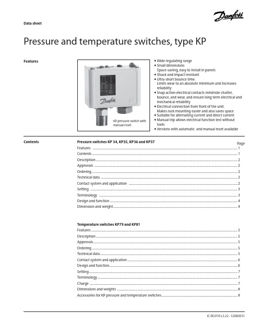
Data sheetIC.PD.P10.L3.22 - 520B3031Pressure and temperature switches, type KPFeatures• Wide regulating range • Small dimensionsSpace-saving, easy to install in panels • Shock and impact resistant • Ultra-short bounce time.Limits wear to an absolute minimum and increases reliability• Snap action electrical contacts minimize chatter,bounce, and wear, and ensure long term electrical and mechanical reliability• Electrical connection from front of the unit.Makes rack mounting easier and also saves space • Suitable for alternating current and direct current • Manual trip allows electrical function test without tools• Versions with automatic and manual reset availablePressure switches KP 34, KP35, KP36 and KP37PageFeatures .........................................................................................................................................................................................1 Contents ..........................................................................................................................................................................................1Description .....................................................................................................................................................................................2Approvals .......................................................................................................................................................................................2 Ordering ..........................................................................................................................................................................................2 Technical data ...............................................................................................................................................................................2 Contact system and application ...........................................................................................................................................2 Setting ............................................................................................................................................................................................3 Terminology .................................................................................................................................................................................3 Design and function ...................................................................................................................................................................4 Dimension and weight ...............................................................................................................................................................4 Temperature switches KP79 and KP81 Features ...........................................................................................................................................................................................5Description .....................................................................................................................................................................................5 Approvals ........................................................................................................................................................................................5 Ordering ..........................................................................................................................................................................................5 Technical data ................................................................................................................................................................................5 Contact system and application .............................................................................................................................................6 Design and function ....................................................................................................................................................................6 Setting ..............................................................................................................................................................................................7 Terminology ...................................................................................................................................................................................7 Charge .............................................................................................................................................................................................7 Dimensions and weights ..........................................................................................................................................................8Accessories for KP pressure and temperature switches .................................................................................................8 KP pressure switch with manual resetContentsDanfoss KP temperature switches are used for regulating, monitoring and alarm systems inKP thermostats are temperature-operated electricDimensions and weights©D a n f o s s A /S 07-2007, A C -D S L , m rAccessoriesfor KP pressure and temperature switches8 IC.PD.P10.L3.22 - 520B3031Danfoss can accept no responsibility for possible errors in catalogues, brochures and other printed material. Danfoss reserves the right to alter its products without notice. This also applies to products already on order provided that such alterations can be made without subsequential changes being necessary in specifications already agreed.All trademarks in this material are property of the respective companies. Danfoss and the Danfoss logotype are trademarks of Danfoss A/S. All rights reserved.。
Danfoss热力膨胀阀样本参数
Danfoss A/S (RC-CM/hbs), 10 - 2002
RK0YP102
3
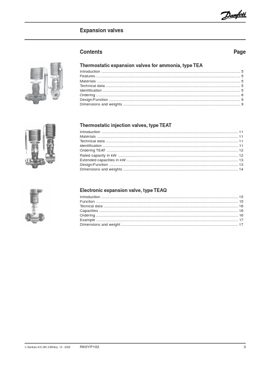
Introduction
Thermostatic expansion valves for ammonia type TEA
Thermostatic expansion valves regulate the injection of refrigerant liquid into evaporators. Injection is controlled by the refrigerant superheat.
Thermostatic injection valves, type TEAT
Introduction .............................................................................................................................. 11 Materials .................................................................................................................................. 11 Technical data .......................................................................................................................... 11 Identification ............................................................................................................................. 11 Ordering TEAT ......................................................................................................................... 12 Rated capacity in kW ............................................................................................................... 12 Extended capacities in kW ....................................................................................................... 13 Design/Function ....................................................................................................................... 13 Dimensions and weights .......................................................................................................... 14
丹佛斯(Danfoss)温控阀 ORV DKRCI.PD.HP0.B9.02 → DKRCI.PD.
ORV are 3-way industrial valves for maintaining a constant oil temperature in gas compressor systems, by mixing hot and cold oil in the lubricating system of e.g. screw or turbo type compressors.The ORV valves are with few components and with extended cylindrical connections, to ensure ease of installation and service.Features• Stainless steel nickel plated thermostaticelement.• Butt-weld (DIN, ANSI) or socket weld (SOC)connection.• No manual adjustment.• Plug and Play design.• Optimised flow characteristics.• Sturdy construction.• High resistance against vibrations or shock.• Can be mounted in any direction.• Service friendly. Easy to dismantle and service when required.• Classification: DNV, CRN, BV, EAC etc.To get an updated list of certification on the products please contact your local Danfoss Sales Company.Technical data Oils:Applicable to all common refrigeration oils.Refrigerants:Applicable to HC, HCFC, HFC, R717 (Ammonia)and R744 (CO2).For further information please refer to installationinstruction for ORV.Temperature range:Minimum operating temperature:≥ –10°C (+14°F)Max. temperature limit based on the element temperature settings:Types Max limit43°C / 110°F77°C / 170°F49°C / 120°F82°C / 180°F60°C / 140°F93°C / 200°F77°C / 170°F110°C / 230°FPressure range:The valves are designed for a max.working pressure of 40 bar g (580 psig)Design IdentificationConnectionsAvailable with the following connections:• Butt weld DIN (EN 10220),DN 25-80 (1-3 in.)• Butt weld ANSI (B 36.10 Schedule 80),DN 25 - 40 (1 - 1½ in.)• Butt weld ANSI (B 36.10 Schedule 40),DN 50 - 80 (2 - 3 in.)• Socket Weld (ANSI B 16.11),DN 25 - 50 (1 - 2 in.)HousingMade of special, cold resistant steel approved forlow temperature operations.InstallationInstallation of the valve depends on the way itshould operate.Pressure Equipment Directive (PED)ORV valves are approved according to theEuropean standard specified in the PressureEquipment Directive and are CE marked.For further details / restrictions - see InstallationInstruction.FunctionMixing operationORV valve can work as a mixing or diverting valve. The ORV temperature regulating valve utilises the high coefficient of thermal expansion of wax to create the internal movementnecessary to have a cold and a hot inlet mixing to a common outlet. The outlet temperature will correspond to the nominal temperature of the thermostatic element.The valve house has three ports:• Port A is used for the common outlet • Port B is for the hot inlet •Port C is for the cold inletWhen the compressor unit is cold at start up, the thermostatic element will be contracted to let the full flow from port B pass until the nominal temperature (minus 5 K / 10°F ) is reached (fig. 1.1). The thermostatic element will then begin to extract to let the outlet become a mixture of hot and cold oil.When the nominal temperature is reached, the element is positioned in approximately half open position (fig. 1.2). If the temperature is reaching approximately the nominal temperature plus 5 K, the thermostatic element has been extracted to its fully open position (fig. 1.3). In this position the oil temperature will only come from the cold inlet port (C) from oil cooler.From figure 1, it can be seen how the sleeve on the element is sliding in a vertical movement. The thermostatic element is kept in position by a spring.Diverting operationDiverting operation is similar to the mixing operation. It is carried out with separation in to two of the fluid with single temperature. Due to that the temperature on the inlet is very stable fact the regulation is very smooth. The inlet temperature would correspond to the nominaltemperature of the thermostatic element.The valve house has three ports:• Port A is used for the common inlet • Port B is for the cold outlet • Port C is for the warm outletThe diverting operation otherwise is similar to the mixing operation.Application examplesExample of the system with ORV for diverting operationCapacitiesSI unitsSelection exampleOil type: Grade 68Required flow: 17 m3/hNominal oil temperature: 49°CPipe dimension: 40 mmThe upper left curve shows the viscosity of different grades of oil as a function of the temperature. The viscosity is continued into the upper right curve where the 17 m3/h must be found. The line is drawn vertically downwards into the capacity table for the ORV valve models.As shown two selections can be made:Either ORV 40 H2 with pressure drop at approx. 0.56 bar or ORV 50 H2 with pressure drop at 0.42 bar.The final selection will depend on the available pressures in the system. If the pressures are low (or can be low at certain loads) the ORV 50 H2 might be preferred. If the pressures are constantly available the pipe dimension may be taken into account and the ORV 40 H2might be preferred.CapacitiesUS unitsSelection exampleOil type: Grade 68Required flow: 75 USgal/min.Nominal oil temperature: 120°FPipe dimension: 1½”The upper left curve shows the viscosity of different grades of oil as a function of the temperature. The viscosity is continued into the upper right curve where the 75 USgal/min. must be found. The line is drawn vertically downwards into the capacity table for the ORV valve models.As shown two selections can be made:Either- ORV 1½H2 with pressure drop 8.2 psi or- ORV 2”H2 with pressure drop 6.2 psiThe final selection will depend on the available pressures in the system. If the pressures are low (or can be low at certain loads) the ORV 2" H2 might be preferred. If the pressures are constantly available the pipe dimension may be taken into account and the ORV 1½" H2might be preferred.Material specification ORV 25-80No.Part Material EN ASTM standard1Housing Steel GP240GH10213-2WCB A 2162Cover Steel GP240GH------------------------P285QH 10213-2------------------------10222-4WCB A 216------------------------A 3503Glide ring PTFE4Element*)Stainless steeland NI platedparts5Spring Steel DIN1722310270-16Gasket Non asbestos7Bolts Steel Quality 8.8ISO4017Grade 5*) The thermostatic element may look differently from one shown on the picture. All types of thermostats used by Danfoss have the same function, temperature setting and P-band.Connections DINANSISOCDimensions and weightsType codesImportant!Where products need to be certified according to specific certification societies or where higher pressures are required, the relevant information should be included at the time of ordering.Valve type ORV Oil regulating valve, high specificationNominal size in mm(valve size measured on the connection diameter)Available connections DINANSI SOC 25X X X 40X X X 50X X X65X X 80XXConnection A D SOC Butt weld connection: ANSI Butt weld connection: DIN Socket welding Valve housing3-WAY3-WAYThermostatCode no.Thermostat 43oC/110oFORV 25 and ORV 40 H1148H3466ORV 40 and ORV 50 H2148H3467ORV 65 and ORV 80 H3148H34681)Thermostat 49o C/120oFORV 25 and ORV 40 H1148H3463ORV 40 and ORV 50 H2148H3464ORV 65 and ORV 80 H3148H34651)Thermostat 60o C/140oFORV 25 and ORV 40 H1148H3469ORV 40 and ORV 50 H2148H3470ORV 65 and ORV 80 H3148H34711)Thermostat 77o C/170oFORV 25 and ORV 40 H1148H3472ORV 40 and ORV 50 H2148H3473ORV 65 and ORV 80 H3148H34741)1)For valve housing size H3 the code number includes two H2 thermostats.Complete valve housing including gasket and guide ring but without thermostat Code no.ORV 25 DIN H1148H3399ORV 25 SOC H1148H3400ORV 25 ANSI H1148H3401ORV 40 DIN H1148H3361ORV 40 DIN H2148H3402ORV 40 SOC H2148H3403OVR 40 ANSI H1148H3404ORV 40 ANSI H2148H3405ORV 50 DIN H2148H3406ORV 50 SOC H2148H3407ORV 50 ANSI H2148H3408ORV 65 DIN H3148H3409ORV 65 ANSI H3148H3410ORV 80 DIN H3148H3362ORV 80 ANSI H3148H3411ORV parts programmeExample:ORV 40 DIN H2 49°C/120°F:Thermostat element and cover gasket code number 148H3464andComplete valve housing code number 148H3402Ordering ORV valves from the parts programmePlease note:The thermostat code numbers do not include guide ring.Gasket and guide ring are included when ordering the complete valve housing but can also be ordered separately as spare parts.PartSpare parts for Code no.Gasket and guide ringORV 25 and ORV 40 H1148H3246ORV 40 and ORV 50 H2148H3247ORV 65 and ORV 80 H3148H32482)2)Including two guide rings and one gasket.ORV spare partsData sheet | Temperature regulating valve, type ORV。
丹佛斯XB系列板式换热器-英文版
Approvals: • CE certificate according (PED) 97/23/EC • GOST/ Russia • SVGW/Switzerland • VA/Denmark
DH-SMT/FI
VD.KA.E7.02 © Danfoss 05/2009
1
Data sheet
Type
XB 51H-1 XB 51L-1 * XB 51H-1 SB * XB 51H-1 SB * XB 51L-1 SB * XB 51L-1 SB XB 60-12) * XB 60-1 SB XB 70L-12) XB 70M-12) XB 70H-12)
Thread
Connection
Thread G2A
-
-
004B1705 004B1605 004B1706 004B1608 004B1707 004B1708 004B1709 004B1710 004B1711 004B1712 004B1714 004B1715 004B1717 004B1718 004B1719 004B1720 004B1610 004B1613 004B1615 004B1618 004B1620 004B1625 004B1630 004B1635 004B1645 004B1650 -
XB 10-2 Thread G1A 004B3010 004B3013 004B3015 004B3018 004B3020 004B3023 004B3025 004B3028 004B3030 -
XB 20-2 Thread G1A 004B3220 004B3223 004B3225 004B3228 004B3230 -
Hale Waihona Puke Brazed heat exchanger, XB
丹佛斯 MicroChannel 热交换器 MCHE 2 安装和维护手册说明书
User manualInstallation, Operation and Maintenance ManualAPP pumps (APP 21-43)Service guideMicroChannel Heat Exchangers MCHEInstallation and Maintenance Guide Sevice guide | Application, Installation and Maintenance Manual MCHE2 |AX292455807588en-000101 | 01.2019Table of ContentsTable of Contents . . . . . . . . . . . . . . . . . . . . . . . . . . . . . . . . . . . . . . . . . . . . . . . . . . . . . . . . . . . . . . . . . . . . . . . . . . . . . . . . . .21 . Introduction . . . . . . . . . . . . . . . . . . . . . . . . . . . . . . . . . . . . . . . . . . . . . . . . . . . . . . . . . . . . . . . . . . . . . . . . . . . .41 .1 G eneral . . . . . . . . . . . . . . . . . . . . . . . . . . . . . . . . . . . . . . . . . . . . . . . . . . . . . . . . . . . . . . . . . . . . . . . . . . . . . . . . .41 .2 Symbols . . . . . . . . . . . . . . . . . . . . . . . . . . . . . . . . . . . . . . . . . . . . . . . . . . . . . . . . . . . . . . . . . . . . . . . . . . . . . . . .42 . Storage and working environments . . . . . . . . . . . . . . . . . . . . . . . . . . . . . . . . . . . . . . . . . . . . . . . . . . . . .52 .1 Storage . . . . . . . . . . . . . . . . . . . . . . . . . . . . . . . . . . . . . . . . . . . . . . . . . . . . . . . . . . . . . . . . . . . . . . . . . . . . . . . .52 .2 Handling . . . . . . . . . . . . . . . . . . . . . . . . . . . . . . . . . . . . . . . . . . . . . . . . . . . . . . . . . . . . . . . . . . . . . . . . . . . . . . .52 .3 Bending procedure . . . . . . . . . . . . . . . . . . . . . . . . . . . . . . . . . . . . . . . . . . . . . . . . . . . . . . . . . . . . . . . . . . . . .53 . Installation . . . . . . . . . . . . . . . . . . . . . . . . . . . . . . . . . . . . . . . . . . . . . . . . . . . . . . . . . . . . . . . . . . . . . . . . . . . . . .63 .1 Pass arrangement . . . . . . . . . . . . . . . . . . . . . . . . . . . . . . . . . . . . . . . . . . . . . . . . . . . . . . . . . . . . . . . . . . . . . .63 .2 Fan location and size . . . . . . . . . . . . . . . . . . . . . . . . . . . . . . . . . . . . . . . . . . . . . . . . . . . . . . . . . . . . . . . . . . . .63 .3 Coil mounting against thermal expansion . . . . . . . . . . . . . . . . . . . . . . . . . . . . . . . . . . . . . . . . . . . . . . .73 .4 Elimination of gaps . . . . . . . . . . . . . . . . . . . . . . . . . . . . . . . . . . . . . . . . . . . . . . . . . . . . . . . . . . . . . . . . . . . . . .83 .5 Prevention of galvanic corrosion . . . . . . . . . . . . . . . . . . . . . . . . . . . . . . . . . . . . . . . . . . . . . . . . . . . . . . . . .83 .6 Vibration . . . . . . . . . . . . . . . . . . . . . . . . . . . . . . . . . . . . . . . . . . . . . . . . . . . . . . . . . . . . . . . . . . . . . . . . . . . . . . .94 .Leak repair . . . . . . . . . . . . . . . . . . . . . . . . . . . . . . . . . . . . . . . . . . . . . . . . . . . . . . . . . . . . . . . . . . . . . . . . . . . . . .95 . Coating . . . . . . . . . . . . . . . . . . . . . . . . . . . . . . . . . . . . . . . . . . . . . . . . . . . . . . . . . . . . . . . . . . . . . . . . . . . . . . . .106 Maintenance . . . . . . . . . . . . . . . . . . . . . . . . . . . . . . . . . . . . . . . . . . . . . . . . . . . . . . . . . . . . . . . . . . . . . . . . . . .106 .1 Filters . . . . . . . . . . . . . . . . . . . . . . . . . . . . . . . . . . . . . . . . . . . . . . . . . . . . . . . . . . . . . . . . . . . . . . . . . . . . . . . . . .106 .2 Shut down periods . . . . . . . . . . . . . . . . . . . . . . . . . . . . . . . . . . . . . . . . . . . . . . . . . . . . . . . . . . . . . . . . . . . . .106 .3 Cleaning procedure . . . . . . . . . . . . . . . . . . . . . . . . . . . . . . . . . . . . . . . . . . . . . . . . . . . . . . . . . . . . . . . . . . ..10Service guide | Application, Installation and Maintenance Manual MCHE3AX292455807588en-000101 | 01.2019 |1.1 Gener a lThis guide is for installation and maintenance of Danfoss Microchannel Heat Exchangers (MCHEs) . We recommend that you read this manual carefully before commencing any work .Danfoss is not responsible or liable for any damage caused by failure to comply with the instructions in this manual and/or due to incorrect installation, operation and mainte-nance of MCHEs .All personnel being responsible for operation and maintenance of theeat exchanger unit must read and fully understand these instruc-tions before:• Transportation of the MCHE unit • Lifting the unit• Installing the MCHE unit •S ervicing the MCHE unit • Maintaining the MVHe unit•1.2 Gener alI ndicates something to be noted by thereaderI ndicates a situation which will or could result in personal injury and/or damage to the MCHE1. IntroductionSevice guide | Application, Installation and Maintenance Manual MCHE4 |AX292455807588en-000101 | 01.20192. Storage and workingenvironments• Microchannel heat exchangers should bestored indoors in a dry and clean environ-ment .• The storage temperature range is -40 °C to 121°C (-40°F to 250°F) .•Metal chips, and/or copper or steel dust can cause galvanic corrosion, so storage and installation areas must remain clean and separate from machining or welding areas . Use separate tools and/or keep tools clean .•To minimize potential damage, we recom-mend that you keep MCHEs in their original packaging until they are installed in the air conditioning or refrigeration equipment . •Improper storage and stacking of MCHEs can cause premature corrosion or deforma-tion and will reduce MCHE’s life . Extra care should be taken when storing MCHEs!• Refrigerants used in MCHE shall comply with AHRI Standard 700 .•The maximum operating pressure shall not exceed the value shown on the Label of MCHE .2.1 Stor a ge2.2 H a ndlingCompared to tube & fin coils, microchannel heat exchangers are relatively light, the fins are harder to bend and they are less likely to cut fingers . The combination of these features makes MCHEs easier to handle than tube & fin coils . However, the overall coil assembly is made of soft alu-minum, so it is susceptible to deformation (Fig .1)Fig . 1 Handling attentions2.3 Bending procedureThe same bending machines can be used for MCHE and tube & fin heat exchangers . In order to optimize costs associated with shipping and packaging, we recommend that MCHEs be shipped flat and formed at the customer’s location .Bending Radius:The minimum bend radius required to achieve acceptable manufacturing yields is a function of the microchannel tube, fin, and alloy, the overall capabilities of the bending equipment including, fixturing, bending speed and bending length .NOTE: Conducting trial bending runs of thespecific coil and configuration are recommended to verify . In general, tighter radius, thicker tubes and longer bend lines are harder to bend . Use a larger radius if possible .Recommended minimum bending radii (as determined by factory tests under favorable conditions) are shown in Table 1 for different microchannel tubes and fins . Consult with Danfoss for the tubes not listed . Do notarbitrarily extrapolate or interpolate the values .•Never lift a MCHE by the inlet and outlet tubes as it might result in dimensional deviation or worse yet, the initiation of a crack that can later result in a leak .• Do not hit or drop MCHE on edges . The MCHE is constructed of soft aluminum therefore, dropping, striking, placing heavy objects on top of, or stepping on any part of the heat exchanger will likely cause a deformation . If the coil becomes slightly deformed or bowed, it is possible to flatten them back out by laying them concave side down on a flat hard surface and applying pressure via a large heavy flat plate (say 3-4 square feet of ½” non-metallic sheet, such as plywood or plastic, with a couple of handles attached) . This procedure works for bowed coils with flush fins, but not for local fin protrusions .Table 1Service guide | Application, Installation and Maintenance Manual MCHE5AX292455807588en-000101 | 01.2019 |Consider the following during bending:• MCHEs are constructed of soft aluminumand are susceptible to deformation during handling . Prior to bending operation, make sure the MCHE is flat, square and undam-aged . Consider a sizing operation to ensure this .• Make sure the coils are loaded into thebender in a way that keeps them flat square and undamaged . • Keep the flat tubes perpendicular to thespindle while bending the coil .• Clamp the coil during the bending process,being careful not to crush it . • Slower bending speeds will often yieldbetter results .• Vertical spindle bending machines are oftenset up so that the microchannel coil ends up sliding along the table with all its weight supported by the header ends and/or the bottom dead tube .During the bending operation, do not let one end of the coil become cantilevered off the edge the table, because this can cause the coil to droop with the tubes being non-perpendicular to the spindle, resulting in corkscrewing or reduced bend quality and/or consistency . Note that with some benders, a portion of the supporting table will drop down during bending, creating opportunities for cantilever loads and improper bending .•Bending multi-bend coils on a horizontal spindle bender can cause cantilevered loads resulting from the dead weight of the unsupported bent legs . As an example, a coil with three (3) bends, depending on fixturing, may result in the load of the first 75% of the coil being transferred into the remaining coil leg, possibly causing poor bend quality and/or permanent deforma tion . Bending challenges are greater with MCHE’s than similar fin and tube coils, requiring proper fixturing .3. Inst a ll a tion 3.1 Pass arrangementCarefully identify the locations of the inlet andoutlet tubes . Microchannel condensers is often designed with multiple passages (parallel flow) that have fewer tubes in each successive pass (Fig . 2)Danfoss MCHEs include a small notch in both headers to indicate that this is the bottom of the heat exchanger . Additionally, a product label is placed on the outermost tube (unless specified elsewhere by the customer), indicating the top of the heat exchanger .Incorrectly connecting the inlet and outlet tubes of a MCHE will likely result in excessive refrige-rant side pressure drop and poor heat transfer .Fig . 2 MCHE passes distribution3.2 Fan location and sizeAir distribution may have an influence on the performance of the MCHE . For good air distribu-tion choosing a fan with proper fan diameter and keeping a constant distance between the coil and the fan is desirable . We recommend selecting a fan diameter that is as close as possible to the smallest of MCHE height and length . The distance between MCHE and fan is )recommended to be at least 15 times the width/depth of MCHE coil when possible (Fig .3) .Fig . 3 Fan location and sizeSevice guide | Application, Installation and Maintenance Manual MCHE6 |AX292455807588en-000101 | 01.20193.3 Coil mounting against thermal expan- sionThermal expansion of aluminum is higher than most other metals . Frequent thermally induced stress could shorten the life of the micro channel heat exchanger (Fig .4)Fig . 4 Coil mounting for MCHETo avoid the risk of thermal expansion, a micro channel heat exchanger must be mounted with brackets that allow some flexibility of movement . Mounting methods as indicated in Figures 5a and 5b are recommended .Fig . 5b Mounting by end plateInlet/outlet connections are not designed to be used as handles, support mating tubes, resist with mating tubes during assembly, etc . In particular:• not exposed to stress/tension . (Fig .6)aluminum inlet/outlet tubes and/orforcing is required during installation .Fig .6 Inlet/Outlet connection attentionsService guide | Application, Installation and Maintenance Manual MCHE7AX292455807588en-000101 | 01.2019 |Plastic heat shrink tubing prevents galvanic corrosion in the MCHE’s copper to aluminum joint by keeping moisture from entering the area . A minimum of 70mm length from the Cu/Al joint to the connection point is required to protect the Cu-Al brazing joint and plastic shrink tube from excessive heat during the brazing process . When brazing copper piping to the MCHE, it is recom-mended to use dry nitrogen purging along with a heat sink and/or wrapping the copper stub tube with a wet cloth to protect the Cu/Al joint and heat shrink tubing from excessive heat . This also applies to microchannel heat exchangers with aluminum inlet/outlet tubes . Depending on the location of the connections relative to the heat exchanger, a heat shield may be required to protect the MCHE’s tubes and fins from the brazing torch . The recommended pipe length “L” after the brazing joint should be greater than or equal to 70mm as shown in the picture below (Fig .7) .Fig . 7 Recommended length of inlet/outletconnections3.4 Elimination of gapsTo maximize heat transfer performance, gaps should be eliminated on both sides of the face of the MCHE . Gaps should also be eliminated on the top, bottom and sides of the MCHE so that all fan induced air is directed over the coil surface . This can be accomplished with sealing strips as shown in Fig . 8 .Fig . 8 Typical installation3.5 Prevention of galvanic corrosion Aluminum is a chemically reactive metal and will corrode when combined with most metals that are used today in industrial manufacturing . To avoid any galvanic corrosion, it is necessary to separate Al and other metals . The best way to prevent galvanic corrosion is to use plastic/rubber/foam as a means to isolate the aluminum coil from dissimilar metals (Fig 8)Sevice guide | Application, Installation and Maintenance Manual MCHE8 |AX292455807588en-000101 | 01.20193.6 Vibr a tionVibration that exceeds a specific range maycause the failure of MCHE . To avoid failure due to vibration:•Make sure vibration level meet require-ments as in table 2 .Table 2 The allowable vibration rangesService guide | Application, Installation and Maintenance Manual MCHE9AX292455807588en-000101 | 01.2019 |5. Co a tingCoating of a heat exchanger could increase corrosion resistance in certain applications and/or environmental conditions such as coastal or industrial areas, as well as situations with stagnant water or extreme wet conditions . Danfoss approved coating systems provide a controlled process for the cleaning, rinsing, and the application of the coating material with full and even coverage . Untested coating systems may not adhere properly to the aluminum surface due to the flux residue left on thealuminum surface after brazing . In addition, any small area not covered by the coating couldpotentially pose a risk of failure due to corrosion . Thermal performance may also be reduced by improper application of the coating resulting in clogging or bridging between the fin and louversWARNINGSField applied coatings are not recommended for brazed aluminum MicroChannel heat exchang-ers .Danfoss MicroChannel heat exchangers must NOT be coated using any other coating, but the ones specifically approved by Danfoss, such as certain qualified e-coating (epoxy based electrophoretic coating) suppliers or similar high-quality coating technologies . Coating of a coil using a supplier or coating process notapproved by Danfoss voids the product warranty . It may also reduce the lifetime and/or the performance of the MicroChannel heat exchanger . Consult your Danfoss Sales &Application representative for more information .6. M a inten a nceFrequent servicing is essential to maintainingthe required MCHE performance . For everyinstalled Danfoss MCHE, service records must be documented .CAUTIONPrior to servicing the MCHE, be sure to discon-nect the power supply and use lock-outmethods to prevent the power from acciden-tally being turned on .6.1 FiltersDanfoss recommends the use of air filters on the frontal face of the MCHE to lower the deposition of rain water and other contaminants that can collect on the surface of the tubes .6.2 Shut down periodsDuring periods when the MCHE is not operated for longer than a week, the MCHE must be completely cleaned following the cleaningprocedure . This practice must also be performed during short shut-down periods where corrosive deposits accumulate on the MCHE .6.3 Cleaning procedureRelative to tube & fin heat exchangers, Micro-Channel heat exchanger coils tend to accumu-late more dirt on the surface of the coil and less dirt inside the coil, making them easier to clean . Follow the steps below for proper cleaning:Step 1: Remove surface debrisRemove surface dirt, leaves, fibers, etc . with a vacuum cleaner (preferably with a brush or other soft attachment rather than a metal tube),compressed air blown from the inside out, and/or a soft bristle (not wire!) brush . Do not impact or scrape the coil with the vacuum tube, air nozzle, etc .Step 2: RinseRinse only with water . Do not use any chemicals (including those advertised as coil cleaners) to clean MicroChannel heat exchangers, as they may cause corrosion .Hose the MCHE off gently, preferably from the inside-out and top to bottom, running the water through every fin passage until it comes outclean . The fins of MicroChannel coils are stronger than traditional tube & fin coil fins but still need to be handled with care . Do not hit the coil with the hose . We recommend placing your thumb over the end of the hose rather than using the end of the nozzle to obtain a gentler spray and reduce the possibility of impact damage .We do not recommend using a pressure washer to clean the coil due to the possibility of damage .Warranty claims related to cleaning damage, especially from pressure washers, or corrosion resulting from chemical coil cleaners, will NOT be honored .Step 3: Blow dryDepending on the installation and fin geometry, MicroChannel heat exchangers could possibly retain more water compared to traditional tube & fin coils . It is advised to blow off or vacuum out the residual water from the coil to speed up drying and prevent pooling .Danfoss recommends a quarterly cleaning of the coils, as the minimum . The cleaning frequency should be increased depending on the level of dirt/dust accumulation and the environment (e .g ., coastal areas with chlorides and salts) orindustrial areas with aggressive substances .Danfoss MicroChannel Heat Exchangers (Jia Xing) Co ., Ltd .No . 8, Sangdelan Road, Wuyuan Street,Haiyan, Zhejiang Province314300 P .R . Chinawww .danfoss .com© Danfoss | DCS (im) | 2019.01AX292455807588en-000101 | 10。
丹佛斯地板采暖控制产品介绍PPT课件
Hour
5
分室控温的必要性
采用分室控温可以实现: ▪ 各个房间达到精确的设定温度,符合用户要求。 ▪ 更佳的舒适性 ▪ 更加节能,经济
可编辑
6
两个模拟试验的条件
▪ 采暖季: 9个月 (9月至5月)
▪ 设定温度
▪ 起居室 ▪ 走廊 ▪ 卧室 ▪ 浴室 ▪ 厨房 ▪ 儿童房
手动 – 用户设定供水温度 手动 – 用户设定供水温度
分水器是否由 没有分室控温 预设定阀门
有分室控温
热耗降低 的百分比
有 没有
8372 kWh 9550 kWh
73有
9009 kWh
7552 kWh
10412 kWh
7681 kWh
16% 26%
可编辑
设计 ▪ 规格从2+2至12+12 ▪ 主管管径为DN32 ▪ 分支路中心距50mm
供回水管剖面
可编辑
回水管剖面
12
丹佛斯CFD分水器的水力平衡调试
例:一户有以下几个房间,平均热负荷 为80W/m2,采用20/16的管子
房间
面积 管长
m2
m
流量 L/h
管路压降 Kpa
失调度
分水器 压降
Kpa
总压降 Kpa
失调度
分水器 设定值
主卧+ 15+3 15x5+ 124 45Pa/mx 3.23 10
主卫
3x6=
93m=4.2
93
Kpa
14.2 1.25 2.5圈
客厅 25
25x3.5 172 80Pa/mx 5.4
10
17