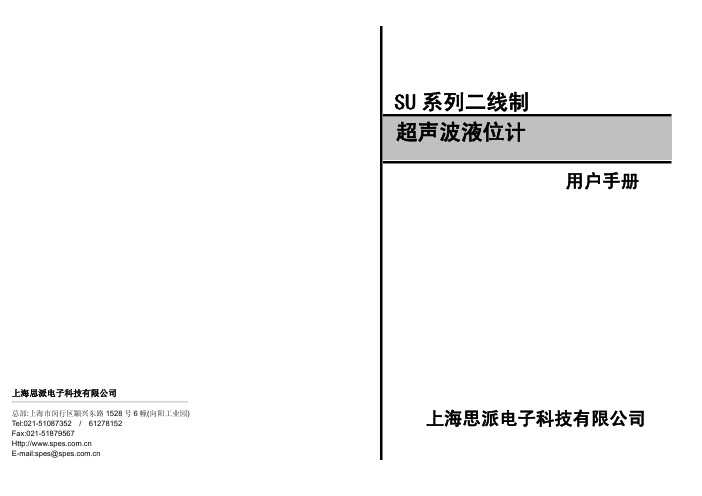
SU-2000用户手册(3月20日)
safe-fire火焰检测器用户手册

8.4
观测管组件 ................................................................................................................... 22
调试 ........................................................................................................................... 13 冷态调试....................................................................................................................... 13 热态调试....................................................................................................................... 14 热态调试-油火检调试 ................................................................................................... 14 热态调试-煤火检调试 ................................................................................................... 15
Maximizing Safety Through Reliability And High Performance.
SU超声波说明书
仪表安装完毕、上电后,液晶上会显示液位数值,而该数据往往与实际液位不符, 故需要液位标定。
液位标定步骤如下:按 Mode 键,输入密码,再按 OK 键进入参数设置菜单。P01 为液位标定菜单,按 OK 键进行 P01 液位标定,用 键(移位)和▲键(数字更改)将数
4.3.2 20mA 设置(P02) 在仪表正常工作时按 Mode 键进入参数设置菜单,按▲键选择 P02 菜单,第二行数字
即为 20mA 对应液位,按 OK 键进行设置。
4.3.3 显示模式设置(P03) P03 菜单可更改显示模式,共有 3 种显示模式可供选择: 1. 00 显示液位 2. 01 显示距离 3. 02 显示距离和气温 按▲键选择所需模式然后按 OK 键确认。
建议在液位仪周围加设防高、低温装置。
4、仪表调试
4.1 键盘说明
如上图所示,仪表的探头发波打到液位后反射回探头,探头接收到后计算发波到收 波的时间,得到测量距离 L,仪表安装高度 TH 减去测量距离 L 将得到当前液位 H。
仪表量程指仪表能够测量的距离,安装高度 TH 应小于量程。 仪表盲区指仪表在探头附近无法测量的区域,最高液位与探头间距应大于盲区,例 盲区为 0.3m,则液位与探头间距必须大于 0.3m。 探头发波是个扩散过程,即有方向角,安装的时候要注意,否则可能打到池壁的凸 起物或渠道边沿。
大于 120mm,长度 0.35m~0.50m,垂直安装,内壁光滑,罐上开孔应大于延伸管内 径。或者将管子通至罐底,管径大于 80mm,管底留孔保持延伸管内液面与罐内等高。
3
【Mode】:菜单键。按【Mode】出现密码界面,输入密码进入菜单,在设置时按【Mode】 取消设置,设置完毕后,按【Mode】键退出菜单。
PURElight 3 Way Mini用户手册说明书

Manuals+— User Manuals Simplified.MUSIC STORE PURElight 3 Way Mini User ManualHome » MUSIC STORE » MUSIC STORE PURElight 3 Way Mini User ManualPURE light 3 Way MiniUser ManualContents1 Important safetyinstructions2 Installation3 Guarantee4 Scope of delivery5 Intended use6 Setup7 Channel Mode8 Operation:9 Specifications10 Troubleshooting11 Cleaning12 Environmental protection13 Documents / Resources13.1 ReferencesImportant safety instructionsPlease read before connection!DANGER! (Electrical shock due to high voltages in the device)The housing must not be removed! There are no parts to be maintained in the device.Inside the unit there are components which are under high electrical voltage.Before each use, check the device for damage or the absence of components, protective devices or housing parts. If this is the case, the device must not be used!Leave maintenance and repair work to a qualified service workshop or contact your dealer. In the case of a malfunction of the device, operation must also be stopped immediately until the device has been repaired by a specialist!DANGER! (Electric shock due to short circuit)Modifications to the power cord or plug are prohibited. If the power cord is damaged, it must be replaced immediately with an original spare part from the manufacturer. Failure to do so may result in fire or death due to electric shock!DANGER! (For babies and children)Dispose of or store any packaging material properly! Packaging material must be kept out of the reach of babies and children due to the risk of suffocation.Ensure that children never use the appliance unattended! In addition, make sure that children do not remove (small) parts from the device, as they could suffocate by swallowing parts!WARNING! (High light intensity – eye injuries)A direct view into the light source is absolutely to be omitted!WARNING! (Epilepsy)Stroboscopic effects (flashes of light) can trigger seizures of epilepsy in some people. Accordingly sensitive people should be warned and should not be in the vicinity of such devices.Hint! (Fire hazard due to overheating)The maximum permissible ambient temperature of this device is 40°C.Ensure that the unit is placed in a well-ventilated location away from direct heat sources, naked flames, combustible materials, and liquids. A minimum distance of 1 m is required.Do not tape or cover the ventilation slots of the unit.Hint! (Operating conditions)Due to its structural characteristics, the device is designed for indoor operation (IP20).Never expose the device to rain, moisture or liquids as this may cause damage.Vibrations, dust or sunlight can also cause damage, avoid them!Hint! (Power supply)It is essential that you check that the device voltage matches your local mains voltage. It is highly recommended that you fuse your mains socket with a residual current circuit breaker (FI).If you do not use your device for a longer period of time or carry out maintenance work, disconnect the device from the mains in order to minimize danger. The same applies to storm conditions such as thunderstorms, floods, etc.Hint! (Error during data transmission)Never connect the DMX input or output to audio devices such as power amplifiers or mixing consoles!DMX cables enable trouble-free operation and the highest possible transmission reliability of signal data. Do not use microphone cables!Hint! (Condensation)To avoid condensation in the unit, the unit should adapt to the ambient temperature before commissioning.Hint! (Unwanted odours)A new product can sometimes lead to unwanted odours. This reaction is normal and disappears after a few minutes.Symbols on device and packaging:sure that the area below you is closed off.WARNING!Improper installation can cause considerable injury and damage!The installation of the device should always be carried out by experienced personnel and must be carried out in compliance with the mechanical and electrical safety regulations in your country.Scope of deliveryContent Quantity3-Way mini Moving Head1Power Cord1Manual1Intended useThe PURE light 3-Way Mini was designed for use as an electronic LED lighting effect. The device may only be used for this purpose and in accordance with the operating instructions. Other purposes as well as operation under other operating conditions are expressly not intended and can lead to damage to property or personal injury! No liability is assumed for damage resulting from improper use.It must be ensured that the device is operated exclusively by trained and competent users who are in full possession of their mental, physical and sensory abilities. The use of other persons is expressly only permitted at the request of a person responsible for their safety, who instructs or supervises the use.SetupAll connections of the device should be made before switching on. Only use high-quality cables that are as short as possible for the connections.Configuration oft he DMX connectorResistance 120 ohm // ¼ w between pin 2 (DMX-) and pin 3 (DMX+) oft he last fixture.Operating mode DMX:Connect the DMX input of your device to the DMX output of your DMX controller, your DMX software or the DMX output of a device already in your DMX line. Always use a DMX cable with a 110 Ohm resistor for this connection. Address the device according to your DMX configuration.The following table shows the respective DMX modes of the individual devices with the corresponding values and functions:Channel ModeChannel Value Function1000-255PAN 0° to infinite2000-255TILT 0 to 270°3000-127128-191192-255Offset Position Positive RotationReverse Rotation4000-255Master Dimmer (0 % to 100 %) 5000-255Red Dimmer (0 % to 100 %) 6000-255Green Dimmer (0 % to 100 %) 7000-255Blue Dimmer (0 % to 100 %) 8000-255White Dimmer (0 % to 100 %) 9000-255Stroboscope (Speed: slow to fast) 10000-255Auto Show11250-255ResetChannel ModeChannel Value Function1000-255PAN 0° to infinite2000-255PAN fine adjustment3000-255TILT 0 to 270°4000-255TILT fine adjustment5000-255PAN/TILT Speed (slow to fast)6000-127128-191192-255Offset PositionPositive Rotation Reverse Rotation7000-255Master Dimmer (0 % to 100 %)8000-255Red Dimmer (0 % to 100 %)9000-255Green Dimmer (0 % to 100 %)10000-255Blue Dimmer (0 % to 100 %)11000-255White Dimmer (0 % to 100 %)12000-255Stroboscope (Speed: slow to fast)13007-255Macros14250-255ResetStatic, Auto or Sound mode:The device contains automatic programs that run according to fixed schemes (Auto) or are recalled via the built-in microphone to match the music (Sound). The selection of the respective mode takes place via the menu directly on the device.If you connect several devices of the same type via DMX, they can be controlled simultaneously via the master device. To do this, set the desired function “Master” on the first device of the line, the other devices of the series must now be set as “Slave”. Now the first device of the line gives the function to all other devices and all devices run simultaneously.Operation:Start:Connect the device to the mains and wait a few seconds until it is ready for operation.Connections and controls:No.Designation No.Designation1Projector Head6DMX In (3-pole)2LED Lenses7DMX Out (3-pole)3Projector Arm8Power Twist Input4Menu Display9Power Twist Output5Menu ButtonsMenu:Navigation in the menu is via the four menu buttons below the display. Use the “Mode” button to activate the menu, navigate via the “Up” and “Down” buttons. A corresponding selection is confirmed with the “Enter” key.The menu structure in detail:MenüWert FunctionDoxes Address A001-A512Setting DMX addressChannel Set11CH/14CH DMX channel selection (11 or 14 channels)Show Mode DMX Mode Fast Mode Slow ModeSoud ModeDMX-Mode Show-Mode, fast Show-Mode, slow Sound controlSound Sense0-99Setting the microphone sensitivity for music controlPan Inverse OFFOnPANPAN-InverseTilt Inverse OFFOnTILTTILT-InverseDefault confirm Yes System reset Fixture Reset Yes System resetSpecificationsModel3-Way miniPower Supply AC110-240V, 50/60Hz Power Input100 WLEDs 6 x 15W (4in1)Colour Mixing RGBWRed – Green – Blue – WhiteBeam Angle6°Max. PAN Movement0° to infiniteMax. TILT Movement0° to 270°Dimmer0 – 100%, Linear DimmerStroboscope0 – 25 Flash/SecondOperating Modes DMX, Automatic Mode, Sound Control Mode, Master/Slave DMX Channels11 or 14Connections DMX-In/-Out (3-pole) Power Twist (In/-Out)Dimensions (L x W x H)330 x 280 x 260 mmWeight3,5 kgTroubleshootingThe following overview serves as an aid for quick troubleshooting. If you are unsure, contact the manufacturer, the dealer or the corresponding specialist personnel. Never open the device on your own!dispose of and recycle the packaging components after use properly.Disposal of packaging:Ensure that paper packaging, plastic materials, etc. are separately recycled. Observe the corresponding disposal instructions on the packaging.Disposal of batteries:Batteries do not belong in the garbage! Please keep batteries in accordance with the official collection points or disposal stations in accordance with the specifications.Disposal of your old device:Do not dispose of the device with household waste! This device is subject to the WEEE Directive (Waste ElectricalHersteller: MUSIC STORE professional GmbH,Istanbulstraße 22-26,51103 Köln, DeutschlandMS ID: LIG0016868-00007/2020Documents / ResourcesMUSIC STORE PURElight 3 Way Mini [pdf] User ManualPURElight 3 Way Mini, PURElight, 3 Way Mini, Way Mini, MiniReferencesMusic Store Online-Shop für Musikinstrumente | MUSIC STORE professional Music Store Online-Shop für Musikinstrumente | MUSIC STORE professionalManuals+,。
safefire SU2000

SU-2000火焰检测器 产品说明书目录1、产品概述1.1产品应用1.2技术指标2、安装2.1观测管检测火焰的安装2.2光纤型火检的安装2.3电气接线3、通讯设置3.1通讯接线3.2火检通讯软件3.3通讯地址4、操作界面4.1火检的操作界面4.2状态菜单4.3预编辑菜单4.4编辑菜单4.5自动调节菜单5、火检的参数设定5.1自动选择鉴别频率5.2手动设置火检参数6、维护和故障处理方法1、产品概述1.1产品应用SU-2000火焰检测器是一种安全、可靠的一体化智能型火检。
它用于检测包括煤粉、燃料油、等燃料的火焰。
适用于多燃料燃烧器及单燃料燃烧器的火焰检测。
SU-2000火检它不需要单独的放大器,由一个一体化检测头和信号处理器组成。
降低了安装成本,减少了故障点,也不再需要放大器柜,节约了专用电缆,方便了现场布线。
SU-2000火检是基于微处理器进行工作的,它采用了最先进的固态信号处理技术。
运用固态感光元件来检测火焰中的红外光光谱。
SU-2000火检里储存有4套配置设置文件,在火检运行时只有1套火检设置文件可被激活,可通过2个远程输入开关在4套文件之间切换。
当检测到目标燃烧器有火焰时,SU-2000会输出有火/无火接点信号和相应的火焰强度的模拟量信号,并输入BMS系统。
SU-2000带有独立的电子自检系统,自检间隔时间为每隔2分钟一次,如自检故障时,探头将输出故障报警信号。
SU-2000可通过专用火检软件与电脑进行通讯联网,单台电脑最多可连接128个探头,并可显示实时火焰状态及其它信息。
SU-2000火检探头外型如下:图1 SU-2000火检探头外型图1.2技术指标SU-2000火检探头既可以通过光纤检测火焰,也可以直接检测火焰。
详见如下技术规格标:传感器类型:固态响应范围:红外线1000nm峰值外壳材料:铸铝重量:0.9Kg防护等级:IP66环境温度:-40℃~65℃冷却风流量:20m3/Hr冷却风压力:6Kpa湿度:相对湿度0%—95%,非凝结通讯:RS232/RS485串形通迅,可接128个探头电缆组件:12芯,屏蔽、阻燃、带航空插头;电源:24VDC,+10%,-15%,直流:0.2A火焰继电器触点:N.O ,2A @240V AC(有火时闭合,无火时断开)故障继电器触点:N.O ,2A @240V AC(在故障及失电时断开)火焰信号强度:4-20mA 直流,有源输出,最大连接载荷:750欧姆有火响应时间:1到6秒可选无火响应时间:1到6秒可选2、安装2.1观测管检测火焰的安装火焰探头直接检测是将光信号通过观测管直接传到火焰探头的传感器上,火焰探头经过信号处理后,通过12芯电缆输出信号。
A9GT-BUSSU类型总线连接接口模块用户手册说明书

A9GT-BUSSU type Bus connection interface moduleUser’s ManualThank you for purchasing the MELSEC-GOT Series.To ensure correct use of this equipment, please carefully read this manual prior to use.MODEL A9GT-BUSSU-UMODEL1DM127CODEIB(NA)-0800076-C(0406)MEE Mitsubishi Graphic Operation Terminalz SAFETY PRECAUTIONS z(Always read before starting use)When using Mitsubishi equipment, thoroughly read this manual and the associated manuals introduced in the manual. Also pay careful attention to safety and handle the module properly.The instructions given this manual are concerned with this product. Refer to the User’s Manual of the CPU module in use for details on the safety instructions for the programmable logic controller system.These SAFETY PRECAUTIONS classify the safety precautions into two categories: "DANGER" and "CAUTION".Procedures which may lead to a dangerous conditionand cause death or serious injury if not carried outproperly.Procedures which may lead to a dangerous conditionand cause superficial to medium injury, or physicaldamage only, if not carried out properly.Depending on circumstances, procedures indicated by CAUTION may also be linked to serious results.In any case, it is important to follow the directions for usage.Store this manual in a safe place so that you can take it out and read it whenever necessary. Always forward it to the end user.[DESIGN PRECAUTIONS][INSTALLATION PRECAUTIONS][INSTALLATION PRECAUTIONS]CAUTIONz Use this module in the environment given in the general specifications of the GOT User's Manual.Not doing so can cause an electric shock, fire, malfunction or product damage or deterioration.z When installing this unit to the GOT, fit it to the connection interface of the GOT and tighten the mounting screws in the specified torque range.Undertightening can cause a drop, failure or malfunction.Overtightening can cause a drop, failure or malfunction due to GOT or screw damage.[WIRING PRECAUTIONS]CAUTIONz Insert and fit the bus connection cable into the connector of the module to be connected until it "clicks".After fitting, check for an unsung fit.Not doing so can cause a malfunction due to a connection fault.[STARTUP AND MAINTENANCE PRECAUTIONS]CAUTIONz Do not disassemble or modify any module.This will cause failure, malfunction, injuries, or fire.z Do not touch the conductive areas and electronic parts of this module directly.Doing so can cause a module malfunction or failure.z Always secure the cables connected to the module, e.g. run them in conduits or clamp them.Not doing so can cause module or cable damage due to dangling, moved or accidentally pulled cables or can cause a malfunction due to a cable contact fault.z Do not hold the cable part when unplugging any cable connected to the module.Doing so can cause module or cable damage or a malfunction due to a cable contact fault.z Before handling the unit, touch a grounded metal or similar object to discharge the static electricity from the human body.Failure to do so may cause the unit to fail or mulfunction.[DISPOSAL PRECAUTIONS]CAUTIONz Dispose of this product as industrial waste.ManualsThe following manuals are relevant to this product.Refer to the following list and order the required manuals. Detailed ManualsManual nameManual No. (Model code)A985GOT/A975GOT/A970GOT/A960GOT User’s Manual(Available as option)SH-4005 (1DM099)A950GOT/A951GOT/A953GOT/A956GOT User’s Manual(Available as option)SH-080018 (1DM103)Relevant ManualsFor relevant manual, refer to the PDF manual stored within the drawing software. Conformation to the EMC DirectiveA9GT-BUSSU conforms to the EMC Directive only when connected to the GOT (with CE logo printed on the rating plate) which conforms to the EMC Directive.For details of Conformation to the EMC Directive, refer to the using GOT User's Manual (Hardware).1. OverviewThis User's Manual describes the A9GT-BUSSU type Bus connection interface module (hereinafter, A9GT-BUSSU).The A9GT-BUSSU is mounted on the A985GOT(-V)/A975GOT/A970GOT/A960GOT/ A956GOT/A956WGOT (hereinafter, GOT) to PLC system via a bus.The A9GT-BUSSU is a dedicated module for the GOT-A900 Series.The A9GT-BUSS is used with the following system:(1) One GOT is connected to one PLC CPU; or(2) Used with the last GOT when two or more GOTs are connected to one PLC CPU.(Since this module has one interface.)GOT BackMain base unit/extension base unitBus connectorconversion module(A7GT-CNB)A9GT-BUSSUWith the A9GT-BUSSU, the dimensions of the cable that protrudes from the bottom of the GOT are smaller than the A9GT-BUSS/A9GT-BUS2S type bus connection interface board (hereinafter, bus connection board) used with the conventional bus connection.In case of A97 GOTType A BBus connection board40(1.57)85(3.35)A9GT-BUSSU69(2.72)15(0.59)In case of A985GOT/A960GOTType A BBus connection board43(1.69)100(3.9)A9GT-BUSSU72(2.83)30(1.18)Bus connection board used A9GT-BUSSUusedAB ABUnit: mm (inch)The applicable CPU and system configuration is the same as the conventional bus connection board.Refer to the GOT-A900 Series User's Manual (Connection System Manual) for the configuration of the bus connection system.The A9GT-BUSSU cannot be used together with the bus connection board.After opening the container, check that the following products are present.Description QuantityA9GT-BUSSU 12. Specification Item SpecificationI/O occupied points 32 points (I/O assignment: Special 32 points)CPU 5VDC29.0 (220*1)Internal consumed current [mA]*1GOT 5VDC Included in GOTWeight [kg](lb)0.17 (0.37)*1: Supplied from the GOT side when GOT power is on.Supplied from the PC system side when GOT power is off.*2: State with PLC CPU power ON and GOT power OFF. 3. Name of the Parts and Outline Dimension Drawing(1)(4)(2)(4)(7)(6)(3)(5)5(0.2)34(1.34)149(5.87)99(3.9)Unit: mm (inch) Description (1)Extension number setting switch Used to set the extension number for GOT assignment.(Factory setting: 0)<Setting range> 1 to 7 : Extension number 8, 9, 0: Must not be used.(2)I/O slot setting switch Used to set the I/O slot number for GOT assignment.(Factory setting: 0)<Setting range> 0 to 7: I/O slot number 8, 9 : Must not be used.(3)Bus connection cable connecting interface Interface for connection of the bus connection cable (IN side)(4)mounting screw Screw for mounting to the GOT (M3 screw)(5)Connector Connector for connection to the GOT (6)Caution plate -(7)Rating plate -4. Installation Procedure(1) Fit the communication module securingfixtures in the GOT main unit.(2) Mount the A9GT-BUSSU on the GOTinterface.(3) Tighten and fix the mounting screws (3pcs.) of the A9GT-BUSSU in thespecified torque range.WarrantyMitsubishi will not be held liable for damage caused by factors found not to be the cause of Mitsubishi; machine damage or lost profits caused by faults in the Mitsubishi products;damage, secondary damage, accident compensation caused by special factors unpredictable by Mitsubishi; damages to products other than Mitsubishi products; and to other duties.For safe usey This product has been manufactured as a general-purpose part for general industries,and has not been designed or manufactured to be incorporated in a device or system used in purposes related to human life.y Before using the product for special purposes such as nuclear power, electric power,aerospace, medicine or passenger movement vehicles, consult with Mitsubishi.y This product has been manufactured under strict quality control. However, when installing the product where major accidents or losses could occur if the product fails, install appropriate backup or failsafe functions in the system.U.S.A Mitsubishi Electric Automation Inc.500 Corporate Woods Parkway VernonHills, IL 60061Tel : +1-847-478-2100Brazil MELCO-TEC Rep. Com.e AssessoriaTecnica Ltda.AV. Paulista 1471, Conj. 308,Sao Paulo City, Sao Paulo State,BrazilTel : +55-11-283-2423Germany Mitsubishi Electric Europe B.V. GermanBranchGothaer Strasse 8 D-40880 Ratingen,GERMANYTel : +49-2102-486-0U.K Mitsubishi Electric Europe B.V. UKBranchTravellers Lane, Hatfield, Herts., AL108XB,UKTel : +44-1707-276100Italy Mitsubishi Electric Europe B.V. ItalianBranchCentro Dir. Colleoni, Pal. Perseo-Ingr.2Via Paracelso 12, 20041 Agrate B.,Milano, ItalyTel : +39-039-6053344Spain Mitsubishi Electric Europe B.V. SpanishBranchCarretera de Rubi 76-8008190 - Sant Cugat del Valles,Barcelona, SpainTel : +34-93-565-3131France Mitsubishi Electric Europe B.V. FrenchBranch25 Boulevard des Bouvets, F-92741Nanterre Cedex, FranceTEL: +33-1-5568-5568South Africa Circuit Breaker Industries LTD.Tripswitch Drive, Elandsfontein Gauteng,South AfricaTel : +27-11-928-2000Hong Kong Ryoden Automation Ltd. 10th Floor, Manulife Tower, 169 Electric Road, North Point, HongKong Tel : +852-2887-8870China Ryoden Automation Shanghai Ltd. 3F Block5 Building Automation Instrumentation Plaza 103 Cao Bao Rd. Shanghai 200233 China Tel : +86-21-6475-3228Taiwan Setsuyo Enterprise Co., Ltd. 6F., No.105 Wu-Kung 3rd.RD, Wu-Ku Hsiang, Taipei Hsine, Taiwan Tel : +886-2-2299-2499Korea HAN NEUNG TECHNO CO.,LTD. 1F Dong Seo Game Channel Bldg., 660-11, Deungchon-dong Kangsec-ku, Seoul, Korea Tel : +82-2-3660-9552Singapore Mitsubishi Electric Asia Pte, Ltd. 307 ALEXANDRA ROAD #05-01/02, MITSUBISHI ELECTRIC BUILDING SINGAPORE 159943 Tel : +65-6473-2308Thailand F. A. Tech Co.,Ltd. 898/28,29,30 S.V.City Building,Office Tower 2,Floor 17-18 Rama 3 Road, Bangkpongpang, Yannawa, Bangkok 10120 Tel : +66-2-682-6522Indonesia P.T. Autoteknindo SUMBER MAKMUR Jl. Muara Karang Selatan Block A Utara No.1 Kav. No.11 Kawasan Industri/ Pergudangan Jakarta - Utara 14440 Tel : +62-21-663-0833India Messung Systems Put,Ltd. Electronic Sadan NO:111 Unit No15, M.I.D.C BHOSARI,PUNE-411026 Tel : +91-20-712-2807Australia Mitsubishi Electric Australia Pty. Ltd. 348 Victoria Road, PostalBag, No 2, Rydalmere, N.S.W 2116, Australia Tel : +61-2-9684-7777Country/Region Sales office/Tel When exported from Japan, this manual does not require application to the Ministryof Economy, Trade and Industry for service transaction permission.Specifications subject to change without notice.Printed in Japan on recycled paper.HEAD OFFICE : 1-8-12, OFFICE TOWER Z 14F HARUMI CHUO-KU 104-6212, JAPAN NAGOYA WORKS : 1-14, YADA-MINAMI 5-CHOME, HIGASHI-KU, NAGOYA, JAPANCountry/Region Sales office/Tel。
Extech 382252 物理地球电阻测试仪用户手册说明书
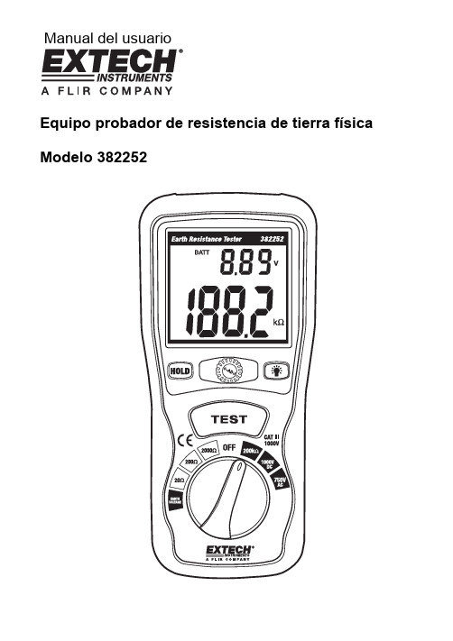
Manual del usuarioEquipo probador de resistencia de tierra física Modelo 382252IntroducciónAgradecemos su compra del equipo probador de resistencia de tierra física modelo 382252 de Extech. Este dispositivo puede medir la resistencia de tierra física (en 3 escalas); Voltaje de tierra;Resistencia (hasta 200kΩ); voltaje CA y CD. Este dispositivo fue diseñado para cumplir con las normas de seguridad EN61010-1. El uso cuidadoso de este medidor le proveerá muchos años de servicio confiable.SeguridadPor favor lea cuidadosamente la siguiente información de seguridad antes de intentar operar el medidor y úselo sólo como se especifica en este manual.Información de seguridad ambiental•No use el medidor en el exterior cuando exista la probabilidad de precipitación•Instalación Categoría III•Grado de contaminación 2•Altitud: 2000 metros máx.•Condiciones ambientales: 0 a 40o C (32 a 104o F); HR: 80% máx.•Observe las siguientes señales internacionales de advertencia y seguridadSeñales de seguridadPrecaución: Consulte este manual antes de usar el medidorVoltajes peligrososEl medidor está totalmente protegido por aislante doble o reforzado Organizaciones que establecen las reglas y lineamientos para conexiones a tierra apropiadas •El Código Eléctrico Nacional (NEC)•Underwriters Laboratories (UL)•Asociación Nacional de Protección Contra Incendio (NFPA)•American National Standards Institute (ANSI)•Occupational Safety Health Administration (OSHA)•Telecommunications Industry Standard (TIA)Descripción del medidor1. Indicador digital – Ver la descripción de la pantalla2. Retención(HOLD) – Congela la medida en la pantalla3. 0 ADJ- Ajusta el valor cero en pantalla4. Tecla Retroiluminación – activa la retroiluminación5. TeclaTEST – Activa la prueba de resistencia de tierra y la prueba de voltaje de tierra6. Interruptor selector de función – Selecciona la escala yfunciónVista superior1. EntradaVΩ/C2. EntradaP3. EntradaCOM/EDescripción de la pantalla1. Icono de estado de la prueba2. Indicador de carga de la batería -3. Indicador de voltaje de la unidad4. Icono de señal audible5. IndicadorunidadesΩ/kΩ6. Valor de la medición7. Indicadores de voltaje CA/CD8. Icono de batería débil9. Icono de RETENCIÓN (HOLD)345 7896123OperaciónAjuste a 01. Conecte los cables de prueba en el medidor como se indica a continuación:a. Cable verde a la terminal 'E'b. Cable amarillo a la terminal 'P'c. Cable rojo a la terminal 'C'2. Fije el selector de función en la escala de corriente deseada.3. Haga corto con los 3 cables de prueba.4. Presione la tecla TEST.5. Use la perilla 0 y ajuste la lectura en pantalla a 0Ω.6. Presione la tecla TEST de nuevo para terminar el proceso de ajuste a 0.Diagrama de conexión de prueba:3822521. Medidor2. Cable verde de prueba3. Cable amarillo de prueba4. Cable rojo de prueba5. Tierraexistente6. Varilla auxiliar de tierra P17. Varilla auxiliar de tierra C1Preparación y configuración de la prueba1. Conecte los cables de prueba en el medidor (1) como se indica a continuación:•Cable verde (2) a la terminal 'E'•Cable amarillo (3) a la terminal 'P'•Cable rojo (4) a la terminal 'C'2. Encaje las varillas auxiliares de tierra P1 (6) y C1 (7) en el suelo. Alinee las varillasequidistantes a la conexión de tierra física existente y en línea recta como se muestra en el diagrama anterior. Para evitar imprecisiones, no coloque las varillas auxiliares próximas a la varilla de tierra.3. Conecte las abrazaderas de los cables de prueba a las varillas auxiliares y la varilla de tierraexistente, como se indica en el diagrama:•Cable verde (2) a la tierra existente (5)•Cable amarillo (3) a la varilla de tierra P1 (6)•Cable rojo (4) a la varilla de tierra C1 (7)Prueba de voltaje de tierra1. Fije el selector de función en la posición VOLTAJE.2. Confirme que la medida de voltaje sea menor a 10V CA; de lo contrario no se podrán tomarmedidas precisas de tierra. Si hay voltaje presente (más de 10V CA), debe encontrar y corregir la fuente del voltaje antes de continuar con la prueba.3. Presione la tecla TEST para terminar la pruebaPrueba de resistencia tierra1. Ajuste el selector de función a la escala de resistencia deseada.2. Presione la tecla TEST (prueba). . El icono " " icono centelleará y sonará la señal audible.3. Tome nota de la lectura indicada.4. Si detecta alta resistencia, anote el valor y tome los pasos apropiados para corregir la conexióna tierra si es necesario.5. Presione la tecla TEST para terminar la prueba.6. Lecturas de “1”…Ω son típicas cuando los cables de prueba no están conectados al medidor. Función de retención (HOLD)La función de retención congela la última lectura de medición en la LCD.1. Presione la tecla HOLD para retener la lectura en la LCD2. Presione la tecla HOLD de nuevo para salir de la función retención.3. La función retención no guarda el dato de la medición si apaga el medidor.Retroiluminación““para encender la retroiluminación.1. Presione2. La retroiluminación se apagará después de 15 segundos aproximadamente.Medición de resistencia 200kΩ1. Conecte el cable rojo de prueba al conector V y el cable negro de prueba a la terminal Ω COM.2. Ajuste el selector de función a la posición Ω 200k.3. Conecte las sondas de prueba al circuito o componente a prueba.4. Tome nota del valor de resistencia indicado.Medición de voltaje AC1. Conecte el cable rojo de prueba al conector Ω V y el cable negro de prueba a la terminal COM.2. Ajuste el selector de función a la posición 750V AC.3. Conecte las sondas de prueba al circuito a prueba.4. Tome nota del valor de voltaje indicado.Medición de voltaje DC1. Conecte el cable rojo de prueba al conector ΩV y el cable negro de prueba a la terminal COM.2. Ajuste el selector de función a la posición 1000V DC3. Conecte las sondas de prueba al circuito a prueba.4. Tome nota del valor de voltaje indicado.MantenimientoBatería ReemplazoCuando el icono de batería débil '' aparece en la LCD, deberá cambiarlas baterías del medidor1. Apague el medidor y desconecte los cables de prueba.2. Retire el soporte inclinado de atrás del medidor.3. Quite los 4 tornillos del compartimiento de la batería con un destornilladorcabeza Phillips.4. Quite la tapa del compartimiento de la batería y reemplace las seis baterías'AA' de 1.5V.5. Coloque la tapa del compartimiento y asegure con los tornillos.6. Reinstale el soporte inclinado.Usted, como usuario final, está legalmente obligado (Reglamento de baterías) a regresarCumpla las estipulaciones legales vigentes respecto al desecho del dispositivo al final de su vida útil.Limpieza y almacenamientoPeriódicamente limpie la caja con un paño húmedo y detergente suave; no use abrasivos osolventes. Si el medidor no será usado durante periodos mayores a 60 días, retire la batería y almacénelos por separado.EspecificacionesEspecificaciones generalesMedidas resistencia de tierra física (en 3 escalas), voltaje de tierra,voltaje CA hasta 750V y voltaje CD hasta 1000VdoblePantalla LCDTiempo de muestreo 2.5 veces por segundoLargo cables de prueba Cable rojo: 15m (50'), Amarillo: 10m (33'), Verde: 5m (16')Indicación de sobre escala Indica '1' como dígito más relevante.Fuente de energía seis baterías 'AA' de 1.5V (incluidas)Indicación de batería débil LCD indica iconoApagado automático Después de aproximadamente 15minutos de usoSeguridad EN-61010-1 Categoría IIIPeso 700g (24.7 oz.) con bateríasDimensiones 200 X 92 X 50 mm (7.9 X 3.62 X 2")Accesorios suministrados La Prueba de Multímetro conduce (2), la prueba de Tierra de la Tierraconduce (3),barras de la tierra auxiliares (2), seis baterías 'AA', y casode transporteCondiciones de operación 0ºC a 40ºC (32ºF a 104ºF), con < 80% HRCondiciones de almacenamiento -10ºC a 60ºC (14ºF a 140ºF), con < 70% HREspecificaciones de Medida MediciónEscalaResoluciónPrecisión20Ω0.01Ω ± (2% lectura + 10 dígitos) 200Ω 0.1Ω Resistencia de tierra física2000Ω 1Ω ± (2% lectura + 3 dígitos)Voltaje de tierra Frecuencia: 40 a500Hz 0 a 200VAC0.1V ± (3% lectura +3 dígitos) 0 a 200k Ω0.1k Ω± (1% lectura +2 dígitos)ResistenciaProtección de sobre carga: 250 Vrms0 a 750V 1V ± (1.2% lectura +10 dígitos)Voltaje CA 40 Hz a 400Hz Protección de sobre carga: 750 Vrms, Impedancia de entrada: 10M Ω 0 a 1000V1V± (0.8% lectura +3 dígitos)Voltaje CD Protección de sobre carga: 1000 Vrms, Impedancia de entrada: 10M ΩCopyright © 2012 Extech Instruments Corporation (una empresa FLIR)Reservados todos los derechos, incluyendo el derecho de reproducción total o parcial en cualquier medio.。
M CONFORT HI-2000 短波红外热辐射器用户手册说明书
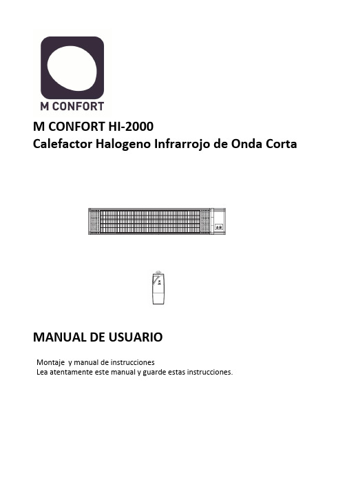
M CONFORT HI-2000Calefactor Halogeno Infrarrojo de Onda CortaMANUAL DE USUARIOMontaje y manual de instruccionesLea atentamente este manual y guarde estas instrucciones.IntroducciónEl calentador de infrarrojos contiene una lámpara de calefacción por infrarrojos y un reflector que proporciona una distribución uniforme del calor.El calentador infrarrojo ahorra 30% -40% de electricidad en comparación con los calentadores tradicionales para terrazas.La temperatura máxima del producto es de 120 gradosAdvertenciaEl calentador de infrarrojos está diseñado para un funcionamiento seguro. Sin embargo, la instalación, mantenimiento y operación del calentador puede ser peligroso para un operador descuidado. Para su seguridad y la seguridad de los demás, por favor, lea las instrucciones de este manual de usuario y siga estas prácticas de seguridad a fin de evitar daños o lesiones.1. Compruebe que el voltaje de la red corresponde a la clasificación del aparato antes de operar.2. No toque las superficies calientes.3. Coloque sobre una superficie plana y estable en el caso de utilizar un trípode.4. Se puede utilizar tanto en sitios cerrados como al aire libre con cuidado de mantener el aparato protegido de la intemperie. Solo se debe utilizar en lugares secos.5. No utilice cerca o en las inmediaciones de la ducha/bañera o en una piscina Solo se debe utilizar en superficies secas.6. Desenchufar de la toma de corriente cuando no esté en funcionamiento.7. Para protegerse contra descargas eléctricas, no sumerja el cable o el enchufe en agua o cualquier otro líquido.8. El uso de accesorios no recomendados por el fabricante del aparato, puede causar graves lesiones.9. Procure tener una distancia adecuada alrededor del calentador para su refrigeración y la ventilación y así evitar cualquier peligro.10. Nunca coloque objetos inflamables o ropa en la parte superior o cerca del calentador.11. No utilice este aparato en las proximidades o cerca de líquidos que sean inflamables o materiales inflamables para así evitar un peligro de incendio. No poner cerca de cortinas, muebles, estanterías, etc.12. No utilice este aparato para otra cosa que no sea su uso previsto.13. No ponga los dedos u objetos extraños en la rejilla mientras esté en funcionamiento.14. No deje el aparato sin vigilancia cuando está en uso.15. Para quitar el enchufe del tomacorriente, no tire del cable. Sujete la clavija firmemente y tire de ella con fuerza.16. No se acepta responsabilidad por cualquier daño causado por el incumplimiento de estas instrucciones o cualquier otro uso indebido del aparato.17. Este aparato es sólo para uso doméstico.18. Este aparato no está diseñado para ser utilizado por personas (incluidos niños) con capacidades físicas, sensoriales o mentales reducidas o falta de experiencia y conocimiento, a menos que una persona responsable de su seguridad les supervise o que estén lo suficientemente instruidos acerca del uso del aparato. Los niños deben ser supervisados para asegurarse de que no jueguen con el aparato.19. Si el cable está dañado de alguna manera, debe ser reemplazado por el fabricante o su agente de servicio o una persona calificada para evitar un peligro.20. Para evitar el sobrecalentamiento de este aparato, mantenga las entradas y salidas de aire limpio y libre de cualquier obstrucción. Revise todas las entradas y salidas de vez en cuando para asegurarse de que esté libre de cualquier suciedad o polvo. NO CUBRIR/TAPAR21. Este aparato no está diseñado para ser operado por medio de un temporizador externo o un sistema de control remoto externo.22. La exposición continua a la radiación infrarroja de alta intensidad en las proximidades podría ser perjudicial para los ojos o la piel. Aunque el tubo de calefacción por infrarrojos no emite radiación electromagnética ultravioleta, puede causar quemaduras si se esta en contacto con el tubo de la calefacción o está operando a una alta intensidad.Debido a la brillante luz que emiten los tubos de calefacción por infrarrojos , se recomienda que los ojos estén protegidos de esta luz, no es aconsejable fijar la vista prolongadamente, si lo va hacer proteja sus ojos con los medios adecuados, Gafas oscuras o de sol.23. Este calentador no está equipado con un dispositivo para controlar la temperatura ambiental. No utilice este calentador en pequeñas habitaciones que están ocupadas por personas que no tengan movilidad para salir de la habitación por su cuenta, a menos que haya una supervisión constante.24. Las partes del calentador pueden superar los 200 ºC. Tocar el tubo de la calefacción, reflector, o las partes metalicas cerca del tubo del calentador , puede causar quemaduras severas25. Nunca coloque las manos debajo de la calefacción. Siempre procure desenchufar el calentador y que se enfríe por lo menos 10 minutos antes de tocar el tubo de la calefacción o partes adyacentes26. Observe que se cumplan todos los códigos eléctricos locales y nacionales y un sistema de tierra eléctrica segura este instalado antes de intentar poner en funcionamiento el calentador. Consulte los procedimientos para una instalación adecuada.27. Este producto contiene materiales reciclables. No deseche este producto como desecho municipal sin clasificar. Por favor contacte a su municipio local para el punto de recogida más cercano.28. Obedezca las mismas normas de seguridad contra incendios que usted observa cuando se trabaja con placas calientes, calentadores infrarrojos de alta intensidad, propano o sopletes de acetileno, soldadores y otros equipos de altas temperaturas.29. Sepa donde se encuentra el extintor más cercano y cómo usarlo.30. Sepa cómo apagar el fuego de todo tipo de material cerca del calentador de infrarrojos.INSTRUCCIONES DE MONTAJEMontado en pared1. Hacer agujeros en la pared donde el calentador se va a montar con un lápiz. Utilice una regla o nivelador para asegurarse de que el calentador esta recto. (Figura 1)2. Taladre los agujeros con una broca de 5 mm. (Figura 1)3. Introduzca el punto final del perno de anclaje a la pared. Clave el anclaje con un martillo hasta que el perno esté al ras con la pared. (Figura 2)4. Utilice una llave inglesa para fijar el soporte de montaje a la pared. (Figura 3)5. Montar al soporte de montaje con el tornillo apretado. (Figura 4)6. Apriete la parte trasera del calentador en el soporte con la tuerca de montaje y con la llave. (Figura 5)El calentador se debe instalar al menos 1,8 m por encima del sueloFUNCIÓN / OPERACIÓNLa tecnología de calefacción por rayos infrarrojos replica los rayos saludables del sol, calentando directamente el objeto o las personas en frente del calentador. A medida quela temperatura de la superficie calentada se eleva, el efecto de calentamiento se siente en todo el ambiente. Estos aparatos son ideales para utilizar en espacios abiertos y en zonas que sean amplias, son equipos que ahorran energía, son seguros y producen un calor sano.No dejan olor, o productos químicos ni humo.1. Conecte la unidad a una toma de corriente. Asegúrese de que la fuente de alimentacióny el equipo tienen el mismo voltaje.2. Pulse el botón de encendido en el lado derecho del calentador3. El indicador luminoso LED muestra el calentador está de espera. (Standby)4. Botón HEAT (ON / OFF) en el panel de control para encender el calentador póngalo en ON. Para apagar el calentador, presione el botón a la posición OFFInspeccione periódicamente su calentador y limpie el equipo de polvo o suciedad periódicamente. De este modo se asegurará de que los equipos funcionan con seguridad. INSTRUCCIONES DE LIMPIEZALa limpieza regular y cuidadosa ayuda a que su calentador de infrarrojos funcione de manera eficiente durante muchos años y sin problemas. Para limpiar la estufa, siga estos pasos:1. Desconecte el cable para su seguridad antes de limpiar el aparato.2. Asegúrese de que el calentador esté frío antes de continuar3. Para mantener el calentador limpio por su parte exterior se puede limpiar con un paño suave y húmedo. Usted puede usar un detergente suave, si fuera necesario. Después de la limpieza, seque la unidad con un paño suave. (PRECAUCIÓN: No deje que los líquidos entran en el calentador)4. No utilice alcohol, gasolina, polvos abrasivos, cera para muebles o cepillos ásperos para limpiar el calentador. Esto puede causar daño y/ o deterioro a la superficie del calentador.5. NO sumerja el calentador en agua6. No trate de desmontar el equipo. Esta tarea queda reservada a los servicios técnicos oficiales.7. Espere hasta que el calentador esté completamente seco antes de usar o de guardar.8. En caso de duda consulte con el fabricanteAlmacenamiento: Almacene el calentador en un lugar fresco y seco, libre de humedades. Cuando no esté en uso, para evitar que el polvo y la suciedad se acumulen utilice su caja de embalaje para guardar su calentador.C/ Catarroja, 1. Oficina 20646940 Manises (Valencia) EspañaAtencion al cliente: +34 961536720SAT:****************。
SU-2000用户手册(3月20日)

SU-2000火焰检测器用户手册目录1 介绍 (1)1.1 产品开箱确认 (1)1.2 声明 (1)2 描述 (2)3 主要部件 (3)3.1 挠性光纤组件 (6)3.2 观测管组件 (6)3.3 安装管组件 (7)3.4 冷却风软管 (7)3.5 手动球阀 (7)3.6 火检探头 (7)3.7 电缆组件 (8)3.8 电源组件 (8)3.9 联网软件 (8)4 安装 (9)4.1 观测管组件的安装 (9)4.2 挠性光纤组件的安装 (10)4.2.1 外导管组件的安装 (10)4.2.2 内导管组件的安装 (11)4.3 安装管组件的安装 (11)4.4 冷却风软管的安装 (11)4.5 火检探头的安装 (11)4.6 电源组件的安装 (11)4.7 电缆组件就地接线盒的安装 (11)4.8 电气连接 (12)5 调试 (13)5.1 冷态调试 (13)5.2 热态调试 (14)5.2.1 热态调试-油火检调试 (14)5.2.2 热态调试-煤火检调试 (15)6 操作 (17)6.1 自动选择鉴别频率 (17)6.2 手动选择鉴别频率 (18)7 常见问题处理 (19)8 维护 (21)8.1 光纤 (21)8.2 内导管组件 (22)8.3 外导管组件 (22)8.4 观测管组件 (22)8.5 冷却风软管 (22)8.6 火检探头 (23)8.7 电缆组件 (23)9 仓储 (24)10 产品返修 (25)11 备件采购 (25)12 表单模板 (26)12.1 RMA维修联络单模板 (26)12.2 备件询价单模板 (27)其他附图∙挠性光纤组件∙观测管组件∙电源分配回路图∙火检系统接线原理图∙电源柜外形尺寸示意图∙就地接线盒及接线示意图∙火检系统联网图1 介绍SU-2000火焰检测器作为锅炉安全检测设备,被广泛运用于电站、石化、冶金等行业的单燃烧器或多燃烧器锅炉中,在锅炉启动、运行的各个阶段,对燃烧器火焰进行准确检测,能够有效地预防燃料送入炉膛而未被点燃时可能导致炉膛爆炸的潜在危险,为锅炉安全稳定运行提供保护。
- 1、下载文档前请自行甄别文档内容的完整性,平台不提供额外的编辑、内容补充、找答案等附加服务。
- 2、"仅部分预览"的文档,不可在线预览部分如存在完整性等问题,可反馈申请退款(可完整预览的文档不适用该条件!)。
- 3、如文档侵犯您的权益,请联系客服反馈,我们会尽快为您处理(人工客服工作时间:9:00-18:30)。
SU-2000火焰检测器用户手册目录1 介绍 (1)1.1 产品开箱确认 (1)1.2 声明 (1)2 描述 (2)3 主要部件 (3)3.1 挠性光纤组件 (6)3.2 观测管组件 (6)3.3 安装管组件 (7)3.4 冷却风软管 (7)3.5 手动球阀 (7)3.6 火检探头 (7)3.7 电缆组件 (8)3.8 电源组件 (8)3.9 联网软件 (8)4 安装 (9)4.1 观测管组件的安装 (9)4.2 挠性光纤组件的安装 (10)4.2.1 外导管组件的安装 (10)4.2.2 内导管组件的安装 (11)4.3 安装管组件的安装 (11)4.4 冷却风软管的安装 (11)4.5 火检探头的安装 (11)4.6 电源组件的安装 (11)4.7 电缆组件就地接线盒的安装 (11)4.8 电气连接 (12)5 调试 (13)5.1 冷态调试 (13)5.2 热态调试 (14)5.2.1 热态调试-油火检调试 (14)5.2.2 热态调试-煤火检调试 (15)6 操作 (17)6.1 自动选择鉴别频率 (17)6.2 手动选择鉴别频率 (18)7 常见问题处理 (19)8 维护 (21)8.1 光纤 (21)8.2 内导管组件 (22)8.3 外导管组件 (22)8.4 观测管组件 (22)8.5 冷却风软管 (22)8.6 火检探头 (23)8.7 电缆组件 (23)9 仓储 (24)10 产品返修 (25)11 备件采购 (25)12 表单模板 (26)12.1 RMA维修联络单模板 (26)12.2 备件询价单模板 (27)其他附图∙挠性光纤组件∙观测管组件∙电源分配回路图∙火检系统接线原理图∙电源柜外形尺寸示意图∙就地接线盒及接线示意图∙火检系统联网图1 介绍SU-2000火焰检测器作为锅炉安全检测设备,被广泛运用于电站、石化、冶金等行业的单燃烧器或多燃烧器锅炉中,在锅炉启动、运行的各个阶段,对燃烧器火焰进行准确检测,能够有效地预防燃料送入炉膛而未被点燃时可能导致炉膛爆炸的潜在危险,为锅炉安全稳定运行提供保护。
请在安装或使用产品前,仔细阅读本用户手册,这将有助于您更好地了解和使用产品。
1.1 产品开箱确认开箱前,请确认包装箱外观完好无损,装箱清单信息清晰、完整。
开箱时,请根据装箱清单所列之信息,逐一核对、清点产品的数量,并确认产品外观完好、无损坏。
如有任何产品遗失或损坏,请与Safe-Fire公司或者当地合作伙伴联系。
1.2 声明本用户手册不包含任何保修声明。
只有通过相关培训的人员才可从事本产品的安装、使用和维护。
2 描述SU-20000火焰检测器分光纤型和非光纤型两种。
光纤型火焰检测器包括桡性光纤组件、安装管、冷却风管、SU-2000IR和SU-2000UV火检探头、电缆组件等组成。
非光纤型火焰检测器包括观测管组件、安装管、冷却风管、SU-2000IR和SU-2000UV火检探头、电缆组件等组成。
SU-2000火焰检测器:∙是一种安全、可靠的智能型火焰检测器。
∙适用于检测包括煤粉、燃料油、燃料气等燃料的火焰。
∙适用于多燃烧器和单燃烧器锅炉的火焰检测。
∙不需要配臵火检放大器,结构紧凑。
∙可应用于锅炉现场环境较高的要求。
3 主要部件SU-2000火焰检测器主要包含以下部件:∙火检探头;∙挠性光纤组件,包括外导管组件、内导管组件、光导纤维;∙观测管组件,包括观测管、万向接头、Y型三通、隔热管;∙安装管组件;∙1”冷却风软管;∙电缆组件,包括接线盒;∙电源柜;∙选装件,包括电脑、火检联网软件、联网电缆。
火焰检测器典型的配臵如下所示:图1 典型配臵图(光纤型),图2 典型配臵图(非光纤型)3.1 挠性光纤组件挠性光纤组件包括前端头组件、外导管组件、内导管组件、光纤等部件。
3.1.1 前端头组件∙保护光纤导管,将整个内外导管在燃烧喷口处后移,隔离热传导,减少热辐射。
∙在安装挠性光纤组件时,请确认挠性光纤组件长度与风箱尺寸相匹配。
∙前端头组件,安装于燃烧器喷口指定位臵。
∙需根据图纸采用不锈钢焊条牢固焊接在燃烧器喷口指定位臵。
3.1.2 外导管组件∙内部通冷却风,保护内导管与光纤。
∙固定在二次风箱内,请确认挠性光纤组件长度与风箱尺寸相匹配。
∙前端与前端头组件螺纹联接,焊接在二次风箱的喷口上,后端固定在安装管组件内。
3.1.3 内导管组件∙内部通冷却风,保护光纤。
∙安装在外导管组件中,请确认内导管组件长度与外导管组件尺寸相匹配。
3.1.4 光纤∙用于传导燃烧器火焰信号。
∙安装在内导管组件中,请确认光纤长度与内导管组件尺寸相匹配。
3.2 观测管组件观测管组件用于非光纤型火焰检测器的应用。
它包括观测管、Y型三通、隔热管等部件。
3.2.1 观测管∙固定焊接在燃烧器外壁上,将燃烧器的火焰信号从炉内传出。
3.2.2 Y型管∙是观测管与冷却风管的连接接口。
3.2.3 隔热管∙阻挡热量从观测管传递到火检探头3.2.4 孔板(如有)∙限制目标火焰区域的视角范围。
∙用孔板固定圈来固定于万向接头球内的。
3.2.5 石英视窗(如有)∙可防止炉膛飞灰污染火检探头的透镜。
3.3 安装管组件∙固定焊接在燃烧器外壁上,支撑挠性光纤组件。
∙密封锅炉风箱,防止二次风外漏。
3.4 冷却风管软管∙用于连接火检挠性光纤组件/观测管与冷却风母管。
∙输送火检冷却风。
3.5 手动球阀∙接口尺寸与冷却风软管尺寸相配。
∙维护时,切断冷却风气源。
3.6 火检探头∙是一种安全、可靠的一体化智能型火检。
用于检测包括煤粉、燃料油、燃料气等燃料的火焰。
∙适用于多燃烧器及单燃烧器锅炉的火焰检测。
∙不需要单独的放大器,由一个一体化检测头和信号处理器组成,减少了故障点。
∙采用DSP微处理器技术。
∙带有独立的电子自检系统,自检间隔时间为每隔2分钟一次。
3.7 电缆组件∙由一根12芯带航空插头的电缆组件。
∙连接火检探头至就地接线盒的信号处理,电缆一端接快装接头,另一端连接线盒。
∙安装在一个有接地线的韧性的软管中,避免机械损坏和电气噪音的干扰。
3.8 电源柜∙为火检探头提供冗余电源。
∙双路220VAC/50Hz电源输入,24VDC电源输出。
3.9 联网组件∙用户可选件,组件包括电脑、火检联网软件、联网电缆、通讯转换器。
∙远程通讯需用一对带屏蔽的双绞线以菊花链的方式来连接,然后使用离通讯转换器最远处的探头加一个终端电阻∙火检必须正确安装并通电后,才能进行通讯设臵。
∙火检的最长通讯距离为300米,联网探头的最多数量为128只。
∙火检软件基于Windows95、Windows98、WindowsNT操作系统。
4 安装正确安装挠性光纤组件是保证火检监测锅炉火焰正常运行的必要保证。
4.1 观测管组件安装注:Array∙通常锅炉厂安装预埋管∙改造项目需调整预埋管或现场重新安装此管∙孔径略大于观测管组件管径2-4mm注:∙万向接头用于调整火检观察角度∙火焰检测器的视野应不受阻碍,如有调风器叶片等障碍物应予以排除或切除,使这些障碍物不在视线范围内,修整调风器叶片之前应与燃烧器制造商联系△!警告1:观测管组件与预埋管必须满焊接牢固。
△!警告2:火检调整角度,必须按照图纸所示,由专业工程师进行指导安装。
4.2.1 外导管组件安装注:∙通常锅炉厂已开孔∙改造项目需调整孔径或现场重新确定此位臵∙孔径略大于安装管管径2-4mm注:∙垫块确定火检观察角度∙焊接使用不锈钢焊条注:∙前后墙对冲式锅炉及“W”火焰锅炉而言,在炉膛外用力拉外导管组件(直到拉不动为止),旋紧安装管组件上的紧固螺钉。
∙四角切圆的摆动式锅炉,应考虑到燃烧器摆动对导管长度的影响。
在安装时应注意安装管与外导管三通留出足够的伸缩空间。
可将燃烧器摆动到最大位臵再拧紧安装管上的紧固螺钉或直接松开安装管上的紧固螺钉让导管自由伸缩。
∙△!警告1:外导管前端头部分与垫片和燃烧器喷口焊接,必须满焊接牢固。
△!警告2:火检安装角度,必须按照图纸所示,由专业工程师进行指导安装。
∙外导管组件安装并紧固已完成。
∙将内导管组件(含光纤)顺时针旋入外导管组件内。
∙旋紧外导管组件的密封管帽。
4.3 安装管组件的安装∙将安装管插入到锅炉火检孔内,调整插入距离,Safe-Fire公司建议,安装时安装管法兰螺母顶部到锅炉外壁为130MM.∙调整安装管与锅炉外壁垂直后,进行点焊固定。
∙外导管组件调整并安装后,对安装管与锅炉外壁进行满焊。
4.4 冷却风软管的安装∙将冷却风软管的一端与外导管组件冷却风接口连接,另一端与冷却风管路连接;∙连接前确保管道内无杂质。
4.5 火检探头的安装∙安装前确认,光纤头伸出内导管连接器距离。
∙将火检探头与内导管组件的连接器连接,并用套环与火检探头紧固。
4.6 电源柜的安装∙电源柜安装必须在远离高温和粉尘的区域。
4.7 电缆组件就地接线盒的安装∙建议安装在远离高温和粉尘的区域。
∙在安装时,请就地接线盒与火检探头之间的距离。
Safe-Fire公司建议,二者之间的直线距离保持在3米以内为宜。
△!警告:设备安装过程中以及安装完成后,为了保护设备,应提醒用户或电建公司在设备上挂上设备保护牌,并要求在锅炉外的外露部分用石棉布或其他防护材料盖住,防止现场其他人员施工中由于踩踏、焊接,火焰切割等原因损伤设备。
4.8 电气连接在完成火焰检测器的机械部件安装后,可进行电气部分的连接。
分为与外部设备的连接及设备内部之间的连接。
4.8.1 与外部设备的连接4.8.1.1就地接线盒电气接口与DCS对应接口连接。
请确认就地接线盒的输出电缆输出信号:火焰继电器故障继电器火焰信号强度4.8.1.2电源柜电气接口与就地接线盒对应接口连接。
请确认电源柜的输出电缆输入电源:+ 24 VDC以上安装请参阅相关图纸,确认输入电源的电压等级及电源容量满足设计要求。
4.8.2 设备内部之间的连接4.8.2.1 电缆组件∙请在安装前,确认电源柜尚未通电;△!警告:电气接线后,接线盒应及时关闭,以避免污物或水汽进入。
5 调试5.1 冷态调试注意事项1、上电前应检查各输入端是否有短路现象。
若有,需将故障排除后方可上电。
2、如若发现柜内设备出现异常或性能参数与相关资料不符等现象,应立刻切断总电源开关,对设备进行分段检测。
3、对于多数新建项目,由于各种原因,火检模拟量输出端的保护熔丝易损坏,在上电及测试过程中应尽量注意保护。
4、初始化设臵应以火检除在锅炉黑炉膛以外的任何工况下均能正常检测到和输出火焰信号为原则。
5、光通测试检测各火检通道的输入、输出端正确与否。
火检探头、DCS端应分派人员对检测结果作记录。
5.1热态调试5.2.1 热态调试-油火检调试5.2.2热态调试-煤火检调试注意事项1、火检在出厂时设定有一个2,5(1级口令=2和2级口令=5)的默认口令。