模具保护器操作手册(新版)
智觉模具保护器说明书

智觉模具保护器说明书1. 产品概述1.1 功能介绍智觉模具保护器是一种用于监测和控制模具温度的设备,可有效防止过热或过冷对模具造成损坏。
1.2 主要特点- 高精度传感器:采用先进的温度传感技术,能够准确地检测到不同区域的温度变化。
- 实时报警功能:当发现异常情况(如超高/低温)时,会立即发送警报通知操作人员进行处理。
- 远程监控与控制:支持通过方式应用程序远程实时查看、调整和记录数据。
2. 安装指南2.1 准备工作在安装之前,请确认以下事项:a) 确定所需数量及位置;b) 清理并平整安装表面;c) 确认电源供应是否符合规格要求。
3.使用方法步骤:a)将智觉模具保护器连接至电源,并开启设备。
等待系统自动初始化完成后,可以开始设置参数了;b)根据需要,在APP上选择相应选项来配置您想要达到目标值;c)设置完成后,系统将自动开始监测和控制模具温度。
4.故障排除以下是一些常见问题的解决方法:a) 设备无法启动:请检查电源是否连接正常,并确保供电稳定;b) 温度读数不准确:可能是传感器出现了故障,请联系售后服务进行维修或更换;c) 报警功能失效:请确认报警参数是否正确配置,并检查通知设备(如方式)与智觉模具保护器之间的连接状态。
5. 法律名词及注释- 模具: 在工业生产中用于成型、压铸等过程中所使用的装置。
- 监测: 对某个对象或者环境进行持续性地观察、记录以获得相关信息。
- 控制: 调节并使某物达到预期目标值。
在本文档指对模具温度进行调控操作。
6. 附件1. 安装手册.pdf2. 使用说明书.docx。
模具保护器使用注意事项

模具保护器使用注意事项
1.开机时需将光源和相机的位置调试好,画面要清晰,相机上的镜
头可以调亮度和图片的清晰度。
2.相机的位置和镜头有动过都要从新选模版。
3.每次安装模具都要从新选模版(同种模具有拆下来维修过从新安
装到注塑机上和换另一副模具都要从新选模版)。
4.模版只能注塑机在开全自动时才能选。
5.如何选模版(点击设置模版------等待图片出来后画面停止-------手
动框取需监控的区域------点击左上角完成设置-----点击参数设置------报警面积(里面的数字可以更改,跟具不同的产品选不同的数字,数字越小电脑屏上有一个红色小方格就会很小,数字调太小了很容易误报警,数字调太大了有产品在模具上又不报警,可以跟具所做产品的实际情况选择合适的数字,数字的大小和红色小框的大小有关,红色小框的大小就是产品沾在模具上的塑料件大小)-----退出--------开始监控(右上角会提示已开启监控)。
Eaton PDG22K0025TFFX 电源防御模具电路保护器说明说明书

Eaton PDG22K0025TFFXEaton Power Defense molded case circuit breaker, Globally Rated, Frame 2, Two Pole, 25A, 22kA/600V, T-M (Fxd-Fxd) TU, Standard Terminals Load Only (PDG2X2T100), For Canadian Pow-R-Line Xpert (PRLX)Eaton Power Defense molded case circuit breakerPDG22K0025TFFX 88.9 mm152.4 mm 69.9 mm 2.041 kg RoHS CompliantIEC 60947-2 CCC Marked CSA UL 489Product NameCatalog Number Product Length/Depth Product Height Product Width Product Weight Compliances Certifications25 AComplete breaker 2Two-polePD2 Global Class A T-M (Fxd-Fxd) TU600 Vac600 VStandard Terminals Load Only50 kAIC at 480 Vac 50 kAIC Icu/ 50 kAIC Ics/ 105 kAIC Icm @380-415V (IEC) 50 kAIC @480V (UL)10 kAIC Icu/ 5 kAIC Ics/ 21 kAIC Icm @690V (IEC) 35 kAIC Icu/ 35 kAIC Ics/ 73.5 kAIC Icm @440V (IEC) 85 kAIC @240V (UL)35 kAIC Icu/ 22.5 kAIC Ics/ 73.5 kAIC Icm @480V Brazil (IEC) 85 kAIC Icu/ 85 kAIC Ics/ 187 kAIC Icm @240V (IEC) 10 kAIC Icu @125 Vdc 25 kAIC @600V (UL/CSA) 10 kAIC Icu @250 Vdc30/25 kAIC Icu/ 15/13 kAIC Ics @525V South Africa (IEC)Eaton Power Defense PDG22K0025TFFL 3D drawing Consulting application guide - molded case circuit breakers Amperage Rating Circuit breaker frame type Frame Number of poles Circuit breaker type Class Trip Type Voltage rating Voltage rating - max TerminalsInterrupt rating Interrupt rating range3D CAD drawing packageApplication notesBrochuresPower Defense technical selling bookletPower Defense molded case circuit breaker selection posterPower Defense brochurePower Defense molded case circuit breakers - Frame 2 product aid CataloguesMolded case circuit breakers catalogCertification reportsPower Defense Declaration concerning California’s Proposition 65PDG2 CB reportEU Declaration of Conformity - Power Defense molded case circuit breakersPDG4 CCC certificationPDG4 CB reportInstallation instructionsPower Defense Frame 2 box terminal (steel), 100A, 2 pole instructions - IL012234EN H02Power Defense Frame 1 IEC and Frame 2 Rotary Mechanism with NFPA Handle Attachment Instructions (IL012260EN).pdfPower Defense Frame 2 global terminal shield, 2 pole - IL012330EN Power Defense Frame 2 tunnel terminal (aluminum), 100A, 2 pole instructions - IL012237EN H02Power Defense Frame 2 global interphase barrier 2 pole – IL012324EN Power Defense Frame 2 terminal kit - PDG2X3(2)(4)TA150RF instructions - IL012244EN H01Power Defense Frame 2 tunnel terminal (aluminum), 150A, 2 pole instructions - IL012238EN H02Power Defense Frame 2 tunnel terminal kits - PDG2X1TA225K instructions- IL012239EN H01Power Defense Frame 1-2-3-4 IP door barrier assembly instructions -IL012278ENPower Defense Frame 2/3/4/5/6 voltage neutral sensor module wiring instructions – IL012316ENPower Defense Frame 2 clamp terminal (steel), 20A, 2 pole instructions - IL012246EN H02Power Defense Frame 2 multi wire connector kit -PDG2X3(2)(4)TA2253W instructions - IL012243EN H01Power Defense Frame 2 multi wire connector kit -PDG2X3(2)(4)TA2256W instructions - IL012242EN H01Power Defense Frame 2 PDG2 and PDC(E)9 breaker instructions -IL012106ENPower Defense Frame 2 locking devices and handle block instructions -IL012149ENPower Defense Frame 2 screw terminal_end cap kit, 225A, 2 pole instructions - IL012257EN H01Power Defense Frame 2 terminal kit - PDG2X3(2)(4)TA225RF instructions - IL012245EN H01Power Defense Frame 2 tunnel terminal (aluminum), 50A, 2 pole instructions - IL012236EN H02Installation videosPower Defense Frame 2 TMTU Aux, Alarm, ST and UVR Animated Instructions.rhPower Defense Frame 2 withTMTU, Shunt Trip_UVR Animated Instructions.rhMultimediaPower Defense Frame 3 Variable Depth Rotary Handle Mechanism Installation How-To VideoPower Defense Frame 5 Trip Unit How-To VideoPower Defense BreakersPower Defense molded case circuit breakersPower Defense Frame 2 Variable Depth Rotary Handle Mechanism Installation How-To VideoEaton Power Defense for superior arc flash safetyPower Defense Frame 6 Trip Unit How-To VideoTime/current curvesPower Defense time current curve Frame 2 - PD2White papersSingle and double break MCCB performance revisitedMolded case and low-voltage breaker healthMolded case and low-voltage power circuit breaker health Making a better machineSafer by design: arc energy reduction techniquesIntelligent circuit protection yields space savingsEaton Corporation plc Eaton House30 Pembroke Road Dublin 4, Ireland © 2023 Eaton. All rights reserved. Eaton is a registered trademark.All other trademarks areproperty of their respectiveowners./socialmedia。
SACE Tmax XT 型号的模具式电路保护器产品说明书
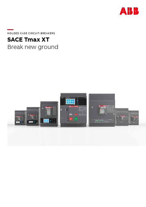
—MOLDED C A SE CIRCUIT-BRE AKERS SACE Tmax XTBreak new groundS ACE TM A X X T M O L D ED C A SE CI R C U IT-B R E A K ER S (M CCB S)—A molded case circuit-breaker range that ensures extreme performance and protection features up to 1600A. Designed to maximize ease of use, integration and connectivity. Built to deliver safety, reliability and quality.—Table of contents004 – 005SACE Tmax XT006 – 007Added values008 – 009Key features012 – 013Choosing the right product 014 – 015 Accessories018 – 021Products in detail024 – 025E lectronic trip units—SACE Tmax XTThe right choice: a complete circuit-breaker range for any solutionSACE Tmax XT2SACE Tmax XT5SACE Tmax XT7SACE Tmax XT44S ACE TM A X X T M O L D ED C A SE CI R C U IT-B R E A K ER S (M CCB S)5SACE Tmax XT3SACE Tmax XT1 SACE Tmax XT66S ACE TM A X X T M O L D ED C A SE CI R C U IT-B R E A K ER S (M CCBS)There is a lot more to the range of SACE Tmax XT than what meets the eye, and the benefits for your business are notice-able. To start with, the whole selection and ordering process has been overhauled to make it far easier to get your hands on the parts you need, speeding things up by about 30%. Installation has been simplified to increase user-friendliness, frames have been streamlined to save space, and improved connectivity - such as Bluetooth and Ekip mobile - will save you considerable time. Another additional benefit is the reliable cloud connectivity and overall increase in information available, meaning diagnostics and maintenance are vastly improved, resulting in less downtime. Finally, thanks to the smart power controller concept, overall energy consumption can be reduced by up to 20%.—Added value each step of the way There is more than just a circuit-breaker in the SACE Tmax XT rangeA new generation of molded case circuit-breakers delivering great added value.7Continuous operationOptimuminterfaceSafety and protectionSpeed up your projects OptimizedlogisticsSpace savingSpeed up your projects Easy toinstallContinuous operation EnergyefficiencyCommissioningThe SACE Tmax XT range offers the potential to save serious time. Thanks to simplified installation of frames, integrating the circuit-breakers into a communication network, trip unit settings per-formed via LCD and Bluetooth and Ekip Mobile con-nectivity , you stand to save up to 40% time overall.Diagnostics and maintenanceWith up to 30% more data available on the cloud and ABB unique power controller concept, it is far easier to diagnose problems and carry out necessary maintenance. This helps to prevent faults, restore energy more quickly and avoid any unnecessary charging of utilities.Energy savingThe SACE Tmax XT range comes with the exclu-sive ABB-patented Ekip Power Controller which monitors installation loads and can limit the amount of power consumed at any time. The result is an overall reduction in power consump-tion of up to 20% and lower energy bills. Further-more, you have 1% energy measurement accuracy according to IEC 61557-12.Selection, ordering and handling 30% faster thanks to part numbersreduction (-10%), online configurator (-40% time) and smart packaging (-30% space).A D D ED VA LU ES8S ACE TM A X X T M O L D ED C A SE CI R C U IT-B R E A K ER S (M CCB S)—01 Choose and custom-ize exactly the rightproducts for your needs, based on how you will use them. 10,000 solutions in one click —02 Effective energy management: 20% less power consump-tion with Power Controller enabled —03 Top reliability:Products designed and tested to exceed stan-dard requirements. More than 30 certificationsCloud-connectedTailor-madetechnologyCloud-connectedBeing connected is a key feature of today’s tech-nology and the SACE Tmax XT range of circuit- breakers offers more than just standalone pro-tection. Being considered key elements of an electrical distribution system, Tmax XT circuit- breakers give you the ability to monitor andmanage a wealth of information, easily, wherever you are. So even when on the road, anytime of the day or night, the power of full-access flexi-bility is in your hands.—Being able to monitor everything while being off-site provides a genuine feeling of you being in control at all times.Tailor-made solutionsJust because your project is complex, this does not mean your circuit-breaker setup has to be. All frames from XT1 to XT7 provide a common pro d uct experience that is backed up by a com-prehensive range of accessories with intuitive interfaces and ergonomic design. With maximum Outstanding technologyFlexibility is nothing without performance and the SACE Tmax XT range is able to deal with the most extreme breaking capacities, regardless of operating voltage, application, and environmen-tal conditions. Combined with the most precise electronic trip units in the smallest of frames, this ensures continuity of service and equipment pro-tection at all times.Top-level qualityAlmost a century of research and experience results in highly-reliable, top-level products that are ready to face all future challenges. Products like the SACE Tmax XT range set standards for edge technologies. Safety, product quality and reliability under pressure are fundamental to all ABB prod-ucts and the SACE Tmax XT range is no different.—Break new ground Key features of an outstanding product9—01—03—02—E A S E OF US E A N D I NS TA LL ATI O NMaximum flexibility for every application – SACE Tmax XT sets the new standard for electrical installations.Easy selection, one-size-fits-all accessories and intuitive design pave the way for smart manufacturing of panels and fast upgrades. Even for the most critical projects.12S ACE TM A X X T M O L D ED C A SE CI R C U IT-B R E A K ER S (M CCBS)Heavy duty Basic functionalityThermal-magnetic, Ekip DipEkip Touch/Hi-Touch —• Standard performance• Icu 70kA at 415/480V AC —• Extreme breaking capacity • 200kA at 415V AC• 100kA at 690V AC—Thermal-magnetic• TMF - TMD - TMA - TMG - MF - MAElectronic• Ekip Dip LIG - LS/I - LSI - LSIG -G Dip LS/I - M Dip I - M Dip LIU -M Dip LRIUNo communication/No display —Ekip Touch • LSI - LSIG - G Touch LSIG - M Touch LRIU - + Energy M Ekip Hi-Touch • LSI - LSIG - G Hi-Touch LSIG Full connectivity - Advanced logic - Power managementUniversally compatibleThe world of circuit-breakers is a complex one,yet choosing the right device for your individualneeds has never been simpler thanks to SACETmax XT range. Maybe you are looking for a basicprotection device for a standard distributionplant. Or perhaps you need something morecomplex, such as a device that integrates —Choosing the right circuit-breaker has never been so easyYou consider what you need. We’ll show you what is possible.protection, automation, measuring and commu-nication into a cloud-based supervision system. Whatever you are looking for, with a wealth of customization possibilities and a range of possible solutions depending on the breaking part and trip unit you choose, the power of circuit breakingis firmly in your hands.Possible combinations within the rangeBasic functionalityWhether you are a hotel owner or planning a production line,where you need to consider the overall power voltage over aperiod of time, the whole SACE Tmax XT range offers all thecircuit breaking power you need to keep your business run-ning long into the future.Thermal-magnetic, Ekip Dip – manual operationThis either consists of the standard thermal-magnetic tripunit intended for basic protection or the Ekip Dip trip unit,the first level of electronic trip unit that can provide in-creased accuracy, a wider regulation range, delayedshort-circuit protection and individual trip information.Heavy duty When it comes to heavy duty usage – whether it’s ships, chemical parks, mining, or heavy duty machinery – the SACE Tmax XT2, XT4, XT5 and XT7 frames are designed to work well beyond the normal constraints when you will be pushing the limits of your installation to the maximum.Ekip Touch/Hi-Touch – cloud functionality Once you are working with the XT2, XT4 XT5 or XT7 frames, all activity can be remotely monitored via the cloud thanks to the Ekip Touch/Hi-Touch trip units which send all data to the ABB Ability TM EDCS and can be monitored through smart-phone or tablet whenever and wherever you like.CH O OSI N G TH E R I G HT PR O D U C T13Tmax XT1Tmax XT2Tmax XT3Tmax XT4Tmax XT5Tmax XT6Tmax XT7Basic functionality (Icu@415V<70 kA)Heavy duty (Icu@415V>70 kA)Thermal-magnetic trip units Ekip Dip (standard electronic)Ekip Touch/Hi-Touch (smart electronic)14S ACE TM A X X T M O L D ED C A SE CI R C U IT-B R E A K ER S (M CCB S)—Udipsusam esciis pariamet, que et faci quia conet, sit magnatia dolora esciis pariamet, que et faci solupiste dollorpostem pliqui cum image—AccessoriesExpand the capabilities of the SACE Tmax XT rangeIntegrating circuit-breakers into any installation requires different levels of optimization. Whether physical, electrical, operational or safety-focused, accessories take SACE Tmax XT to the next level.AccessoriesA large range of connections has been conceived to match the most common distribution systems. Auxiliary contacts can provide precise information regarding breaker status and plant conditions, maximizing operator awareness and the overall accuracy of a supervision system. In addition, dif-ferent types of coils and motor operator versions, designed to operate with the most common voltage sources and reduced power consumption, enable the possibility to control all installations remotely. Residual current devices up to 630A, sig-naling modules, installation components (e.g. phase barriers, terminal covers), key-locks and padlocks are just a few examples of the care taken to safeguard appliances and operators alike. Metering15Various accessories are also available:1. Breaking unit2. Trip units3. Front4. Polish plate5. Terminal covers6. Auxiliary contacts7. Key lock8. Service releases9. Communication module10. C onversion kit for plug-in/withdrawable versions11. G uide of fixed part in thewithdrawable version 12. Fixed part - FP 13. Front for lever operating mechanism - FLD 14. Stored energy motor operator - MOE 15. Direct rotary handle - RHD 16. Transmitted rotary handle - RHE 17. Conversion kit RHE > RHS 18. Cable rack 19. Phase separators 20. R ear orientated terminals - R 21. F ront extended spread terminals - ES 22. Front terminals for copper-aluminium - FC CuAl 23. Front extended terminals - EF 24. Residual current release2419162122231761012911723138520151418415ACCE SSO R IE SS ACE TM A X X T M O L D ED C A SE CI R C U IT-B R E A K ER S (M CCB S)—PER FO R M A NCE A N D PROTEC TI O NContinuity of service and equipmentprotection – SACE Tmax XT sets the new standard when extreme breaking capacity is needed. Sharing the same logic, interfaces andfeatures regardless of operating voltageand environmental conditions. Embeddingthe most advanced protection into thesmallest of frames.S ACE TM A X X T M O L D ED C A SE CI R C U IT-B R E A K ER S (M CCB S)SACE Tmax XT1The founderSmall, reliable, versatile. Your reliable partner for all standard applications.At a glance:• Up to 160A• For basic functionalities• Dimensions 76.2x70x130 (WxDxH mm)• Thermal-magnetic trip unit SACE Tmax XT2The aspirerCompact yet powerful. It fits everywhere and is able to deal with all complex tasks. At a glance:• Up to 160A• For heavy duty• Dimensions 90x82.5x130 (WxDxH mm)• Thermal-magnetic, Ekip Dip,Ekip Touch/Hi-Touch18—The SACE Tmax XT range at a glance The world of circuit breaking and circuit protection in your handsThe SACE Tmax XT range takes circuit protection to the nextlevel. Designed to perform at extremely high levels, simpleto install and able to provide increasingly better safety,there is a frame to meet each and every one of your require-ments. From a basic solution for standard applications -such as hotels - through to advanced, heavy-duty applica-tions with cloud connectivity for ships, chemical parks orairports, the new range has got it covered: securely, profes-sionally, reliably.19PR O D U C TS I N D E TA I LSACE Tmax XT4The entrepreneur A forward-thinking, multitasker. It finds solutions for all levels of complexity.At a glance:• Up to 250A • For heavy duty • Dimensions 105x82.5x160 (WxDxH mm)• Thermal-magnetic, Ekip Dip,Ekip Touch/Hi-TouchSACE Tmax XT3The workhorseSmall and experienced. For standardapplications that need few efforts.At a glance:• Up to 250 A• For basic functionalities• Dimensions 105x70x150 (WxDxH mm)•Thermal-magnetic trip unitS ACE TM A X X T M O L D ED C A SE CI R C U IT-B R E A K ER S (M CCBS)SACE Tmax XT5The gamechanger.Compact, extremely powerful and flexible. It shows the world what a circuit-breaker of the future can do, today. At a glance:• Up to 630A• For heavy duty• Dimensions 140x103x205 (WxDxH mm)• Thermal-magnetic, Ekip Dip, Ekip Touch/Hi-Touch SACE Tmax XT6The carpenterBuilt to last. It completes all assignments it has been entrusted with.At a glance:• Up to 1000A• For basic functionalities• Dimensions 210x103.5x268 (WxDxH mm)• Thermal-magnetic, Ekip Dip2021PR O D U C TS I N D E TA I LSACE Tmax XT7 M The motorized superhero The ultimate choice, with motor. It deals with the most heavy-duty demands smoothly.At a glance:• Up to 1600A • For heavy duty • Dimensions 210x178x268 (WxDxH mm)• Ekip Dip, Ekip Touch/Hi-TouchSACE Tmax XT7The superheroThe ultimate choice. It deals with the mostheavy-duty demands effortlessly.At a glance:• Up to 1600A• For heavy duty• Dimensions 210x166x268 (WxDxH mm)•Ekip Dip, Ekip Touch/Hi-TouchS ACE TM A X X T M O L D ED C A SE CI R C U IT-B R E A K ER S (M CCB S)—DATA A N D CO N N EC TI V IT YPlant management of the future – SACE Tmax XT sets the new standard in modern plant and energy management. Access, monitor and control information remotely, anywhere, at any time. Improving efficiency and saving energy.24S ACE TM A X X T M O L D ED C A SE CI R C U IT-B R E A K ER S (M CCB S)—01 All the tools neededto set up a compe-tent and effectiveenergy managementstrategy. 30% moreinformation abouta running system toempower ABB Ability TM P r o t e c t i o n a n di n f o r m a t i o n AccuracyThermal-magnetic trip units Thermal-magnetic trip units are intended for the protection of AC and DC networks. They are a solution for basic protection such as overloads and short-circuits.Ekip Dip trip unitsEkip Dip trip units represent the first level ofelectronic trip unit and are used to protect ACnetworks. Compared to thermal-magnetic tripunits, they can provide increased accuracy, a widerreg ulation range, delayed short-circuit protection,in di v idual trip information and test capa bility.Ekip Touch/Hi-Touch trip units Ekip Touch/Hi-Touch trip units offer state-of-the-art technology for AC-network protection. These trip units integrate a great number of protection and automation functionalities, performed with best-in-class accuracy. Measurement and supervi-sion data can be transmitted both on the local communication network (the most popular com-munication protocols are available) or directly over the Internet. Configuration of the trip unit is extremely user-friendly, mainly on the sizes where a color touchscreen display is available. Furthermore, as operational requirements evolve,for the first time ever customers can downloadnew functions from the ABB Ability Marketplace TM ,choosing among more than fifty different protec-tion, metering and automation functionalities.—Electronic trip units Ekip Dip and Ekip Touch/Hi-Touch The network under controlWhen it comes to accurate protection of the network, you cannot go wrong with Ekip Dip and Touch technology.Trip unit rangeThe protection units available for the SACE Tmax XTrange is organized in three layers, characterizedby increasing performance, interfaces, informa-tion sets and integration functions. Each layerincludes several trip unit versions, designed to match specific application needs such as distribu-tion, generator protection and motor protection.25CampaignS ACE TM A X X T M O L D ED C A SE CI R C U IT-B R E A K ER S (M CCB S)—QUA LIT Y A N D R ELI A B I LIT YAbsolute attention to detail, withstyle – from design to manufacturing, SACETmax XT sets the new standard for edgetechnologies. Almost a century of research and experience means top-level products that areready to face future challenges.© Copyright 2019 ABB. All rights reserved.Specifications subject to change without notice.9A K K 107046A 3308 - 05/2019—ABB SACEElectrification business Smart Power business line 5, Via PescariaI-24123 Bergamo - ItalyPhone: +39 035 395-111go.abb/xt。
模具保护器操作手册(新版)

模具保护器操作说明书
安全须知
1.关于使用环境,使用条件 本器具是屋内使用的,不可在屋外使用,如果在屋外使用,会引起触电,火 灾。 本器具请在容许温度范围内使用,否则会引起破损,变形,火灾和灯管的破 类 请不要在潮湿和有水的地方使用,否则会引起触电,火灾。 请不要在不安定的场所或易燃物的附近使用,否则会引起掉落,造成火灾, 受伤。 请使用指定的灯管,如果使用指定以外(不合适)的灯管,会造成器具的破 损,灯管的破裂。 请不要在带有强磁界, 强磁场装置的附近使用, 由于电磁波会造成器具工作 错误及动作画像混杂。 本器具内部以电子原件构成, 请在指定条件下使用。 没有严格遵守使用条件, 会造成器具破损,触电,火灾。 请使用指定的照相机座,照明磁力坐。如果选择错误,会造成颠倒,器具的 破损,受伤事故。
6.关于保管 请不要在多灰尘的温度高, 易结水珠的环境下保管, 否则会造成器具的故障, 绝缘不良。 再使用时请务必点检后在使用,否则可能会引起触电。火灾。
第6页 共 29 页 中国厦门伟迪康科技有限公司 TEL:0592-2102891
模具保护器操作说明书
硬件构成
主机-------------------------------------------------------------------------1 台 触摸屏-----------------------------------------------------------------------1 台 CCD 相机-------------------------------------------------------------------1 台 标准镜头--------------------------------------------------------------------1 台 相机用线缆-----------------------------------------------------------------1 条 相机用机架-----------------------------------------------------------------1 套 电源--------------------------------------------------------------------------1 套 红外照明光源--------------------------------------------------------------1 套 触摸屏线缆------------------------------------------------------------------1 条 1/0 线盒-----------------------------------------------------------------------1 套
模理特模具保护器word版

模理特模具保护器目录第1章模理特模具监控保护装置介绍1.1、概述1.2、功能简介1.3、产品特征第2章安全上的注意点2.1、安全注意事项2.2、关于安装使用第3章使用前的准备3.1、线缆类的链接3.2、其它使用前的准备第4章操作方法4.1、插入电源4.2、主要项目4.3、条件设定4.4、登录基准影像4.5、区域设定4.6、确认4.7、测试4.8、系统4.9、时间、感度的调整4.10、2台照相机确认功能4.11、扩大表示功能第5章选配功能第6章故障诊断第7章 FK-601规格第8章信号链接图第9章注意事项第1章模理特模具监控保护装置介绍1.1概述国内领先技术、国际先进技术的注塑机模具保护系统。
模具保护器(又称模具监视器或电子眼),模理特模具监视能在一个完整的成型周期内对所关心的模具型腔面进行两次拍照,即一检和二检,通常一检所选择的时机为型开刚刚完成,顶出动作还没有进行的时刻,这时的型腔多附有刚成型出的产品,即有品腔,这时间拍照通常会检出所成型的产品是否不良,是否有留定模的产品;通常二检所选择的时机为顶出回退到位(不使用机械手时)或机械手已到安全区域且顶出回退到位,在合模动作还没有动作之前。
这时的模具型腔不含有成型品,即无品腔,这时拍照会检出是否有未脱落的制品,还能帮助判断镶件、顶杆和滑块的位置或状态是否正常。
当一检失败时,会有报警灯提示,又可以加入不顶出的连锁保护,当二检失败时,也有报警灯提示,并指示注塑机不准合模,这样就有效地保护了模具,避免不必要的损失。
1.2功能简介注塑机运行时,每个周期内昂贵的模具都可能因为残留或滑块错位而有损坏的危险,模具保护器可以防止这些情况发生!最先进的机器视觉技术用来进行检查,自动防止闭模并报警,保护昂贵的模具,避免停机修模,保障交货工期。
主要用途 1. 闭模前进行模穴、模芯、产品残留的确认 2. 滑块位置、顶出返回位置等位置确认 3. 插件插入错误确认 4. 顶出少折断确认 5. 检测产品是否有缺料或毛边产生 6. 检查多穴产品是否缺失 7. 检查多色产品混色是否正确 8. 防止残次品连续出现 9. 减少多余的顶针动作功能特点 1. 多种相机可供选择,分辨率1280X1024,1024X768,752X480,640X512,640X480 2. 任意形状ROI,可适应各种复杂模具和产品 3. 支持任意多个ROI 4. 每个ROI可单独设置灵敏度和传感单元密度 5. 自动ROI生成功能,极大简化检测设置过程 6. 触摸显示屏控制,操作方便 7. 分级密码控制,防止一般操作人员误操作。
易安电源防御模具电路保护器PDG23N0150E3RN说明说明书
Eaton PDG23N0150E3RNEaton Power Defense molded case circuit breaker, Globally Rated, Frame 2, Three Pole, 150A, 85kA/480V, PXR20 LSIG w/ Relays, No TerminalsEaton Power Defense molded case circuit breakerPDG23N0150E3RN 78667922392588.9 mm 152.4 mm 104.6 mm 1.82 kg Eaton Selling Policy 25-000, one (1) year from the date of installation of theProduct or eighteen (18) months from thedate of shipment of the Product,whichever occurs first.RoHS Compliant UL 489IEC 60947-2CSACCC MarkedProduct NameCatalog Number UPCProduct Length/Depth Product Height Product Width Product Weight WarrantyCompliancesCertifications150 AComplete breaker 2Three-polePD2 Global Class A PXR 20 LSIG600 Vac600 VNo Terminals85 kAIC at 480 Vac 10 kAIC Icu/ 5 kAIC Ics/ 21 kAIC Icm @690V (IEC) 30/25 kAIC @600V (UL/CSA) 150 kAIC @240V (UL) 22 kAIC Icu @250 Vdc30/25 kAIC Icu/ 15/13 kAIC Ics @525V South Africa (IEC) 70 kAIC Icu/ 50 kAIC Ics/ 154 kAIC Icm @440V (IEC) 70 kAIC Icu/ 70 kAIC Ics/ 154 kAIC Icm @380-415V (IEC) 85 kAIC @480V (UL)65 kAIC Icu/ 40 kAIC Ics/ 143 kAIC Icm @480V Brazil (IEC) 150 kAIC Icu/ 100 kAIC Ics/ 330 kAIC Icm @240V (IEC) 22 kAIC Icu @125 Vdc 25 kAIC @600V (UL/CSA)150 AEaton Power Defense MCCB PDG23N0150E3RN 3D drawing Amperage Rating Circuit breaker frame type Frame Number of poles Circuit breaker type Class Trip Type Voltage rating Voltage rating - max Terminals Interrupt rating Interrupt rating rangeTrip rating 3D CAD drawing packageApplication notesPower Xpert Protection Manager x64Consulting application guide - molded case circuit breakersBrochuresPower Defense brochurePower Defense molded case circuit breaker selection posterPower Defense technical selling bookletPower Defense molded case circuit breakers - Frame 2 product aidCatalogsMolded case circuit breakers catalogPower Xpert Release trip units for Power Defense molded case circuit breakersCertification reportsEU Declaration of Conformity - Power Defense molded case circuit breakersPDG4 CB reportPDG4 CCC certificationPDG2 CB reportPower Defense Declaration concerning California’s Proposition 65Installation instructionsPower Defense Frame 2 global terminal shield, 3 pole - IL012330EN Power Defense Frame 2 terminal kit - PDG2X3(2)(4)TA225RF instructions - IL012245EN H01Power Defense Frame 2/3/4/5/6 voltage neutral sensor module wiring instructions – IL012316ENPower Defense Frame 2 locking devices and handle block instructions - IL012149ENPower Defense Frame 2 handle mech direct rotary handle instructions - IL012134ENPower Defense Frame 2 handle mech variable depth rotary handle instructions - IL012136ENPower Defense Frame 1-2-3-4 IP door barrier assembly instructions - IL012278ENPower Defense Frame 2 tunnel terminal kits - PDG2X1TA225K instructions- IL012239EN H01Power Defense Frame 2 multi wire connector kit -PDG2X3(2)(4)TA2253W instructions - IL012243EN H01Power Defense Frame 1 IEC and Frame 2 Rotary Mechanism with NFPA Handle Attachment Instructions (IL012260EN).pdfPower Defense Frame 2 tunnel terminal (aluminum), 50A, 3 pole instructions - IL012236EN H03Power Defense Frame 2 tunnel terminal (aluminum), 150A, 3 poleinstructions - IL012238EN H03Power Defense Frame 2 multi wire connector kit -PDG2X3(2)(4)TA2256W instructions - IL012242EN H01Power Defense Frame 2 PDG2 and PDC(E)9 breaker instructions -IL012106ENPower Defense Frame 2 Bell Alarm Switch Instructions (IL012154EN).pdf Power Defense Frame 2 Direct Rotary Handle Assy With Interlock Version Instructions (IL012138EN).pdfPower Defense Frame 2 screw terminal_end cap kit, 225A, 3 pole instructions - IL012258EN H01Power Defense Frame 2 shunt trip UVR instructions - IL012130EN Power Defense Frame 2 clamp terminal (steel), 20A, 3 pole instructions - IL012246EN H03Power Defense Frame 2 terminal kit - PDG2X3(2)(4)TA150RF instructions - IL012244EN H01Power Defense Frame 2 box terminal (aluminum), 225A, 3 pole instructions - IL012235EN H03Power Defense Frame 2 tunnel terminal (aluminum), 100A, 3 pole instructions - IL012237EN H03Power Defense Frame 2 box terminal (steel), 100A, 3 pole instructions - IL012234EN H03Installation videosPower Defense Frame 2 withTMTU, Shunt Trip_UVR Animated Instructions.rhPower Defense Frame 2 Bell Alarm with PXR Animated Instructions.pdf.rh Power Defense Frame 2 Handle Mech Variable Depth Rotary Handle Animated Instructions.rhPower Defense Frame 2 TMTU Aux, Alarm, ST and UVR Animated Instructions.rhPower Defense Frame 2 Locking Devices and Handle Block Animated Instructions.pdf.rhMultimediaPower Defense Frame 3 Variable Depth Rotary Handle Mechanism Installation How-To VideoPower Defense Frame 2 Aux, Alarm, Shunt Trip, and UVR How-To Video Power Defense Frame 2 Variable Depth Rotary Handle Mechanism Installation How-To VideoPower Defense Frame 2 Direct Rotary Handle Mechanism Installation How-To VideoEaton Power Defense for superior arc flash safetyPower Defense Frame 6 Trip Unit How-To VideoPower Defense BreakersEaton Corporation plc Eaton House30 Pembroke Road Dublin 4, Ireland © 2023 Eaton. All Rights Reserved. Eaton is a registered trademark.All other trademarks areproperty of their respectiveowners./socialmediaPower Defense Frame 5 Trip Unit How-To Video Power Defense molded case circuit breakers Eaton Specification Sheet - PDG23N0150E3RN Power Defense time current curve Frame 2 - PD2Intelligent power starts with accurate, actionable data Making a better machineMolded case and low-voltage power circuit breaker health Single and double break MCCB performance revisited Intelligent circuit protection yields space savings Molded case and low-voltage breaker health Safer by design: arc energy reduction techniquesSpecifications and datasheetsTime/current curvesWhite papers。
Eaton PDG24F0100B2NN 电子保护模具电路保护器说明书
Eaton PDG24F0100B2NNEaton Power Defense molded case circuit breaker, Globally Rated, Frame 2, Four Pole (100% N), 100A, 25kA/480V, PXR10 LSI TU, No TerminalsGeneral specificationsEaton Power Defense molded case circuit breakerPDG24F0100B2NN 78667921463388.9 mm 152.4 mm 139.5 mm 2.46 kg Eaton Selling Policy 25-000, one (1) year from the date of installation of theProduct or eighteen (18) months from thedate of shipment of the Product,whichever occurs first.RoHS Compliant IEC 60947-2UL 489CCC MarkedCSAProduct NameCatalog Number UPCProduct Length/Depth Product Height Product Width Product Weight WarrantyCompliancesCertifications100 AComplete breaker 2Four-pole (100% N)PD2 Global Class A PXR 10 LSI600 Vac 600 V100% neutral protection No Terminals25 kAIC at 480 Vac18 kAIC Icu/ 15/13 kAIC Ics/ 37.8 kAIC Icm @525V South Africa (IEC)14 kAIC @600V (UL/CSA)25 kAIC @480V (UL)25 kAIC Icu/ 25 kAIC Ics/ 52.5 kAIC Icm @380-415V (IEC)25 kAIC Icu/ 20 kAIC Ics/ 52.5 kAIC Icm @440V (IEC)35 kAIC @240V (UL)35 kAIC Icu/ 35 kAIC Ics/ 73.5 kAIC Icm @240V (IEC)20 kAIC Icu/ 20 kAIC Ics/ 42 kAIC Icm @480V Brazil (IEC)10 kAIC Icu @125 Vdc10 kAIC Icu @250 Vdc Eaton Power Defense MCCB PDG24F0100B2NN 3D drawingConsulting application guide - molded case circuit breakersPower Xpert Protection Manager x64Power Defense molded case circuit breaker selection posterPower Defense brochurePower Defense technical selling bookletPower Defense molded case circuit breakers - Frame 2 product aidPower Xpert Release trip units for Power Defense molded case circuit breakersMolded case circuit breakers catalogAmperage RatingCircuit breaker frame type FrameNumber of poles Circuit breaker type ClassTrip TypeVoltage rating Voltage rating - maxProtection TerminalsInterrupt rating Interrupt rating range 3D CAD drawing package Application notes BrochuresCatalogsCertification reportsPDG2 CB reportPDG4 CCC certificationPDG4 CB reportEU Declaration of Conformity - Power Defense molded case circuit breakersInstallation instructionsPower Defense Frame 2 tunnel terminal (aluminum), 50A, 4 pole instructions - IL012236EN H04Power Defense Frame 2 locking devices and handle block instructions - IL012149ENPower Defense Frame 2 bell alarm switch instructions - IL012154EN Power Defense Frame 2 Bell Alarm Switch Instructions (IL012154EN).pdf Power Defense Frame 2 PDG2 and PDC(E)9 breaker instructions -IL012106ENPower Defense Frame 2 multi wire connector kit -PDG2X3(2)(4)TA2256W instructions - IL012242EN H01Power Defense Frame 2 tunnel terminal (aluminum), 150A, 4 pole instructions - IL012238EN H04Power Defense Frame 2/3/4/5/6 voltage neutral sensor module wiring instructions – IL012316ENPower Defense Frame 2 multi wire connector kit -PDG2X3(2)(4)TA2253W instructions - IL012243EN H01Power Defense Frame 2 screw terminal_end cap kit, 225A, 3 pole instructions - IL012258EN H01Power Defense Frame 2 tunnel terminal (aluminum), 100A, 4 pole instructions - IL012237EN H04Power Defense Frame 1-2-3-4 IP door barrier assembly instructions -IL012278ENPower Defense Frame 2 tunnel terminal kits - PDG2X1TA225K instructions- IL012239EN H01Power Defense Frame 2 terminal kit - PDG2X3(2)(4)TA225RF instructions - IL012245EN H01Power Defense Frame 2 box terminal (aluminum), 225A, 4 pole instructions - IL012235EN H04Power Defense Frame 2 clamp terminal (steel), 20A, 4 pole instructions - IL012246EN H04Power Defense Frame 2 shunt trip UVR instructions - IL012130EN Power Defense Frame 2 box terminal (steel), 100A, 4 pole instructions - IL012234EN H04Power Defense Frame 1 IEC and Frame 2 Rotary Mechanism with NFPA Handle Attachment Instructions (IL012260EN).pdfPower Defense Frame 2 global terminal shield, 4 pole - IL012330ENPower Defense Frame 2 terminal kit - PDG2X3(2)(4)TA150RF instructions - IL012244EN H01Installation videosPower Defense Frame 2 TMTU Aux, Alarm, ST and UVR Animated Instructions.rhPower Defense Frame 2 withTMTU, Shunt Trip_UVR Animated Instructions.rhPower Defense Frame 2 Bell Alarm with PXR Animated Instructions.pdf.rhMultimediaPower Defense Frame 3 Variable Depth Rotary Handle Mechanism Installation How-To VideoPower Defense Frame 2 Direct Rotary Handle Mechanism Installation How-To VideoPower Defense Frame 2 Variable Depth Rotary Handle Mechanism Installation How-To VideoPower Defense Frame 2 Aux, Alarm, Shunt Trip, and UVR How-To Video Power Defense molded case circuit breakersPower Defense BreakersPower Defense Frame 6 Trip Unit How-To VideoEaton Power Defense for superior arc flash safetyPower Defense Frame 5 Trip Unit How-To VideoSpecifications and datasheetsEaton Specification Sheet - PDG24F0100B2NNTime/current curvesPower Defense time current curve Frame 2 - PD2White papersMolded case and low-voltage power circuit breaker healthIntelligent circuit protection yields space savingsMaking a better machineIntelligent power starts with accurate, actionable dataSingle and double break MCCB performance revisitedSafer by design: arc energy reduction techniquesMolded case and low-voltage breaker healthEaton Corporation plc Eaton House30 Pembroke Road Dublin 4, Ireland © 2023 Eaton. All Rights Reserved. Eaton is a registered trademark.All other trademarks areproperty of their respectiveowners./socialmedia。
Eaton LGE340035B20G电子模具保护器技术参数手册说明书
Eaton LGE340035B20GEaton Series G molded case circuit breaker, LG-frame, LG, Digitrip 310 RMS, Electronic LSG trip, Three-pole, 400A, 65 kAIC at 240 Vac, 35 kAIC at 480 Vac, 18 kAIC at 600 Vac, Line and load, Metric, High load alarm, 50/60 Hz, 80% ratedGeneral specificationsEaton Series G complete molded case circuit breakerLGE340035B20G 7866855820474.09 in5.48 in 5.48 in 15.3 lb Eaton Selling Policy 25-000, one (1) year from the date of installation of theProduct or eighteen (18) months from thedate of shipment of the Product,whichever occurs first.CE Marked CSA CertifiedIEC RatedUL Listed LG breaker is HACR ratedProduct NameCatalog Number UPCProduct Length/Depth Product Height Product Width Product Weight WarrantyCompliancesCertificationsCatalog Notes65 kAIC at 240 Vac 35 kAIC at 480 Vac 18 kAIC at 600 VacLG80% rated400 AThree-poleSeries GMetricComplete breakerLG50 to 60 HzComplete breakerHigh load alarmLine and loadElectronic LSG Application of Tap Rules to Molded Case Breaker Terminals Application of Multi-Wire Terminals for Molded Case Circuit BreakersMulti-wire lugs product aidComprehensive circuit protection for control panel applicationsCircuit breaker motor operators product aidPower metering and monitoring with Modbus RTU product aid310+ MCCB product family pocket folderCurrent limiting molded case circuit breaker module for series G, JG and CLCurrent limiting molded case circuit breaker module product aid Molded case circuit breakers providing higher levels of selective coordination product aidSeries G MCCB quick selectorHigh performance operating handles for Series G circuit breakers product aidMotor protection circuit breakers product aidPlug-in adapters for molded case circuit breakers product aid StrandAble terminals product aidBreaker service centersJ-Frame 310+ and L-Frame 310+ Molded-case circuit breakersEaton's Volume 4—Circuit ProtectionMolded case circuit breakers catalogInstallation Instructions for Series G L-Frame Circuit BreakersNG and ND-Frame molded case circuit breakersMOEM MCCB product selection guideL-Frame 310+ Molded-case circuit breakers 100A-600AEaton Specification Sheet - LGE340035B20GInterrupt ratingFrameRatingAmperage Rating Number of polesSeriesMounting hardwareTypeCircuit breaker type Frequency ratingCircuit breaker frame type Alarm lockoutTerminalsTrip Type Application notesBrochuresCatalogsInstallation instructions Specifications and datasheetsEaton Corporation plc Eaton House30 Pembroke Road Dublin 4, Ireland © 2023 Eaton. All Rights Reserved. Eaton is a registered trademark.All other trademarks areproperty of their respectiveowners./socialmedia。
爱本FD2040系列完整型模具封闭电路保护器说明说明书
Eaton FD2040Eaton Series C complete molded case circuit breaker, F-frame, FD, Complete breaker, Fixed thermal, Fixed magnetic trip type, Two-pole, 40 A, 600 Vac, 250 Vdc, Load side, 50/60 HzGeneral specificationsEaton Series C complete molded case circuit breakerFD20407866793122543.38 in 6 in2.75 in3.05 lb Eaton Selling Policy 25-000, one (1) year from the date of installation of the Product or eighteen (18) months from the date of shipment of the Product, whichever occurs first.UL Listed Product NameCatalog Number UPCProduct Length/Depth Product Height Product Width Product Weight WarrantyCertificationsSeries C65 kAIC at 240 Vac35 kAIC at 480 VacFFD50/60 HzComplete breakerLoad side600 Vac, 250 Vdc40 AFixed thermal, fixed magnetic Two-pole UL listed 100%-rated molded case circuit breakersApplication of Tap Rules to Molded Case Breaker Terminals Application of Multi-Wire Terminals for Molded Case Circuit BreakersCircuit breaker motor operators product aidPlug-in adapters for molded case circuit breakers product aid StrandAble terminals product aidMotor protection circuit breakers product aidPower metering and monitoring with Modbus RTU product aidMulti-wire lugs product aidCurrent limiting Series C molded case circuit breakers product aid MOEM MCCB Product Selection GuideBreaker service centersCounterfeit and Gray Market Awareness GuideEaton's Volume 4—Circuit ProtectionMolded case circuit breakers catalogTime Current Curves for Series C® F-Frame Circuit BreakersF-frame Molded Case Circuit Breaker DrawingFD2 2D Drawing XchangeFD2 3D InventorFD2 3D Model XchangeFD2 2D PDFInstallation Instructions for EHD, EDB, EDS, ED, EDH, EDC, FDB, FD, HFD, FDC, HFDDC Circuit Breakers and Molded Case SwitchesCircuit Breakers ExplainedCircuit breakers explainedEaton Specification Sheet - FD2040F-Frame 310+ Molded-case circuit breakers 15-225ASeries C G-Frame molded case circuit breakers time current curves MOEM MCCB product selection guideSeriesInterrupt ratingFrameCircuit breaker type Frequency ratingCircuit breaker frame type TerminalsVoltage rating Amperage RatingTrip TypeNumber of poles Application notesBrochuresCatalogsDrawingsInstallation instructions MultimediaSpecifications and datasheetsEaton Corporation plc Eaton House30 Pembroke Road Dublin 4, Ireland © 2023 Eaton. All Rights Reserved. Eaton is a registered trademark.All other trademarks areproperty of their respectiveowners./socialmediaSeries C F-Frame molded case circuit breakersSeries C J-Frame molded case circuit breakers time current curves。
- 1、下载文档前请自行甄别文档内容的完整性,平台不提供额外的编辑、内容补充、找答案等附加服务。
- 2、"仅部分预览"的文档,不可在线预览部分如存在完整性等问题,可反馈申请退款(可完整预览的文档不适用该条件!)。
- 3、如文档侵犯您的权益,请联系客服反馈,我们会尽快为您处理(人工客服工作时间:9:00-18:30)。
模具保护器操作说明书
ROI
(P.14)
区域设定,设置检测区域; 登陆基准画面 (P.15) 使其成为确认基准的画像; 设置(P.15) 设定相机拍照延时时间、次数、检测灵敏度; 相机参数 (P.16) 设定相机曝光、增益 基准画面设定(P.17) 设定基准画面灵敏度、忽略、报警点忽略、边缘过滤参数 I/O 设定特殊功能。一般不建议进行设定! 关机 关闭监视主机,关闭后系统不影响成型机正常使用 重启 重新启动监视器 清空 归零统计的模数和通过数 报告 查看历史 50 张的 NG 或 OK 图片 升级 进行对软体升级操作,在厂方提供升级软体后并按厂方电话支持下操
6.关于保管 请不要在多灰尘的温度高, 易结水珠的环境下保管, 否则会造成器具的故障, 绝缘不良。 再使用时请务必点检后在使用,否则可能会引起触电。火灾。
第6页 共 29 页 中国厦门伟迪康科技有限公司 TEL:0592-2102891
模具保护器操作说明书
硬件构成
主机-------------------------------------------------------------------------1 台 触摸屏-----------------------------------------------------------------------1 台 CCD 相机-------------------------------------------------------------------1 台 标准镜头--------------------------------------------------------------------1 台 相机用线缆-----------------------------------------------------------------1 条 相机用机架-----------------------------------------------------------------1 套 电源--------------------------------------------------------------------------1 套 红外照明光源--------------------------------------------------------------1 套 触摸屏线缆------------------------------------------------------------------1 条 1/0 线盒-----------------------------------------------------------------------1 套
第5页 共 29 页 中国厦门伟迪康科技有限公司 TEL:0592-2102891
模具保护器操作说明书
请切断电源后进行灯管的交换,部品的更换,清扫,如果不切断电源会引起触 电。的交换,请切断电源后进行灯管的交换,部品的更换,清扫,如果不切断 电源会引起触电。 电线类要进行日常点检。点检的结果如发现异常,请按照说明说进行处理。 否则会造成触电,火灾。 冷缺口是否被灰尘堵塞, 请日常点检并清扫, 否则会造成器具的故障, 火灾。 清洁镜片时不可刮伤镜片,否则会造成镜片的破损,划伤。 螺丝类因震动而松掉时,请按照使用说明说进行处理。否则会由于掉落而造成 物品的损坏的人员的受伤。 请不要在被灰尘,油污堵塞的状态下使用,否则会引起火灾。 请使用制定的灯管,如果使用指定以外(不合适)的灯管会造成器具的破损, 灯管的破裂。 安装灯管时,请正确地插入至插座内,否则会造成灯管,插座的破损。 更换部品时。请使用厂商指定的部品并依据使用说明书正确地处理,否则会造 成器具的机能劣化,故障,触电,火灾。 除了日常点检之外, 请依据厂商和专家的指示再做定期点检, 否则会造成器 具的劣化,故障,触电,火灾。
© 2009 中国厦门伟迪康科技有限公司 版权所有 网站: 支持热线: 0592-2102893
第2页 共 29 页 中国厦门伟迪康科技有限公司 TEL:0592-2102891
模具保护器操作说明书
目
录
安全须知------------------------------------------------------------------------3 硬件构成------------------------------------------------------------------------8 接口接线-----------------------------------------------------------------------10 软体界面纵缆-----------------------------------------------------------------12 操作方法-----------------------------------------------------------------------14 1、ROI 设定----------------------------------------------------------------------14 2、登陆基准画面----------------------------------------------------------------15 3、设定拍照次数-----------------------------------------------------------------15 4、拍照延时设定----------------------------------------------------------------16 5、相机参数设定----------------------------------------------------------------16 6、基准画面设定----------------------------------------------------------------17 灵敏度、面积设定----------------------------------- -------------------17 忽略不检测区域----------------------------------------------------------18 报警点自动忽略----------------------------------------------------------18 边缘过滤参数设定-------------------------------------------------------18 报警历史查看-----------------------------------------------------------------21 1 次报警 NG 处理操作------------------------------------------------------22 2 次报警 NG 处理操作------------------------------------------------------23 I/O 信号接线------------------------------------------------------------------24 操作问题故障处理-----------------------------------------------------------27 注意事项-----------------------------------------------------------------------28
2.关于安装,设置 请在安装, 设置本器具前务必认真阅读安装说明书及注意书, 并且请在阅读 后认真保管,必要时请活用。 本器具的安装,设置请让让专业人士进行。如果安装人员不熟悉,会造成错
第4页 共 29 页 中国厦门伟迪康科技有限公司 护器操作说明书
误。施工时请电气专业人员施工,如果不熟悉会造成施工错误。请务必安装地 线,如果不安装地线会引起触电,机器故障。照明台,照明坐的安装,设置必 须与周围的物品保持充分的距离后安装。如果过近,会造成火灾。 本器具的安装, 设置要在不接触万能插座及散热器的条件下进行。 如果过近, 会造成火灾。 3.关于使用前的准备 请使用本器具前务必认真阅读使用说明说, 并且请在阅读后认真保管, 必要 时请活用。 本器具使用前的准备请让熟练者进行,否则会在成错误。 接续电源时请依照使用说明书正确地进行, 如果接续不全, 会由于接触不良 而造成火灾。 、 请取出器具内部运输用的缓冲材后在使用。 如果有残留物体时, 可能会引起 器具的破损,火灾。 4.关于使用方法 安装本器具时,请让专业者进行,否则会造成错误。 打开照明灯或关闭后,请不要马上触摸照明台周围。因为高温,会造成烫伤。 请务必连接地线,如果不连接地线,会引起触电,机器故障。 地震等天灾后,请在专家点检后使用。未熟练者的对应会造成错误。 不要分解,改造本器具。会造成破损,触电,火灾。 5.关于保养点检 请进行器具的日常点检,如果点检后发现异常请依照使用说明书进行处理。 器具的点检请让熟悉者进行,否则会造成错误。
模具保护器操作说明书
模具保护装置
使用说明书
版
本:V2.1.7
发布日期:2010-07-1 厦门伟迪康科技有限公司
第1页
共 29 页
中国厦门伟迪康科技有限公司
TEL:0592-2102891
模具保护器操作说明书
本手册中所提及的其它软硬件软件产品的商标与名称,都属于相应公司所 有。 本手册的版权属于中国厦门伟迪康科技有限公司所有。未得到本公司的正 式许可,任何组织或个人均不得以任何手段和形式对本手册内容进行复制或传 播。 本手册的内容若有任何修改, 恕不另行通知. 有关更新请查阅本公司网站。 谢谢您的使用!