Chroma 6310系列电子负载操作指导书
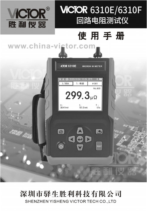
胜利仪器 VICTOR 6310E 6310F回路电阻测试仪 说明书
目录安全须知 (1)一.简介 (2)二.型号区别 (3)三.技术规格 (3)四.结构 (5)五.操作 (6)1.操作 (6)2.测试 (9)六.电池管理 (13)七.装箱单 (14)安全须知感谢您购买了本公司的回路电阻测试仪,为了更好地使用本产品,请一定:——详细阅读本用户手册,操作者必须完全理解手册说明并能熟练操作本仪表后才能进行实际测试。
——严格遵守本手册所列出的安全规则及注意事项。
●任何情况下,使用本仪表都应注意安全。
●出于您的安全考虑,请仅使用随设备所附带的导线和配套附件(符合IEC61010-031(2002)标准)。
●使用前应确认仪表及附件完好,仪表、测试线绝缘层无破损、无裸露、无断线才能使用。
机壳或测试线发生断裂而造成金属外露时,请停止使用。
●测试前请确保被测电阻不带电。
●测试过程中,严禁接触被测电阻及正在测试的回路。
●确认测试线与仪表及被测物之间已紧密连接。
●仪表在使用中,机壳或测试线发生断裂而造成金属外露时,请停止使用。
●不能触摸输出插孔、端口的外露金属部分,以免触电。
●注意本仪表面板及背板的标贴文字及符号。
●请勿将仪表长时间放置在高温潮湿、日光直射的环境下。
●拆卸、维修以及使用本仪表,都必须由有授权资格的人员操作。
●请勿在易燃性场所测试,火花可能引起爆炸。
●仪表必须定期保养,保持清洁,不能用腐蚀剂和粗糙物擦拭。
●仪表应放置于干燥、通风,无腐蚀性气体的室内。
●仪表长时间放置不使用,请每2个月给电池充电一次。
●仅使用生产商所提供的电源适配器或电池组,它们具有特定安全等级。
●由于本仪表原因,继续使用会带来危险时,应立即停止使用,并马上封存,由●仪表及手册上的符号是危险标志,使用者必须依照指示进行安全操作。
●安全操作。
回路电阻测试仪,是我公司精心研制的一款专门测量电阻的智能化、人机操作简洁的综合型测试仪器,具有自检、输出电流大、量程宽、抗干扰能力强等特点,还具有测量迅速、测量精度高、操作简单、体积小、重量轻、便于携带等优点。
【最新文档】电子负载作业指导书-实用word文档 (11页)

本文部分内容来自网络整理,本司不为其真实性负责,如有异议或侵权请及时联系,本司将立即删除!== 本文为word格式,下载后可方便编辑和修改! ==电子负载作业指导书篇一:直流电子负载内校作业指导书目的:为确保检验,测量和试验所用的直流电子负载溯源至国家基础,保持其量值的准确可靠,规范内校操作,特制订本作业指导书。
1. 范围:本作业指导书规定了有关直流电子负载的规范性引用文件、术语和定义、校准条件、校准项目、校准方法和校准记录,适用于公司所有型号的直流电子负载的内部校准。
2. 职责:设备管理组:负责制定仪器年度内校计划与实施等相关工作仪校工程师:负责按照内校作业指导书进行作业3. 规范性引用文件JJF--30101-201X直流电子负载校准规范4. 术语和定义最大误差:设定值*%+最大量程*% 首次校准:从未校准过秤所进行的校准随后校准:首次校准后的校准5. 校准条件 5.1. 校准主要器具数字万用表:安捷伦34405A 直流稳压电源: 60V30A5.2. 环境要求环境温度:25℃±2℃ 环境湿度:50%RH±10%RH将它们输出负端连接一起;然后将数字万用表的正、负端分别接到无感电阻R 的两端,如图2;篇二:艾德克斯电子负载操作指导书艾德克斯电子负载操作指导书1. 目的:为了使实验仪器操作方法规范,确保实验结果正确,延长仪器使用寿命,特制定本作业指导书 2. 范围:本作业指导书适用该仪器的使用操作 3. 职责:工艺组:负责仪器定期校验实验室:负责仪器设备保养,作业指导书编写. 使用者:按照作业指导书使用仪器4. 作业内容:4.1. 仪器介绍4.1.1. 仪器主要参数输出电压:DC500V,输出功率:300W,输出电流:15A操作模式:除了4个经典模式外,还包含电池放电模式、Von Voff 、动态测试等. 定电流操作模式:不管输入电压是否改变,电子负载消耗一个恒定的电流.定电压操作模式: 电子负载将消耗足够的电流来使输入电压维持在设定的电压上.定电阻操作模式:电子负载被等效为一个恒定的电阻会随着输入电压的改变来线性改变电流定功率操作模式: 电子负载将消耗一个恒定的功率,如果输入电压升高,则输入电流将减少,功率P(=V* I )将维持在设定功率上.4.1.2. 仪器面板介绍4.1.3. 指示灯功能描述4.2. 定电流负载模式操作步骤4.2.1. 插上仪器电源、启动仪器处于待机状态.4.2.2. 在仪器面板上按I-set键,屏幕显示CURRENT=0.000A .4.2.3. 通过数字键或者是旋钮输入所需的电流值,如CURRENT=1A按 Enter键确认. 4.2.4. 被测样品与仪器连接4.2.5. 在仪器面板上按ON/OFF 键,仪器开始输出电流.4.3. 定电压负载模式操作步骤 4.3.1. 操作步骤同4.44.4. 定电阻负载模式操作步骤 4.4.1. 操作步骤同4.44.5. 定功率负载模式操作步骤 4.5.1. 操作步骤同4.44.6. 电池放电测试操作步骤4.6.1. 定义: 使用恒流模式来进行容量测试,可编程设置关断电平,当电池电压过低时,系统确定电池达到设定阈值或非安全状态前夕,自动中断测试.在测试过程中可以观测电池的电压,放电电流,负载功率和电池已放电容量.4.6.2. 在仪器面板上按 On/Off键,使负载的输入状态为关闭,连接好待测电池.4.6.3. 按 I-set键,VFD显示CURRENT= 0.000A,设置电池的放电电流,按Enter键确认.注意:负载的放电电流必须小于电池所供给的电流,在此范围内尽量设大.4.6.4. 按Shift+ Battery(数字键8),屏幕显示MIN OLT=0.10V,设置关断电压,按Enter键开始放电测试. 当电池电压跌落到关断电压时, 负载的输入状态自动OFF.4.6.5. 再次按hift+ Battery(数字键8)键可退出电池容量测试模式.4.6.6. 在测试过程中按上下键切换观察电池的电压,实际放电电流和负载功率,电池已放电容量. 4.7. Von Voff 操作步骤4.7.1. 定义: 当待测电源上升速度或下降速度慢时,电子负载就有可能将待测电源保护.电子负载提供了Von(带载电压)和Voff (卸载电压)功能,当待测电源电压上升且大于Von 带载电压时,负载开始带载测试.当待测电源电压下降且小于Voff 卸载电压时,负载则卸载,输入状态为OFF.4.7.2. 按 Shift + Menu 键进入菜单4.7.3. 屏幕显示MAX CURRENT SET,按下方向键▼至>VOLTAGE ON SET,按Enter键确认.4.7.4. 屏幕显示>VOLT.ON=0.00V,按数字键设置带载电压值(0.1V至最大电压值),按Enter确认. 4.7.5. 按下方向键▼至>VOLTAGE OFF SET, 按Enter键确认.4.7.6. 屏幕显示>VOLT.OFF=0.00V按数字键设置卸载电压值(0V至最大电压值) 按Enter键确认. 4.8. 动态测试操作步骤定义: 动态测试操作能够使负载在两种负载电流或电压间反复切换,此功能可以用来测试电源的动态特性.动态测试操作可以用前面板Shift + Tran键使能或失能,在动态测试操作以前,应首先设置动态测试操作的相关参数Shift +S-Tran. 这些参数包括:A值脉宽时间,B 值脉宽时4.8.1.1. 连续模式(CONTINUOUS):在连续模式下,当动态测试操作使能后,负载会连续的在A值及B值之间切换. 4.8.1.2. 举例操作.负载电流在5A和10A之间切换,负载电流在 5A时保持2ms,在 10A时保持3ms.假设被测仪器输出电压为12V,当前在定电流模式下.4.8.1.3. 关闭负载的输入4.8.1.4. 按下Shift+ S-Tran ,设置 LEVEL A=5A,按 Enter,设置 WIDTHA=3ms,按Enter,设置 LEVER B=10A,按 Enter,设置 WIDTH B=2ms,按 Enter确认.4.8.1.5. 此时动态模式为CONTINOUS,按 Enter确认. 4.8.1.6. 按 On/Off键打开负载的输入.4.8.1.7. 按下 Shift+ Tran 开始执行动态测试操作. 4.8.1.8. 再按下Shift+ Tran 将停止动态测试操作.4.8.2. 脉冲模式(PULSE): 在脉冲模式下,当动态测试操作使能后,每接收到一个触发信号,负载就会切换到B 值下, 在维持B脉宽时间后,会切换回A值下.4.8.2.1. 举例操作.负载电流在5A 和 10A之间切换.负载每接收到一个触发信号,就会切换到10A电流值,10ms后切换回 5A电流值.假设被测仪器输出电压为 12V,当前在定电流模式下.。
chroma6310系列电子负载操作指导书.doc

Chroma 6310系列电子负载操作指导书1前言和目的本文明了 Chroma 6310 系列子操作方法,便于的操作使用。
2适用范围适用于 Chroma 6310 系列子的使用操作。
3操作规程器介Chroma 6310 系列子6314 插框可以放下四路子,6312 可以放下两路模( 63102、63103、 63105、 63107⋯⋯),包括一个理器,GPIB 接口、 RS-232接口、控制面板、以及示器和PASS/FAIL信号。
具有 SAVE/RECALL功能,可以存 100 份文件, 10 个程序、一个缺省默。
各路模可以各自工作在CC、CR、CV三种模式,每个模都具有一个或者两个通道(63103、 63106 当通道模, 63102、 63107双通道模),每个通道都有自己的号(1~8),可以各自独立地turn on/ turn off, 或short-circuited 。
如果一个模不可以将模并提高能力,当四路都加最大功率可达 1200W。
其中控制面板有三个都可以两个功能,将SHIFT与同按下就可以另外一个功能。
插框面板按介1.电源开关2. LCD显示器3.通道显示4.功能键CHAN:选定通道进行设置MODE:用来选择带载模式(CC、 CR、 CV)PROG:用来编辑一组带载程序或者运行一组带载程序。
CLEAR:当数字输入错误后,按该键可以清除。
RECALL:可以用来调用先前存储的负载设置。
SAVE:当你设置好一种负载后可以使用该键保存到一个程序里面(1to10 ),下次使用可以通过RECALL( 1to10 )调用。
存储 / 调用( SAVE/RECALL)该系列负载可以对各路负载设定值按顺序储存在一个文件里,下次再要用到该系列负载时可以将此文件调用出来,如你要将已经设定好好的负载值储存到 1 号文件里,则只需按SAVE,然后按方向键,当显示器出现SAVE PROGRAM 1:YES2: NO 时,按键“ 1”存储,当下次要再次调用该系列负载时,只需按RECALL,1,ENTER,则所有通道的设定值都回被条用出来,然后按LOAD即可加载。
Chroma 63800系列可编程交直流电子负载
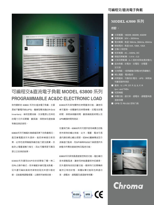
圖 3: 實際 RLC 線路
圖 4: 模擬 RLC 模式
圖 5: 定電流模式
直流負載模擬
63800 直流負載模擬包括四種負載模式 : 定電流、定電阻、定電壓及定功率模式,如下所述。
定功率 ■ 交流負載 : 一般負載模式與整流性負載模式 ■ 類比電壓、電流監控 ■ 時間量測 : 可應用於電池、UPS、保險絲
和斷路器等測試 ■ 量測 : V, I, PF, CF, P, Q, S, F, R
Ip+/- and THDv ■ 短路模擬 ■ 保護功能 : 過功率、過電流、過電壓與過
溫度保護 ■ GPIB 及 RS-232 控制介面
Programmable AC&DC Electronic load
致茂最新的 63800 系列交/直流電子負載,主要 是給不斷電系統(UPS)、離線型變流器(Off-Grid Inverters)、車用型變流器、交流電源以及其他 的電力元件如開關、斷路器、保險絲和連接器 等產品測試使用。
63800系列可模擬於高峰值因素下的負載情況, 甚至當電壓波形失真時,能即時補償功率因 素。此特性使得模擬負載的能力更加真實,亦 能防止電壓過應力發生,因此可獲得更可靠及 更公正的測試結果。
圖 7 : Off-Line UPS 轉換時間
自動頻寬調整 (ABA)
傳統的交流電子負載僅能操作於固定的拉載頻寬之下。若此電子負載屬於低頻寬特性,在模擬高峰值因素的負載時將會有所限制。反 之,屬於高頻寬特性的,若待測物的輸出阻抗高時,則會影響電流拉載的穩定度,甚至震盪。為解決此問題,63800系列交/直流負載可 藉由自動偵測待測物的輸出阻抗(註1),動態調整其操作頻寬,以減低系統不穩定的問題。
电子负载仪的使用
電子負載儀的使用用來測試評估/直流電源供應器之規格特性,蓄電池之奪命特性等用途(電子負載模組)。
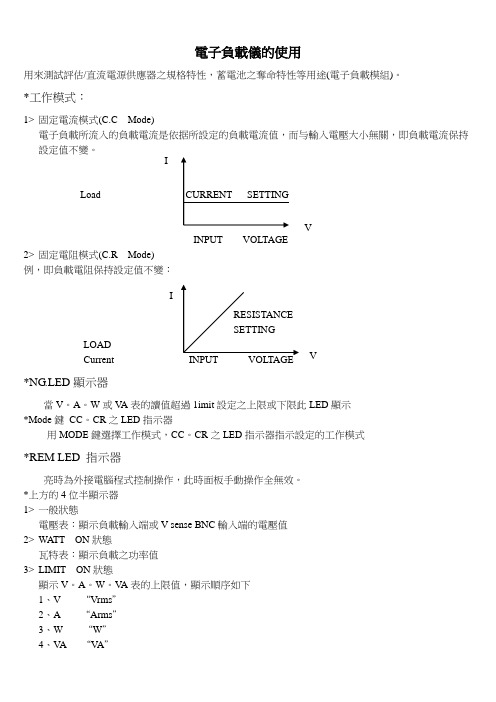
*工作模式:1> 固定電流模式(C.C Mode)電子負載所流入的負載電流是依据所設定的負載電流值,而与輸入電壓大小無關,即負載電流保持設定值不變。
LoadINPUT VOLTAGE2> 固定電阻模式(C.R Mode)例,即負載電阻保持設定值不變:LOADCurrent *NG .LED 顯示器當V 。
A 。
W 或V A 表的讀值超過1imit 設定之上限或下限此LED 顯示*Mode 鍵 CC 。
CR 之LED 指示器用MODE 鍵選擇工作模式,CC 。
CR 之LED 指示器指示設定的工作模式*REM LED 指示器亮時為外接電腦程式控制操作,此時面板手動操作全無效。
*上方的4位半顯示器1> 一般狀態電壓表:顯示負載輸入端或V sense BNC 輸入端的電壓值2> WATT ON 狀態瓦特表:顯示負載之功率值3> LIMIT ON 狀態顯示V 。
A 。
W 。
V A 表的上限值,顯示順序如下1、V “Vrms ”2、A “Arms ”3、W “W ”I VV I4、V A “V A”4>于保護狀況產生時過電壓保護時顯示“OVP”5>FREQ ON狀態顯示FREQ BAN Syne三种功能設定其顯示順序如下“1、頻率設定功能下“FREQ”2、波形庫選擇功能下“BAN”3、同步信號選擇功能下“SYNC”*下方的4位半顯示器1>PRESET OFF狀態電流表:顯示實際流入負載內的負載電流2>PRESET ON狀態顯示前面板手動操作之設定值或遙控時之設定值PRES“ON”:顯示CC。
Mode下的固定電流LEVEL A与B設定值“Arms”顯示CC。
Mode下的固定電流LEVEL A与B設定值“Ω”于保護狀況產生時,過“C”過“P”及過“T”時,分別會顯示“OCP”“OPP”及“OTP”3>LIMIT ON狀態電壓表之下限值:“Vrms”電流表之下限值:“Arms”瓦特表之下限值:“W”V A之下限值:“V A”4>REQ ONF:頻率設定功能下:顯示DC-99.9、100-999波形庫選擇功能下:顯示0-10同步信號選擇功能下:顯示“ON”或“OFF”*PRES ON/OFF鍵1>PRES按ON按OFF按ON按OFF按依此類推2>“ON”:預先設定狀況“OFF”:非預先設定狀況,而為實際負載之電壓電流狀況。
电子负载使用指导书

PRODIGIT目录目录第一章、概论 (3)1.1整体说明 (3)1.23310C系列电子负载之特性 (8)1.3附件 (8)1.4规格 (9)1.5系统方块图 (11)第二章、装机 (12)2.1装入及拔出3310C系列电子负载 (13)2.2电子负载模组的操作流程 (14)第三章、操作 (15)3.1操作说明 (16)3.23310C系列电子负载模组的起始设定参数 (23)3.3负载输入连接器与连接引线之考虑事项 (24)3.4负载电流粗调、微调,增量及减量调整 (25)3.5I MONITOR (输出) (27)3.6保护特性 (28)第四章、应用 (29)4.1本地电压检知连接法 (29)4.2远地电压检知连接法 (30)4.3固定电流模式(C.C. MODE)的应用 (31)4.4固定电阻模式(C.R. MODE)的应用 (33)4.5固定电压模式(C.V. MODE)的应用 (34)4.6固定功率模式(C.P. MODE)的应用 (35)4.7多组输出之电源供应器与电子负载之连接 (36)4.8并联操作 (37)目录PRODIGIT 图形图1.13310C0-60V/0-30A150W电子负载功率曲线图 (3)图1.23311C0-60V/0-60A300W电子负载功率曲线图 (3)图1.33312C0-250V/0-10A300W电子负载功率曲线图 (4)图1.43314C0-500V/0-5A200W电子负载功率曲线图 (4)图1.53315C0-60V/0-15A75W电子负载功率曲线图 (4)图1.6固定电流模式特性图 (5)图1.7固定电阻模式特性图 (5)图1.8固定电压模式特性图 (6)图1.9固定功率模式特性图 (6)图1.10动态负载模式特性图 (7)图1.113310C系列电子负载之方块图 (11)图2.1负载输入连接器与固定镙丝 (12)图2.2电子负载装入及拔出 (13)图2.33310C系列电子负载操作流程图 (14)图3.1前面板图 (15)图3.2典型的3310C系列电子负载连接方式 (21)图3.3负载电流之类比设定输入 (22)图4.1本地/远地电压检知连接图 (29)图4.2远地电压检知连接图 (30)图4.3固定电流操作模式之应用 (31)图4.4动态负载电流 (32)图4.5固定电阻操作模式之应用 (33)图4.6固定电压操作模式之应用 (34)图4.7固定功率操作模式之应用 (35)图4.8多组输出电源供应器与电子负载之连接图 (36)图4.9电子负载多组并联之连接图 (37)表格表1.13310C系列电子负载规格表 (9)表1.13310C系列电子负载规格表(续) (10)表3.13310C起始状态设定 (23)表3.23311C起始状态设定 (23)表3.33312C起始状态设定 (23)表3.43314C起始状态设定 (24)表3.53315C起始状态设定 (24)表3.6负载电流按键粗调/微调及不同档位之解析度 (266)PRODIGIT第一章概论第一章、概论1.1整体说明3310C 系列电子负载是用来测试估估直流电源供应器之规格特性,蓄电池之寿命特性以及电子元件之规格等用途。
电子负载使用说明书
目录第一章、概论 (3)1.1 整体说明 (3)1.2 3310C 系列电子负载之特性 (8)1.3 附件 (8)1.4 规格 (9)1.5 系统方块图 (11)第二章、装机 (12)2.1 装入及拔出3310C 系列电子负载 (13)2.2 电子负载模组的操作流程 (14)第三章、操作 (15)3.1 操作说明 (16)3.2 3310C 系列电子负载模组的起始设定参数 (23)3.3 负载输入连接器与连接引线之考虑事项 (24)3.4 负载电流粗调、微调,增量及减量调整 (25)3.5 Imonitor (输出) (27)3.6 保护特性 (28)第四章、应用 (29)4.1 本地电压检知连接法 (29)4.2 远地电压检知连接法 (30)4.3 固定电流模式(C.C. mode)的应用 (31)4.4 固定电阻模式(C.R. mode)的应用 (33)4.5 固定电压模式(C.V. mode)的应用 (34)4.6 固定功率模式(C.P. mode)的应用 (35)4.7 多组输出之电源供应器与电子负载之连接 (36)4.8 并联操作 (37)图形图1.1 3310C 0-60V / 0-30A 150W 电子负载功率曲线图 (3)图1.2 3311C 0-60V/0-60A 300W 电子负载功率曲线图 (3)图1.3 3312C 0-250V/0-10A 300W 电子负载功率曲线图 (4)图1.4 3314C 0-500V/0-5A 200W 电子负载功率曲线图 (4)图1.5 3315C 0-60V/0-15A 75W 电子负载功率曲线图 (4)图1.6 固定电流模式特性图 (5)图1.7 固定电阻模式特性图 (5)图1.8 固定电压模式特性图 (6)图1.9 固定功率模式特性图 (6)图1.10 动态负载模式特性图 (7)图1.11 3310C 系列电子负载之方块图 (11)图2.1 负载输入连接器与固定镙丝 (12)图2.2 电子负载装入及拔出 (13)图2.3 3310C 系列电子负载操作流程图 (14)图3.1 前面板图 (15)图3.2 典型的3310C 系列电子负载连接方式 (21)图3.3 负载电流之类比设定输入 (22)图4.1 本地/远地电压检知连接图 (29)图4.2 远地电压检知连接图 (30)图4.3 固定电流操作模式之应用 (31)图4.4 动态负载电流 (32)图4.5 固定电阻操作模式之应用 (33)图4.6 固定电压操作模式之应用 (34)图4.7 固定功率操作模式之应用 (35)图4.8 多组输出电源供应器与电子负载之连接图 (36)图4.9 电子负载多组并联之连接图 (37)表格表1.1 3310C 系列电子负载规格表 (9)表1.1 3310C 系列电子负载规格表(续) (10)表3.1 3310C 起始状态设定 (23)表3.2 3311C 起始状态设定 (23)表3.3 3312C 起始状态设定 (23)表3.4 3314C 起始状态设定 (24)表3.5 3315C 起始状态设定 (24)表3.6 负载电流按键粗调/微调及不同档位之解析度 (266)精品第一章、 概论1.1 整体说明3310C 系列电子负载是用来测试估估直流电源供应器之规格特性,蓄电池之寿命特性以及电子元件之规格等用途。
査察高科 loader 6310A 系列说明书
programmable parameters include: slew rate, load level, duration and conducting voltage. In addition, up to 100 sets of system operating status can be stored in EEPROM and recalled instantly for automated testing applications.Real time measurement of voltage and current are integrated into each 6310A load module using a 16-bit precision measurement circuit. The user can perform on line voltage measurements and adjustments or simulate short circuit test using the user friendly keypad on the front panel. Additionally, the 6310A series offers an optional remote controller for automated production lines.The 6310A series has a self-diagnosis routines to maintain instrument performance. It also provides OC, OP , OT protection, and alarm indicating OV, reverse polarity to guarantee quality and reliability for even in the most demanding engineering testing and ATE applications.PROGRAMMABLE DC ELECTRONIC LOAD MODEL 6310A SERIESThe Chroma 6310A series Programmable DC Electronic Load is ideal for the test and evaluation of multi-output AC/DC power supplies, DC/DC converters, chargers and power electronic components. It is designed for applications in research and development, production, and incoming inspection. The system is con gured by plugging the user selectable load modules into the system mainframe. The user interfaces include an ergonomically designed user friendly keypad on the front panel and the following computer interfaces: RS-232C, USB or GPIB.The 6310A series offers 12 different modules with power ratings from 20 watts to 1,200 watts, current ratings from 0.5mA to 240A, and voltage ratings from 0.5mV to 600V. The loads can be operated in constant current, constant voltage, constant power and constant resistance and may be placed in parallel for increased current and power.The 6310A series can simulate a wide range of dynamic loading applications. The waveformsProgrammable DC Electronic LoadC h ro m a 6310APro gra m m a b l e E l e c t ro n i c Lo a d i nte grate s microprocessor capabilities into each load module and mainframe to provide simple and accurate parallel operation to optimize the speed and control among multiple load modules. All load modules may be configured to work synchronously, to test multiple outputs simultaneously, thus simulating real life applications.The 6310A load modules operate in constant current, constant voltage,constant power or constant resistance to satisfy a wide range of test requirements. For example, the test of a battery charger can be simulated easily by setting the load to operate in constant voltage.APPLICATION OF SPECIFIC LOAD SIMULATIONThe 6310A series load modules will be compatible with the 6310 series mainframes (6312/6314). In addition, the remote control commands will be compatible between the 6310 and the 6310A series without needing to re-writing any remote control programs.COMPATIBILITY WITH 6310 SERIESMODULE LOAD DESIGN8-channel 100W/channel load with standard front-panel inputs. This makes it ideal for testing multiple output switching power supplies and multiple DC-DC converters. There are also higher wattage modules that may be mixed and matched for an even more versatile system. Additionally, the GO/NG output port is useful for UUT's pass/fail testing on an automated production line. All modules on the 6314A/6312A mainframe share a common GPIB address to synchronize and speed up the control of the load modules and the read-back of data.The Chroma 6314A 1400W and 6312A 700W electronic load mainframes accept the user-installable 6310A series load modules for easy system configuration and will mount in a 19" instrument rack. The6314A holds up to four 63102A load modules, which will result in anEach load module is designed with state-of-the-art technology and connects all the power MOSFET devices in parallel to insure high accuracy load control with a minimum drift of less than 0.1%+0.1%F.S. of the current setting. Chroma's use of FET technology provides minimum input resistance and enables the load to sink high current even at very low voltages. For example, the model 63123A is capableof sinking 70A at 0.6V, and well-suited for testing the new 3.3V low voltage power supplies. Low voltage operation, down to zero volts, is possible at reduced current levels.The 6310A load module uses a photo coupler for isolation between the output and control sections, thus each load is isolated and floating. The user can use multiple load modules independently to test multi-output power supplies, or parallel them for high power testing applications.DYNAMIC LOADING AND CONTROLModern electronic devices operate at very high speeds and require fast dynamic operation of their power providing components. To satisfy these testing applications, the 6310A loads offer high speed, programmable dynamic load simulation and control capability. The figure aside shows the programmable parameters of the 6310A modules:The programmable slew rate makes the simulation of transient load change demanded by real life applications possible. The 6310A internal waveform generator is capable of producing a maximum slew rate at 10A/µs, and dynamic cycling up to 20kHz. It's dedicated remote load sense and control circuit guarantee minimum waveform distortion during continuous load changes.MULTI CHANNEL CONTROLThe 6310A comes with RS-232C as standard for remote control and automated testing applications. The USB and GPIB interfaces are available as options. In addition, the 6310A provides an efficient solution for testing single output AC to DC or DC to DC converters by controlling multiple loads. The 6310A provides the capability to test upto 8 UUTs at a time.UUT : AdaptorThe 6310A series of loads include a unique timing & measurement function, which allows precise time measurements in the range of 1ms to 86,400s. This feature allows the user to set the final voltage & timeout values for battery discharge testing, super capacitor discharge, and other similar applications.For example, the figure on the right shows the 6310A internal timer starting at Load ON, and ending when the battery voltage reaches the final voltage.The digital I/O interface makes the 6310A DC Load the ideal choice for automated testing requirements. Through the digital I/O, the 6310A can accept digital signals to trigger its functions (Load On/Off, OCP test, etc.) as well as current output status signals.Each 6310A load module has an integrated 16-bit precision A/D converter for voltage measurement with an accuracy of 0.025%+0.015%* of full scale. The built-in resistive load current sensing circuit is capable of measuring current with an accuracy of 0.04%+0.04%* of full scale. Apart from voltage and current measurement, 6310A also provides power measurement function and there is no need for users to spend time for power calculation. Also, short circuit can be simulated. All measurements are done using remote sensing to eliminate any error due to voltage drops along the measurement path. The user can also select from a complete set of voltage and current measurements.Note * : Only for Model 63123AModern switching power supplies are designed with over current protection (OCP) circuitry; therefore, it is important to test the OCP circuitry to make sure it is functioning within its designed specifications. The 6310A series provides an easy and fast solution for this testing.By simply choosing the channel and setting the OCP parameters (start current, end current, step current and dwell time) from the front panel, the 6310A series provides a fast and easy OCP testing solution. The 6310A series will automatically detect the OCP point, making it an ideal solution for design verification as well as production line testing.Battery Discharge Testing6314A : 4 in 1 Mainframe A631001:Remote ControllerA631000 :GPIB Interface63106A / 63108A63102A / 63107A / 63110A63101A63105A63112A63103A / 63123A /63113A / 63115A6312A : 2 in 1 Mainframe A631003 :USB InterfaceAs a constant current source, the LED power driver has an output voltage range with a constant output current. LED power drivers are usually tested in one of the following ways :1. With LEDs2. Using resistors for loading3. Using Electronic Loads in Constant Resistance (CR) mode, or Constant Voltage (CV) mode However, all these testing methods, each of them has their own disadvantages.As shown on the V-I curve in Figure 1, the LED has a forward voltage VF and a operating resistance (Rd). When using a resistor as loading, the V-I curve of the resistor is not ableto simulate the V-I curve of the LED as shown in blue on Figure 1. This may cause the LED power driver to not start up due to the difference in V-I characteristic between the resistors and the LEDs. When using Electronic Loads, the CR and CV mode settings are set for when the LED is under stable operation and therefore, is unable to simulate turn on or PWM brightness control characteristics. This may cause the LED power driver to function improperly or trigger it's protection circuits. These testing requirements can be achieved when using a LEDs as a load; however, issues regarding the LED aging as well as different LED power drivers may require different types of LEDs or a number of LEDs. This makes it inconvenient for mass production testing.Chroma has created the industries first LED Load Simulator for simulating LED loading with our 63110A load model from our 6310A series Electronic Loads. By setting the LED power driver's output voltage, and current, the Electronic Load can simulate the LED's loading characteristics. The LED's forward voltage and operating resistance can also be set to further adjust the loading current and ripple current to better simulate LED characteristics. The 63110A design also has increased bandwidth to allow for PWM dimming testing.Figure 4 shows the dimming current waveform of the LED.Figure 5 shows the dimming current waveform when using 63110A as a load.Figure 1 - LED V-I characteristicsFigure 5 - 63110A dimming test Figure 6 - LED driver turn-on waveformFigure 4 - LED dimming test Figure 3 - Simulate different characteristic of LEDsFigure 2 - Simulate different number of LEDsRear Panel18 ON/OFF key : To enable or disable the load input 19 Up/Down key : To select the next or previous displayin edit mode20 Numeric key : For data setting21 ENTER key : To confirm editing data on the instrument 22 SHIFT key : As LOCAL key when in remote mode 23 Power switch24 SHIFT + 0 key : System function 25 SHIFT + . key : Lock function26 SHIFT + 3 key : Clear the currently edited data27 Digital I/O : Used for system input/output control signals 28 RS-232C connector 29 GO/NG output port 30 GPIB or USB slot31 AC input voltage switch 32 AC input fuse33 AC input connector1 LED indicator2 SHORT key : To apply a short circuit across the input3 STATIC/DYNA key : To select static or dynamic test mode4 L/R key : To select left or right channel of input load(63102A, 63107A) A/B key : To select static A or B load (other models)5 V terminal : To measure the UUT's output voltage using remote sense6 Rotary knob : To adjust load setting continuously7 Load terminal8 LCD display9 LED indicator : To display the channel at which load is set 10 CHAN key : To select input load channel11 MODE key : To select the operation mode of CC, CR, CV or CP 12 PROG key : For program data setting13 OCP/OPP key : Over current protection/Over power protection testing 14 RECALL key : To recall the front panel input status from memory 15 SAVE key : To save the front panel input status into memory 16 SPEC key : To set up High/Low limits for GO/NG test 17 CONF key :To set the configurationLoad ModuleMainframe ControllerNOTE*2 : S (siemens) is the SI unit of conductance, equal to one reciprocal ohm. NOTE*3 : Call for availability• Continued on next page ➟NOTE*1 : Low voltage operation, under 0.8 volt, is possible at correspondingly reduced current level. Operating temperature range is 0˚C to 40˚C. All specifications apply for 25˚C 5˚C, except as notedit would cause permanent damage to the device.NOTE*4 : Please refer to user's manual for detail specifications.NOTE*5 : S (siemens) is the SI unit of conductance, equal to one reciprocal ohm. NOTE*6 : The loading current should be 0.35A at least.6310A-E-201310-2000Worldwide Distribution and Service NetworkJAPANCHROMA JAPAN CORP .472 Nippa-cho, Kouhoku-ku, Yokohama-shi, Kanagawa,223-0057 JapanTel: +81-45-542-1118Fax: +81-45-542-1080http://www.chroma.co.jp E-mail:******************U.S.A.CHROMA SYSTEMS SOLUTIONS, INC.19772 Pauling, Foothill Ranch, CA 92610Tel: +1-949-600-6400Fax: +1-949-600-6401 E-mail:*******************Developed and Manufactured by :CHROMA ATE INC.HEADQUARTERS66 Hwaya 1st Rd., Kueishan Hwaya Technology Park,Taoyuan County 33383,TaiwanTel: +886-3-327-9999Fax: +886-3-327-8898 E-mail:******************EUROPECHROMA ATE EUROPE B.V.Morsestraat 32, 6716 AH Ede,The Netherlands Tel: +31-318-648282Fax: +31-318-648288 E-mail:******************CHINACHROMA ELECTRONICS (SHENZHEN) CO., LTD.8F, No.4, Nanyou Tian An Industrial Estate, Shenzhen, China PC: 518052Tel: +86-755-2664-4598Fax: +86-755-2641-96206312A : Mainframe for 2 Load Modules 6314A : Mainframe for 4 Load Modules 63101A : Load Module 80V/40A/200W 63102A : Load Module 80V/20A/100W x 263103A : Load Module 80V/60A/300W 63105A : Load Module 500V/10A/300W 63106A : Load Module 80V/120A/600W63107A : Load Module 80V/5A & 40A/30W & 250W 63108A : Load Module 500V/20A/600W 63112A : Load Module 80V/240A/1200W 63123A : Load Module 120V/70A/350WA631000 : GPIB Interface for Model 6314A/6312A Mainframe A631001 : Remote ControllerA631003 : USB Interface for Model 6314A/6312A Mainframe A631005 : Softpanel for 6310A/6330A seriesA631006 : Rack Mounting Kit for Model 6312A Mainframe A631007 : Rack Mounting Kit for Model 6314A Mainframe A800042 : Test FixtureLED Load Simulator for LED Driver Test 63110A : Load Module 500V/2A/100W x 263113A : Load Module 300V/20A/300W * 63115A : Load Module 600V/20A/300W * Call for availabilityORDERING INFORMATIONThe 6310A loads can be operated from the front panel controls of mainframe or from available softpanels. This user friendly software includes all functions of 6310A and is easy to understand and operate. The 6310A can be controlled via GPIB and USB interfaces for remote control and automated testing applications.LED Mode Dynamic Test Battery Test Charger Test。
Keithley 63200A高功率电子负载产品介绍说明书
GPIBEthernet USBChroma's 63200A series high power electronic loads with digital signal microprocessor (200MHz) built in have the optimal speed and control performance. The ultra high density power (6kW@4U) not only saves room, its super high voltage (0.015%+0.015%F.S.) and current (0.04%+0.04%F.S.) measurement accuracy ensures the fidelity of results. In addition, the entire series can either be operated by hand or controlled remotely. For higher power demands, master/slave control can be used to parallel multiple units for operation. These electronic loads also have synchronous loading capabilities to simulate the actual loading status.Data Center Server PowerHigh Voltage UPSTelecom PowerBattery PackSolar Panel Energy Storage System On Board ChargerEV Charger StationThe iconic function selections make it easier for users to control/operate the 63200A series. The basic and advance functions are iconized, users can select the functions via the rotary or arrow keys. The abbreviations are shown in the icons and the full descriptions are shown on the VFD display for users to easily operate without the need for an operation manual.ICONIC FUNCTION SELECTIONSThe world leading ultra high power density design overturns the concept of oversize and difficult moving high power electronic load. It saves plenty of room space and solves the space issue when upgrading the electronic load in an automated test system. Moreover, the 63200A provides 4 sets of user-defined hot keys that enable the user to enter the operation mode quickly.The 63200A series electronic loads operate in constant voltage, current, resistance, or power modes to satisfy a wide range of test requirements. For instance, the CC and CR modes ensure that the UUT voltage outputs remain stable when the load varies. For battery chargers or charging stations, CV mode can change their output voltage to ensure the precision of the charging current. When the UUT is a battery, the electronic load changes to simulate device loading behavior. Many battery discharge applications and power consumption profiles can be simulated for analysis, making the CP mode the best choice for simulating electronic device loads.APPLICATION OF BASIC LOADSCC Mode CR Mode CV Mode CP Mode The 63200A series is equipped with flippable front panel for 7U, 10U & 13U height models with maximum flippable angles 70˚. This design allowsconvenient access to controls from any height.MASTER/SLAVE PARALLEL CONTROLWhen the need is for increased power, two or more loads can be run in parallel to achieve the desired load current. The 63200A provides the user with smart Master/ Slave mode controls which enables the user to program the load currents of the Master and have them automatically calculated and downloaded to the slave loads. Using several loads in parallel to emulate a single load dramatically simplifies the operation. All models of the series can be integrated into a 41U standard rack to save space. The 63200A can be controlled and reconfigured with automatedtesting applications via standard USB or optional Ethernet and GPIB interfaces.Model 63200A Series Load63224A-150-2000The 63200A series has a unique sine wave loading function which allows setting of a current bias (I_DC), a loading sine wave (I_AC) and sine wave frequency. The sine wave loading must be greater or equal to zero ampere. This function can be used for D/D, server power supplies and fuel cells for DCIR testing.The dynamic mode provides a unique simulation capability allowing users to set the number of times each cycle repeats from 1~65535. This feature is very suitable for testing D/D converter and instant large withstand current of batteries.Modern electronic devices operate at very high speeds and demand rapid transient response characteristics. To address these applications, the 63200A series offers high speed, programmable dynamic loading (CCD: Dynamic Current Loading & CRD: Dynamic Resistance Loading) and sweep simulation for testing. The figure shown below exhibits the programmable parameters such as current high/low level, T1/T2, rise/fall rate and execution times. When the load current changes continuously, the internal monitoring mechanism and line circuit can minimize the current waveform distortion. The current rise minimum response time for model150V is 10µs and the dynamic change is up to 50kHz.There are many capacitors on the mainboard of PC. To prevent the inrush current from occurring and trigger the over current protection of server power (since the server power charges the capacitors on the mainboard). It is necessary to test the capacitive loading when turning on the power supply. Therefore, the 63200A series provides the CZ mode for this test.The unique CZ mode designed in 63200A series can improve the loading behavior of CC & CP mode and makes the simulatedloading current more realistic.The 63200A also offers a unique dynamic frequency sweep (as shown on the right) with variable frequencies up to 50kHz. This capability is ideal for determining worst case voltage peaks. Measurement of the Vpeak (+/-) can be achieved using this function with a sampling rate of 500kHz. The dynamic loading mode can simulate different loading conditions for most test requirements. Dedicated remote load sensors and control circuits guarantee minimum waveform distortion during dynamic loading.In addition to common CC, CV, CP and CR loading modes of conventional loads, the 63200A accepts digital data from DAQ cards or analog data from function generators to allow for complex waveforms to be created as depicted below.OCP TestThe 63200A also provides an enhanced feature, User Defined Waveform (UDW), to simulate the actual current profiles and waveforms. To reconstruct the actual current waveform, the user can upload captured waveform data into any load via a Chroma softpanel. Each load is capable of storing up to 10 sets of waveforms with each comprising up to 1.5 millions data points to meet the more strenuous test requirements.In addition, 63200A series also provides voltage peak measurement during actual loading conditions. Avoiding the need for using an oscilloscope to capture the voltage peak, saving time and costs.Function GeneratorTo ensure user safety and minimize power supply failure rates, overcurrent and overpower protections have to be taken into consideration during design. The 63200A enables the user to set current and power orders to test overcurrent and overpower protections, also to judge the test result as Pass or Fail on electronic load. The maximum power (Pmax) during testing can be captured and showed on the display without using an oscilloscope to verify the correctness of designed overcurrent and overpower . It can save a lot of testing time for the user.The 63200A series provides three operating and measuring ranges. Take 63206A-150-600 for example, three voltage ranges of 16V/80V/150V which can meet the requirements of server power or telecom power (12V, 48V, 54V) testing; three current ranges of 60A/300A/600A which can provide different applications of current operating and can minimize the measurement error by selecting the suitable range. Besides, a built-in highly precision A/D converter, achieving 0.015%+0.015%F.S., 0.04%+0.04%F.S. and 0.1%+0.1%F.S. accuracy for voltage, current and power measurement espectively. Precise measurements like these are ideal for testing power efficiency and other critical parameters of the UUT's.DAQTrig. V OCP/OPPDwell timeDIGITIZING FUNCTIONThe 63200A series electronic load has built in 255 programmable timings for various loading conditions simulation. Following lists the applications of common programmed timings.The 63200A series offers a digitizing function convenient for the recording of transients in both voltage and current waveforms. The following are the specifications for setting the parameters:Sampling time : 2µs ~ 40ms / resolution: 2µs (Setting the interval of sampling time)Sampling point : 1 ~ 15,000 (Setting the total sampling points)1. Battery discharge & other applications (NPC, electric car and electric locomotive) to simulate various dynamic loading current waveform, that is to provide two levels above dynamic current simulation or one shot loading simulation.2. Server/ Telecom power supply mixed load modulation. (For multi channels output UUT.)Battery Discharge TestingThe 63200A has three discharge modes: CC, CR and CP . The electronic load can set cut off voltage and time (1~100,000 sec.) to stop loading correctly and make sure the battery is not damaged due to over discharge. In addition it can measure the battery discharge power (WH, AH) and total discharge time. For example, when Load ON is pressed, the 63200A internal clock will start counting until the battery voltage is dropped to cut off voltage or Load OFF ispressed. The battery discharge testing can also apply to super capacitor for discharge time testing and so on.This mode automatically switches among CV, CR, CC and CP modes. It is suitable for lithium ion battery charger testing to get a complete V-I charging curve. Moreover, the auto mode can avoid damaging the UUT when the protection circuit is damaged.The 63200A series loads can be operated from the front panel controls or from available softpanel. This user friendly software includes all functions of the 63200A series loads and is easy to understand and operate. The 63200A loads can be controlled via GPIB, USB and Ethernet interfaces for remote control and automated testing applications.MainBattery DischargeOver Current Protection Sine WaveProgramUser Defined WaveformNew complex operating modes include CR+CC, CV+CR and CV+CC modes. The CR+CC mode is suitable for power on testing and the CV+CR mode canreplace Von setting while the CV+CC mode can be used for battery discharge testing.I/V Curve I/V Curve I/V Curve CR+CC ModeCV+CR ModeCV+CC Mode9. Load Positive/Negative Terminal 10. Remote Sense Connections11. Analog Outputs : Proportional voltage and current waveforms 12. System BUS : For master/slave system data transmission 13. System I/O : For system input/output signal control 14. GPIB & Ethernet Card Slot 15. USB Port16. AC Input Connector1. Power Switch : Electronic load AC power switch2. Vacuum Fluorescent Display : Setup information display3. Shortcut Keys : Loading mode switch4. Function Keys : Including A/B key, RANGE, MODE, EXTEND, LOCK, COFIG./LOCAL, EDIT, SPEC, SHORT, RECALL, ADVA, SAVE & CLEAR5. ENTRY Keys : Numerical keys and ENTER key6. Arrow Keys : Changing and selecting menu7. Push-on Knob : Editing parameter setup page, push the knob again to confirm the input value when the setting is done 8. USB Host (not ready yet): For user defined waveform and programmed sequence data download as well as firmware upgrade• Continued on next page ➟• Continued on next page➟• Continued on next page ➟ORDERING INFORMATION1. The specifications are guaranteed to meet specified performance at temperature range of 25 5˚C.2. If the operating voltage exceeds the rated voltage for 1.05 times, it would cause permanent damage to the device.3. The power rating specifications at ambient temperature = 25˚C.4. If the operating current is below range 0.2%, the accuracy specification is 0.1% F.S.5. Power F.S. = Vrange F.S.x Irang F.S.6. The specification is valid only for loading current > 4% F.S.7. The short circuit function simulates full power loading and thus it cannot perform mechanical short circuit.63200A-E-201605-pdfJAPANCHROMA JAPAN CORP .888 Nippa-cho, Kouhoku-ku, Yokohama-shi, Kanagawa,223-0057 Japan T +81-45-542-1118F +81-45-542-1080www.chroma.co.jp **************.jpU.S.A.CHROMA SYSTEMS SOLUTIONS, INC.19772 Pauling, Foothill Ranch, CA 92610T +1-949-600-6400F + *******************EUROPECHROMA ATE EUROPE B.V.Morsestraat 32, 6716 AH Ede,The Netherlands T +31-318-648282F + ******************CHINACHROMA ELECTRONICS (SHENZHEN) CO., LTD.8F, No.4, Nanyou Tian An Industrial Estate, Shenzhen, China PC: 518052T +86-755-2664-4598F +86-755-2641-9620 ******************SOUTHEAST ASIA QUANTEL PTE LTD.(A Company of Chroma Group)46 Lorong 17 Geylang # 05-02 Enterprise Industrial Building,Singapore 388568T +65-6745-3200F +65-6745-9764 ***********************.comHEADQUARTERS CHROMA ATE INC.66 Huaya 1st Road,Guishan, Taoyuan 33383, TaiwanT +886-3-327-9999F + ******************63204A-150-400 : High Power DC Electronic Load 150V / 400A/ 4kW 63205A-150-500 : High Power DC Electronic Load 150V / 500A / 5kW 63206A-150-600 : High Power DC Electronic Load 150V / 600A / 6kW 63224A-150-2000 : High Power DC Electronic Load 150V / 2000A / 24kW 63204A-600-280 : High Power DC Electronic Load 600V / 280A / 4kW 63205A-600-350 : High Power DC Electronic Load 600V / 350A / 5kW 63206A-600-420 : High Power DC Electronic Load 600V / 420A / 6kW 63224A-600-1680 : High Power DC Electronic Load 600V / 1680A / 24kW 63204A-1200-160 : High Power DC Electronic Load 1,200V / 160A / 4kW 63205A-1200-200 : High Power DC Electronic Load 1,200V / 200A / 5kW 63206A-1200-240 : High Power DC Electronic Load 1,200V / 240A / 6kW 63224A-1200-960 : High Power DC Electronic Load 1,200V / 960A / 24kW A600009 : GPIB cable (200cm)A600010 : GPIB cable (60cm)A632000 : Softpanel for 63200A SeriesA632006 : NI USB-6211 Bus-Powered Multifunction DAQ A636000 : GPIB interface A636010 : Ethernet interface。
嘉拓电子负载超强功能
1. 可编程电流上升率目前市面上的大部分电子负载(非模组式)都没有此项功能。
此项功能是动态测试的基本要求。
嘉拓JT63系列电子负载创新具有此功能。
2. 最小满量程电流上升时间这项功能是电子负载的核心指标,直接反应电子负载的速度。
就如电脑的CPU,直接影响电脑的速度。
目前市面上最快的最小满量程电流上升时间为25uS,如chroma 6310/6330系列,艾德克斯IT85系列为40uS。
速度而嘉拓JT63系列电子负载此项指标仅为10uS。
反应速度极快。
3. 纹波量测,大部分负载都不能测量纹波,需要测量纹波的客户只能买示波器来满足此项要求。
多花钱买一样产品不说,示波器操作专业化程度高,操作繁杂,测试时间长,且对个人主观依赖大,不够客观。
嘉拓电子JT63系列电子负载借助500kHz同步采样技术,可以摆脱示波器,实现纹波量测。
4.Vp+/Vp- 电压峰值、谷值测量此项指标是测试开关电源瞬态测试的必测内容。
嘉拓电子负载创新的支持Vpp/Ipp实时显示,直接观察PARD或震荡幅度。
Vp+/Vp-/Ip+/Ip-实时显示,直接观察电压过冲与跌落、电流浪涌 Vp+/Vp-实时显示,动态模式下,直接观察电压过冲与跌落,判定电不良。
5.时序测试此项功能可测试多路电源开机时序,电源启动/保持/建立时间,电流通断时间等。
大部分负载都没有此项功能,需要借助时序测量卡来完成。
嘉拓JT63系列电子负载创新支持时序测量功能。
6.OCP测试及动态频率扫描大多数负载没有这项功能,致使测试起来效率很低。
嘉拓电子JT63系列电子负载借助DSP技术,可执行自动OCP测试、自动负载效应测试、自动动态变频扫描测试,提高测试效率。
7. OVP 测试大多数负载没有此项功能,需借助示波器来完成。
嘉拓电子JT63系列电子负载创新的支持过压保护点自动捕捉和uS级OVP响应时间量测。
8.数字化波形攫取嘉拓电子JT63系列电子负载创新支持500Khz,4096点,16位精度数字化波形输出电压电流同步采样多种触发方法支持9. 多机同步时序控制嘉拓电子JT63系列电子负载创新支持多达16台负载的同步动态带载,满足多路输出电源交叉影响测试;主机可以是任意一台负载,无需机框,实现低成本模组应用;通过一台主机的程序控制,即可实现16台负载的程序控制。
- 1、下载文档前请自行甄别文档内容的完整性,平台不提供额外的编辑、内容补充、找答案等附加服务。
- 2、"仅部分预览"的文档,不可在线预览部分如存在完整性等问题,可反馈申请退款(可完整预览的文档不适用该条件!)。
- 3、如文档侵犯您的权益,请联系客服反馈,我们会尽快为您处理(人工客服工作时间:9:00-18:30)。
Chroma 6310系列电子负载操作指导书1 前言和目的本文阐明了Chroma 6310系列电子负载操作方法,便于实际的操作使用。
2 适用范围适用于Chroma 6310系列电子负载的使用操作。
3 操作规程3.1仪器简介Chroma 6310系列电子负载6314插框可以放下四路电子负载,6312可以放下两路负载模块(63102、63103、63105、63107……),包括一个处理器,GPIB接口、RS-232接口、控制面板、以及显示器和PASS/FAIL信号。
具有SA VE/RECALL功能,可以储存100份文件,10个程序、一个缺省默认设计。
各路负载模块可以各自工作在CC、CR、CV 三种模式,每个模块都具有一个或者两个通道(63103、63106为当通道模块,63102、63107为双通道模块),每个通道都有自己的编号(1~8),可以各自独立地turn on/ turn off,或short-circuited。
如果一个模块带载不够还可以将模块并联提高带载能力,当四路都加载时最大功率可达1200W。
其中控制面板有三个键都可以实现两个功能,将SHIFT键与该键同时按下就可以实现另外一个功能。
3.2插框面板按钮介绍1.电源开关2.LCD显示器3.通道显示4.功能键CHAN:选定通道进行设置MODE:用来选择带载模式(CC、CR、CV)PROG:用来编辑一组带载程序或者运行一组带载程序。
CLEAR:当数字输入错误后,按该键可以清除。
RECALL:可以用来调用先前存储的负载设置。
SA VE:当你设置好一种负载后可以使用该键保存到一个程序里面(1to10),下次使用可以通过RECALL(1to10)调用。
存储/调用(SA VE/RECALL)该系列负载可以对各路负载设定值按顺序储存在一个文件里,下次再要用到该系列负载时可以将此文件调用出来,如你要将已经设定好好的负载值储存到1号文件里,则只需按SA VE,然后按方向键,当显示器出现SA VE PROGRAM 1:YES 2:NO时,按键“1”存储,当下次要再次调用该系列负载时,只需按RECALL,1,ENTER,则所有通道的设定值都回被条用出来,然后按LOAD即可加载。
SPEC:SPEC功能开关。
CONF:可以进行初始值CONF设置。
初始值设置Configuration按键CONF则弹出菜单CC Vrange Select 1:HIGH 2=LOW 设置模块带载端子电压范围选1则可以承受高电压,选2则电压范围小,超出范围模块报警。
ENTER,跳出设置带载点Von Point VOLTAGE:-V 在光标处输入加载点电压值,再ENTER,弹出V on Latch 1:ON 2:OFF 选1 一旦输出电压达到加载点Von Point开始加载,就算加载引起电压瞬间低于V on Point仍能继续加载,若选2则一旦电压被拉低小于加载点则马上卸载。
ENTER则出现CV. CURR-LIMIT CURRENT:-A 在光标处设置CV模式下的限流点。
ENTERSIGN OF VOLT 1:PLUS 2:MINUS 选1电压值为正选2为负,符合是“-”5.输入键上下方向键ON/OFF:负载带载卸载开关ENTER:回车键,设置参数后按该键确认写入SHIFT: 上档键,选择上档功能,或者在遥控状态下按该键可以转为本地面板操作。
0-9:数字键. :输入小数点3.3 负载模块面板按钮功能简介:1.7段LED显示2.模块通道LED显示(L/R):对于具有双负载通道的模块若标识R的LED亮,则右边标识R的通道使能,若标识L的LED亮,则左边标识L的通道使能,可以通过键R/L来切换。
对于单通道的模块63103、63106则没有该LED显示3.7段LED显示数值单位(电压/V,电流/A)4.带载模式与GO/NG显示:若检测不能满足SPEC设置,则GO/NG显示红灯,满足设置则显示绿灯。
5.键区显示灯6.键区:R/L 、STATIC/DYNAMIC 、SHORT 、LOAD ,当你按键后上方的LED 灯就会亮红灯,分别实现该负载(R 或者L )通道的动态负载、短路、带载功能。
对于模块加载卸载可以通过插框的主键盘的ON/OFF 键来进行加载/卸载,或者通过单个模块LOAD 键来控制。
有的模块如63102具有两路通道,左边的通道“L ”和右边的通道“R ”而这两个通道相互之间是隔离的,通过键“R/L ”可以切换。
当两个通道同时选择时,两个LED 等都亮,此时键STA TIC/DYNAMIC 、SHORT 、LOAD 操作不起作用。
对于单通道模块如右图则键区R/L 为键A/B ,A/B 键上LED 灯亮则灯亮选择的是A ,灯灭选择的是B ,选A 则是LEVEL1,选B 则是带载LEVEL2。
7.Vsense 端子:遥控操作的电压SENSE 端。
8.旋钮:功能相当于数字键,顺时针方向旋转数值增加,逆时针方向数值减小。
9.负载带载正负端子。
“+”极必须必须接“UUT ”的正,“-”接“UUT ”的地。
3.4 具体应用1、负载带载模式设置各路负载模块可以各自工作在CC 、CR 、CV 三种模式,更换负载模式只要通过“MODE ”键选定所需的负载模式然后按“ENTER ”键即可。
在更改模式的过程中,模块的输入自动关断以确保在切换负载时过冲最小CC.在CC 恒流模式下会根据你编辑的数值提供负载电流,不受输入电压的影响,CC 可由“MODE ”键设置,当“MODE SELECT ”字样在显示器上出现后,通过上下键,可以选定低负载范围“CCL ”或者是高负载范围“CCH ” ,设定动态负载跳变时可以选择低动态负载范围“CCDL ”或者是高动态负载范围“CCDH ”然后按“ENTER ”键即可。
CR在一定的CR下负载电流与输入电压成正比,在模块的输入端有一个双极性的RC滤波器,所以高频部分将会被滤掉,延迟时间大约为47uS,为防止由于输入电压的波动而带来负载电流的改变,电源阻抗必须尽量小,同时在大电流负载下必须使用遥控SENCE 电缆去检测输入电压。
CR模式下也可以选择“LOW RANGE”CRL和“HIGH RANGE”CRH两个负载范围,可以通过方向键来选取,其负载值设定与CC类似,CR无法设置动态负载跳变。
CV在CV下负载将会控制电源输出电压到编辑值,也可以通过A/B来选定两个不同的电压值。
可以设计响应速率,对于CV模式有FAST和SLOW两个响应速度。
2、将所有负载通道都设置为CC模式下5A负载按键STATIC/DYNAMIC使LED灯灭,使负载工作在稳态负载下,在某些模块内(63103)设计了两个稳态负载值(A或B),可以通过建A/B来切换,灯亮选择的是A,灯灭选择的是B,选A则是LEVEL1,选B则是带载LEVEL2。
按CHAN键选择你要设置的通道;按“MODE”,当“MODE SELECT”字样在显示器上出现后,通过上下键,可以选定高负载范围“CCH”然后按“ENTER”键即可。
这样就确定了CC模式。
然后通过方向键选到下一步设置,在CCH1、CCH2分别设置为5A,按数字键2,ENTER。
CCH1:5ACCH2:5A设置加载速率,按键0 . 1CCH(加载速率):0.1A/uSCCH(卸载速率):0.1A/uS一个负载通道负载值设置完毕,按键CHAN再设置下个通道的负载值,所有通道都设置完毕后按键SA VE可以将设置的负载保存到一个文件里,下次需要时又可以调用出来。
然后按键“1”SA VE FILEFILE NO:1将该所有通道的负载设置保存到文件1里面下次需要该负载设置时,重新调用,按键RECALL,“1”,ENTER则又可以将设置好的负载调用出来。
3、CC模式下设置动态负载值按CHAN键选择你要设置的通道;按“MODE”,当“MODE SELECT”字样在显示器上出现后,通过上下键,可以选定高动态负载范围“CCDH”然后按“ENTER”键即可,而动态负载需编辑两个负载值(CCDH1,CCDH2),两个加载时间(CCDHT1,CCDHT2),以及负载跳变斜率,静态/动态功能可以通过键STA TIC/DYNAMIC来切换。
当要设计电流值CCDH1为2A时,则可以按“2”键然后按“ENTER”,当要设计电流值CCDH2为4A时,则可以按“4”键然后按“ENTER”即可。
CCDH1:2ACCDH2:4A接着显示器会跳出变换时斜率大小值,若要修改为上升率为1A/uS以及下降速率为1A/uS,则对上升速率按“1”“ENTER”,对下降速率按“1”“ENTER”。
CCDH(加载速率):0.1A/uSCCDH(卸载速率):0.1A/uS对于动态负载跳变设计,动态还有一个各负载带载时间设定,如CCDHT1:2mS,CCDHT2:4mS,则分别按设定的值,然后再按ENTER即可。
CCDHT1:2mSCCDHT2:4mS然后按键CHAN则可切换负载模块,继续设置另一个通道模块的带载值。
所有通道都设置完毕后按键SA VE可以将设置的负载保存到一个文件里,下次需要时又可以调用出来。
然后按键“2”SA VE FILEFILE NO:2将该所有通道的负载设置保存到文件2里面下次需要该负载设置时,重新调用,按键RECALL,“2”,ENTER则又可以将设置好的动态负载调用出来使用。
按键STATIC/DYNAMIC,LED灯亮,LOAD ON开始输出设置好的动态负载,进行2A(2mS)~4A(4mS),1A/uS,的动态负载跳变。
CR、CV负载设置与CC类似,但是不能进行动态负载跳变。