stm32f103zet6串行驱动12864
stm32-12864并行驱动程序

//////////////////////////////////////////////////////////////////////////////////stm32-12864并行驱动程序////////////////////////////////////////////////////#include "delay.h" //必须配合delay.c 和delay.h 文件使用,所以要包含delay.h。
#include "display12864.h"f/********** 以下是相关引脚定义。
**************/// A 口的#define DisIO GPIOE //定义12864 要使用的I/O 端口。
#define DisClk RCC_APB2Periph_GPIOE //定义12864 要使用的I/O 端口的时钟。
#define DataGPIO_Pin_0|GPIO_Pin_1|GPIO_Pin_2|GPIO_Pin_3|GPIO_Pin_4|GPIO_Pin_5|GPIO_Pin_6|GPIO_Pin_7//定义12864 使用的数据引脚。
#define EN GPIO_Pin_10 //定义使能端使用的引脚/*********************************************/#define DisIOIO GPIOE //定义12864 要使用的I/O 端口。
#define DisClkIO RCC_APB2Periph_GPIOE //定义12864 要使用的I/O 端口的时钟。
#define RS #define RW GPIO_Pin_9GPIO_Pin_8/*光标定位函数定义结束。
*/#define x1 0x80#define x2 0x88#define y 0x80GPIO_InitTypeDef GPIOStru; //定义用于定义所以引脚为输出的变量。
STM32串行驱动12864液晶
STM32串⾏驱动12864液晶⾃⼰参考⼤神们的程序改写的液晶驱动,希望对有需要的⼈能有帮助#include "stm32f10x.h"static __IO uint32_t TimingDelay;void RCC_Configuration(void);void Delay(__IO uint32_t nTime);#define Line1 0x80//液晶第⼀⾏#define Line2 0x90//液晶第⼆⾏#define Line3 0x88//液晶第三⾏#define Line4 0x98//液晶第四⾏#define LCD_IO GPIOE //我⽤的是E.2 E.3 E.4 E.5 E.6#define CS GPIO_Pin_2#define RW GPIO_Pin_3#define CLK GPIO_Pin_4#define PSB GPIO_Pin_5#define RST GPIO_Pin_6#define SET(n) GPIO_SetBits(GPIOE,n) //将对应管脚输出⾼电平#define RESET(n) GPIO_ResetBits(GPIOE,n)//输出低电平#define CMD (uint32_t)0xf8000000 //串⾏写⼊的是命令要先写⼊0xf8 #define DATE (uint32_t)0xfa000000 // 串⾏写⼊数据要先写⼊0xfavoid LCD_IOinit_OUT() //推挽输出模式,管脚配置,不多解释,库函数有{GPIO_InitTypeDef GPIO_InitStructure;GPIO_InitStructure.GPIO_Pin =CS|RW|CLK|PSB|RST;GPIO_InitStructure.GPIO_Mode = GPIO_Mode_Out_PP;GPIO_InitStructure.GPIO_Speed = GPIO_Speed_50MHz;GPIO_Init(LCD_IO, &GPIO_InitStructure);}void LCD_Write(uint32_t cmd,uint8_t ddata)//LCD 写函数{uint32_t temp=cmd;uint32_t i;RESET(CS); //⽚选拉低temp|=((uint32_t)(ddata&(uint8_t)0xf0)<<16)+((uint32_t)(ddata&(uint8_t)0x0f)<<12);SET(CS); //⽚选拉⾼,开始传输数据for(i=0;i<24;i++){if(temp&0x80000000)SET(RW); //取出最⾼位,如果是1,那么RW就写1 else RESET(RW); //如果是0 RW就写0SET(CLK);//向液晶写数据是在下降沿写⼊的Delay(2);//稍作延时RESET(CLK);//拉低产⽣下降沿,写⼊数据temp=temp<<1;//左移⼀位,写⼊下⼀位}RESET(CS); //拉低⽚选,写⼊数据完毕}void Display(uint8_t addr,uint8_t *hz){LCD_Write(CMD,addr);Delay(3);while(*hz!='\0'){LCD_Write(DA TE,*hz);hz++;Delay(3);}}void LCD_init()//液晶初始化{RESET(CS); //拉低⽚选RESET(PSB);//PSB拉低,表⽰是串⾏,拉⾼则是并⾏RESET(RST);//拉低RSTDelay(100);SET(RST);Delay(40);LCD_Write(CMD,0x30);//8位数据传输Delay(40);LCD_Write(CMD,0x0c);//显⽰开,游标开Delay(40);LCD_Write(CMD,0x01);//清屏Delay(40);LCD_Write(CMD,0x06);//进⼊点设定AC+1Delay(40);}int main(){RCC_Configuration();SysTick_Config(72000); //配置SYSTICK时钟节拍为1ms⼀次LCD_IOinit_OUT();LCD_init();while(1){Display(Line1,"你妹");Display(Line2,"你妹");Display(Line3,"你妹妹");Display(Line4,"完事了,哈哈哈哈哈");}}void RCC_Configuration(void){SystemInit();RCC_APB2PeriphClockCmd(RCC_APB2Periph_GPIOE , ENABLE); }void Delay(__IO uint32_t nTime){TimingDelay = nTime;while(TimingDelay != 0);}void TimingDelay_Decrement(void){if (TimingDelay != 0x00){TimingDelay--;}}/*temp|=((uint32_t)(ddata&(uint8_t)0xf0)<<16)+((uint32_t)(ddata&(uint8_t)0x0f)<<12);重点解释⼀下这⾥,从串⾏时序图中可以看出,发送⼀个指令需要三个字节,第⼀个是0xf8或者0xfa这个根据你要发送的是命令还是数据⽽定,然后发送下⼀个数据的⾼四位和第四位,但是数据都是在⾼四位上⾯,⽤51的话我们要分三次发送,但是32的话⼀个字节可以是32位的/所以我们⼀次就能完成,这也是为什么下⾯的i<24的原因因为最后的8位没有⽤,例如:我们发送指令0x35,则应该是这样0xf8然后0x30然后0x50,这个应该很好理解所以看⼀下上⾯的语句⾸先我们cmd的值应该为0xf8000000,这个宏定义有的,这是发送命令然后我们让cmd=temp;在把temp和后⾯的计算结果做按位或运算.⾸先看这个(uint32_t)(ddata&(uint8_t)0xf0)<<16)我们的ddtate是0x35他和0xf0按位与之后/变为0x30然后左移16位变成0x30 0000;再强制转换为32位,就把⾼位补零变为0x00 30 0000再看这句话(uint32_t) (ddata&(uint8_t)0x0f)<<12)我们的ddtate是0x35他和0x0f按位与/之后变为0x05,左移12位0x05 000 强制转换为32位⾼位补零0x000 05 000 /在和前⾯的相加就是0x00 30 0000+0x000 05 000=0x0030 5000然后在和前⾯的0xf8000000按位或变为0xf830 5000 液晶读这个数据的时候是⼋位⼋位的读取所以在液晶看来是分四次的0xf8 0x30 0x50 0x00显然后⼋位没⽤所以我们只取前⾯的24位//应该能看懂了把结合时序图还有延时⼀定要精确⼤家有看不懂的可以给我留⾔*/。
stm32驱动lcd12864程序

stm32驱动lcd12864程序预览说明:预览图片所展示的格式为文档的源格式展示,下载源文件没有水印,内容可编辑和复制#include "12864.h"#include "sys.h"#include "delay.h"#include "usart.h"void p_out(void) //把PB命令端口配置成输出{rs();wr();en();psb();}void wr_outite_cmd(u8 cmd) //写命令{p_out();data_out(); //把PB数据端口配置成输出rs_out=0;wr_out=0;en_out=0;GPIOB->ODR=((GPIOB->ODR&0X00FF)|(cmd<<8));delay_ms(10);en_out=1;delay_ms(10);en_out=0;}void wr_outite_data(u8 dat) //写数据{p_out();data_out();rs_out=1;wr_out=0;en_out=0;GPIOB->ODR=((GPIOB->ODR&0X00FF)|(dat<<8)); //把dat 给PB高八位delay_ms(10);en_out=1;delay_ms(10);en_out=0;}void LCDClear(void){wr_outite_cmd(0x01); //显示清屏delay_ms(5);wr_outite_cmd(0x34); // 显示光标移动设置delay_ms(5);wr_outite_cmd(0x30); // 显示开及光标设置delay_ms(5);}void locate_x_y(u8 x,u8 y)//指定显示坐标{u8 x2=0;x2=x;if(y<1) y=1;if(y>4) y=4;x&=0x0f;switch(y){case 1:x2|=0x80;break;case 2:x2|=0x90;break;case 3:x2|=0x88;break;case 4:x2|=0x98;break;}wr_outite_cmd(x2);delay_ms(10);}void lcd_init(void){wr_outite_cmd(0x30);delay_ms(10);wr_outite_cmd(0x01);delay_ms(10);wr_outite_cmd(0x06);delay_ms(10);wr_outite_cmd(0x0c);delay_ms(10);}void DisInt(u8 x,u8 y,int fnum) //显示整型变量的函数,最多显示16位的整数。
基于STM32的12864串行程序

/**********12864.c文件*************/#include "stm32f10x.h"#include "Lcd12864.h"#include <stdio.h>#define BIT(Z) (1<<Z)void CS_Set_H() //RS{GPIO_InitTypeDef GPIO_InitStructure;GPIO_InitStructure.GPIO_Pin = GPIO_Pin_0; /*选中管脚1*/GPIO_InitStructure.GPIO_Speed = GPIO_Speed_10MHz;/*最高输出速率10MHz*/ GPIO_InitStructure.GPIO_Mode = GPIO_Mode_Out_PP; /*上拉输出*/GPIO_Init(GPIOC, &GPIO_InitStructure); /*GPIO完成上面三行设置*/GPIO_SetBits(GPIOC,GPIO_Pin_0);}void CS_Set_L() //RS{GPIO_InitTypeDef GPIO_InitStructure;GPIO_InitStructure.GPIO_Pin = GPIO_Pin_0; /*选中管脚1*/GPIO_InitStructure.GPIO_Speed = GPIO_Speed_10MHz;/*最高输出速率10MHz*/ GPIO_InitStructure.GPIO_Mode = GPIO_Mode_Out_PP; /*上拉输出*/GPIO_Init(GPIOC, &GPIO_InitStructure); /*GPIO完成上面三行设置*/GPIO_ResetBits(GPIOC,GPIO_Pin_0);}void SCLK_Set_H() //E{GPIO_InitTypeDef GPIO_InitStructure;GPIO_InitStructure.GPIO_Pin = GPIO_Pin_2; /*选中管脚1*/GPIO_InitStructure.GPIO_Speed = GPIO_Speed_10MHz;/*最高输出速率10MHz*/ GPIO_InitStructure.GPIO_Mode = GPIO_Mode_Out_PP; /*上拉输出*/GPIO_Init(GPIOC, &GPIO_InitStructure); /*GPIO完成上面三行设置*/GPIO_SetBits(GPIOC,GPIO_Pin_2);}void SCLK_Set_L() //E{GPIO_InitTypeDef GPIO_InitStructure;GPIO_InitStructure.GPIO_Pin = GPIO_Pin_2; /*选中管脚1*/GPIO_InitStructure.GPIO_Speed = GPIO_Speed_10MHz;/*最高输出速率10MHz*/ GPIO_InitStructure.GPIO_Mode = GPIO_Mode_Out_PP; /*上拉输出*/GPIO_Init(GPIOC, &GPIO_InitStructure); /*GPIO完成上面三行设置*/GPIO_ResetBits(GPIOC,GPIO_Pin_2);}void SID_Set_H() //RW{GPIO_InitTypeDef GPIO_InitStructure;GPIO_InitStructure.GPIO_Pin = GPIO_Pin_13; /*选中管脚1*/GPIO_InitStructure.GPIO_Speed = GPIO_Speed_10MHz;/*最高输出速率10MHz*/ GPIO_InitStructure.GPIO_Mode = GPIO_Mode_Out_PP; /*上拉输出*/GPIO_Init(GPIOC, &GPIO_InitStructure); /*GPIO完成上面三行设置*/GPIO_SetBits(GPIOC,GPIO_Pin_13);}void SID_Set_L() //RW{GPIO_InitTypeDef GPIO_InitStructure;GPIO_InitStructure.GPIO_Pin = GPIO_Pin_13; /*选中管脚1*/GPIO_InitStructure.GPIO_Speed = GPIO_Speed_10MHz;/*最高输出速率10MHz*/ GPIO_InitStructure.GPIO_Mode = GPIO_Mode_Out_PP; /*上拉输出*/GPIO_Init(GPIOC, &GPIO_InitStructure); /*GPIO完成上面三行设置*/GPIO_ResetBits(GPIOC,GPIO_Pin_13);}void Write_com_12864(u8 com){u8 i=0;CS_Set_L();SCLK_Set_L();delay_ms(5); //延时等待忙碌状态过去CS_Set_H();for(i=1;i<25;i++){SCLK_Set_H();switch(i){case 1: {SID_Set_H(); break;}case 2: {SID_Set_H(); break;}case 3: {SID_Set_H(); break;}case 4: {SID_Set_H(); break;}case 5: {SID_Set_H(); break;}case 6: {SID_Set_L(); break;}case 7: {SID_Set_L(); break;}case 8: {SID_Set_L(); break;}case 9: {if((com>>7)&BIT(0))SID_Set_H();elseSID_Set_L();break;}case 10:{if((com>>6)&BIT(0))SID_Set_H();elseSID_Set_L();break;}case 11:{if((com>>5)&BIT(0))SID_Set_H();elseSID_Set_L();break;}case 12:{if((com>>4)&BIT(0))SID_Set_H();elseSID_Set_L();break;}case 13: {SID_Set_L(); break;} case 14: {SID_Set_L(); break;} case 15: {SID_Set_L(); break;} case 16: {SID_Set_L(); break;}case 17:{if((com>>3)&BIT(0))SID_Set_H();elseSID_Set_L();break;}case 18:{if((com>>2)&BIT(0))SID_Set_H();elseSID_Set_L();break;}case 19:{if((com>>1)&BIT(0))SID_Set_H();elseSID_Set_L();break;}case 20:{if(com&BIT(0))SID_Set_H();elseSID_Set_L();break;}case 21: {SID_Set_L(); break;}case 22: {SID_Set_L(); break;}case 23: {SID_Set_L(); break;}case 24: {SID_Set_L(); break;}default : break;}delay_ms(1);SCLK_Set_L();delay_ms(1);}}void Write_data_12864(u8 data){u8 i=0;CS_Set_L();SCLK_Set_L();delay_ms(1);CS_Set_H();for(i=1;i<25;i++){SCLK_Set_H();switch(i){case 1: {SID_Set_H(); break;}case 2: {SID_Set_H(); break;}case 3: {SID_Set_H(); break;}case 4: {SID_Set_H(); break;}case 5: {SID_Set_H(); break;}case 6: {SID_Set_L(); break;}case 7: {SID_Set_H(); break;}case 8: {SID_Set_L(); break;}case 9: {if((data>>7)&BIT(0))SID_Set_H();elseSID_Set_L();break;}case 10:{if((data>>6)&BIT(0))SID_Set_H();elseSID_Set_L();break;}case 11:{if((data>>5)&BIT(0))SID_Set_H();elseSID_Set_L();break;}case 12:{if((data>>4)&BIT(0))SID_Set_H();elseSID_Set_L();break;}case 13: {SID_Set_L(); break;}case 14: {SID_Set_L(); break;}case 15: {SID_Set_L(); break;}case 16: {SID_Set_L(); break;}case 17:{if((data>>3)&BIT(0))SID_Set_H();elseSID_Set_L();break;}case 18:{if((data>>2)&BIT(0))SID_Set_H();elseSID_Set_L();break;}case 19:{if((data>>1)&BIT(0))SID_Set_H();elseSID_Set_L();break;}case 20:{if(data&BIT(0))SID_Set_H();elseSID_Set_L();break;}case 21: {SID_Set_L(); break;}case 22: {SID_Set_L(); break;}case 23: {SID_Set_L(); break;}case 24: {SID_Set_L(); break;}default : break;}delay_us(1);SCLK_Set_L();delay_us(1);}}void Lcd12864_init(void) //初始化LCD{Write_com_12864(0x30); //初级指令集delay_ms(1);Write_com_12864(0x02); //地址归位delay_ms(1);Write_com_12864(0x0C); //整体显示,游标off,游标位置offdelay_ms(1);Write_com_12864(0x01); //清DDRAMdelay_ms(1);Write_com_12864(0x1C); //整体显示右移delay_ms(1);}/***************************main.c文件*****************************/#include "stm32f10x.h"#include "LCD.h"//#include "USART.h"#include "eval.h"#include "SysTickDelay.h"#include "UART_INTERFACE.h"#include "chinese.h"#include <stdio.h>#include "Lcd12864.h"#define BIT(Z) (1<<Z)//u16 people_num=100,in_out=0;//u16 people_num_In=0,people_num_Out=0;/* Private typedef -----------------------------------------------------------*/typedef enum { FAILED = 0, PASSED = !FAILED} TestStatus;/* Private define ------------------------------------------------------------*//* Private macro -------------------------------------------------------------*/#define countof(a) (sizeof(a) / sizeof(*(a)))/* Private variables ---------------------------------------------------------*//* Private function prototypes -----------------------------------------------*/void RCC_Configuration(void);void GPIO_Configuration(void);void NVIC_Configuration(void);void GPIO_Configuration(void){GPIO_InitTypeDef GPIO_InitStructure;/* Configure USART1 Tx (PA.09) as alternate function push-pull *///GPIO_InitStructure.GPIO_Pin = GPIO_Pin_9;//GPIO_InitStructure.GPIO_Mode = GPIO_Mode_AF_PP;//GPIO_InitStructure.GPIO_Speed = GPIO_Speed_50MHz;//GPIO_Init(GPIOA, &GPIO_InitStructure);/* Configure USART1 Rx (PA.10) as input floating *///GPIO_InitStructure.GPIO_Pin = GPIO_Pin_10;//GPIO_InitStructure.GPIO_Mode = GPIO_Mode_IN_FLOA TING;//GPIO_Init(GPIOA, &GPIO_InitStructure);#ifdef USE_STM3210C_EV AL/* Initialize LEDs and Key Button mounted on STM3210X-EV AL board *///STM_EV AL_LEDInit(LED1);//STM_EV AL_LEDInit(LED2);/*----------------------- Configure all the GPIOA in Input Floating mode ------------------*/ GPIO_InitStructure.GPIO_Pin = GPIO_Pin_8; /*选中管脚8*/GPIO_InitStructure.GPIO_Speed = GPIO_Speed_10MHz;/*最高输出速率10MHz*/GPIO_InitStructure.GPIO_Mode = GPIO_Mode_Out_PP;/*上拉输出*/GPIO_Init(GPIOA, &GPIO_InitStructure); /*GPIO完成上面三行设置*/ GPIO_InitStructure.GPIO_Pin = GPIO_Pin_2; /*选中管脚2*/GPIO_InitStructure.GPIO_Speed = GPIO_Speed_10MHz;/*最高输出速率10MHz*/GPIO_InitStructure.GPIO_Mode = GPIO_Mode_Out_PP;/*上拉输出*/GPIO_Init(GPIOD, &GPIO_InitStructure); /*GPIO完成上面三行设置*/GPIO_InitStructure.GPIO_Pin = GPIO_Pin_5; /*选中管脚5*/GPIO_InitStructure.GPIO_Pin |= GPIO_Pin_4; /*选中管脚4*/GPIO_InitStructure.GPIO_Pin |= GPIO_Pin_11;/*选中管脚11*/GPIO_InitStructure.GPIO_Speed = GPIO_Speed_10MHz;/*最高输出速率10MHz*/GPIO_InitStructure.GPIO_Mode = GPIO_Mode_IPU; /*上拉输入*/GPIO_Init(GPIOC, &GPIO_InitStructure); /*GPIO完成上面三行设置*/}//系统中断管理void NVIC_Configuration(void){//NVIC_InitTypeDef NVIC_InitStructure;/* Configure the NVIC Preemption Priority Bits */NVIC_PriorityGroupConfig(NVIC_PriorityGroup_0); //设置优先级分组:先占优先级0位,从优先级4位//设置向量表的位置和偏移#ifdef VECT_TAB_RAM/* Set the V ector Table base location at 0x20000000 */NVIC_SetV ectorTable(NVIC_V ectTab_RAM, 0x0); //向量表位于RAM #else /* VECT_TAB_FLASH *//* Set the V ector Table base location at 0x08000000 */NVIC_SetV ectorTable(NVIC_V ectTab_FLASH, 0x0); //向量表位于FLASH #endif}//配置系统时钟,使能各外设时钟void RCC_Configuration(void){SystemInit();//RCC_APB2PeriphClockCmd(RCC_APB2Periph_USART1 | RCC_APB2Periph_GPIOA // |RCC_APB2Periph_GPIOB | RCC_APB2Periph_GPIOC// |RCC_APB2Periph_GPIOD | RCC_APB2Periph_GPIOE// |RCC_APB2Periph_ADC1 | RCC_APB2Periph_AFIO// |RCC_APB2Periph_SPI1, ENABLE );// RCC_APB2PeriphClockCmd(RCC_APB2Periph_ALL ,ENABLE );//RCC_APB1PeriphClockCmd(RCC_APB1Periph_TIM4// |RCC_APB1Periph_USART3|RCC_APB1Periph_TIM2// , ENABLE );RCC_PLLConfig(RCC_PLLSource_HSE_Div1, RCC_PLLMul_9); /* Set PLL clock output to 72MHz using HSE (8MHz) as entry clock */RCC_PLLCmd(ENABLE); /* Enable the PLL */RCC_SYSCLKConfig(RCC_SYSCLKSource_PLLCLK); /* 选择PLL作为系统时钟*/RCC_HCLKConfig(RCC_SYSCLK_Div1); /*设置AHB时钟=72 MHz*/ RCC_PCLK1Config(RCC_HCLK_Div2); /*设置APB1时钟=36 MHz(APB1时钟最大值)*/RCC_PCLK2Config(RCC_HCLK_Div1); /*设置APB2时钟=72 MHz*/RCC_APB2PeriphClockCmd(RCC_APB2Periph_GPIOA, ENABLE); //使能GPIOA时钟RCC_APB2PeriphClockCmd(RCC_APB2Periph_GPIOB, ENABLE); //使能GPIOB时钟RCC_APB2PeriphClockCmd(RCC_APB2Periph_GPIOC, ENABLE); //使能GPIOC时钟RCC_APB2PeriphClockCmd(RCC_APB2Periph_GPIOD, ENABLE); //使能GPIOD时钟}//配置所有外设void Init_All_Periph(void){RCC_Configuration();//RCC_chushihua();NVIC_Configuration();GPIO_Configuration();//USART1_Configuration();USART_Configuration(9600);}void Delay(vu32 nCount){for(; nCount != 0; nCount--);}int main(void){//u8 a[40]={"abcdefghijklmnopqretuvwxyzabcdefghijklmn"};u8 a[54]={"山东建筑大学信息与电气工程学院检测技术与自动化装置专业"};u8 j=0;Init_All_Periph();SysTick_Initaize();Lcd12864_init();GPIO_SetBits(GPIOD,BIT(2));GPIO_SetBits(GPIOA,BIT(8));while(1){Write_com_12864(0X80);for(j=0;j<16;j++){Write_data_12864(a[j]);delay_ms(100);}Write_com_12864(0X90);for(j=16;j<32;j++){Write_data_12864(a[j]);delay_ms(100);}Write_com_12864(0X88);for(j=32;j<48;j++){Write_data_12864(a[j]);delay_ms(100);}Write_com_12864(0X98);for(j=48;j<54;j++){Write_data_12864(a[j]);delay_ms(100);}//Write_com_12864(0x01); //初级指令集//delay_ms(1000);}}#ifdef USE_FULL_ASSERT/*** @brief Reports the name of the source file and the source line number * where the assert_param error has occurred.* @param file: pointer to the source file name* @param line: assert_param error line source number* @retval None*/void assert_failed(uint8_t* file, uint32_t line){/* User can add his own implementation to report the file name and line number, ex: printf("Wrong parameters value: file %s on line %d\r\n", file, line) *//* Infinite loop */while (1){}}#endif。
STM32驱动12864液晶屏
STM32驱动12864液晶屏#include "stm32f10x_lib.h"#define uint unsigned int#define uchar unsigned char#define RSH GPIO_SetBits(GPIOA,GPIO_Pin_0)#define RSL GPIO_ResetBits(GPIOA,GPIO_Pin_0)#define RWH GPIO_SetBits(GPIOA,GPIO_Pin_1)#define RWL GPIO_ResetBits(GPIOA,GPIO_Pin_1)#define ENH GPIO_SetBits(GPIOA,GPIO_Pin_2)#define ENL GPIO_ResetBits(GPIOA,GPIO_Pin_2)#define CS1H GPIO_SetBits(GPIOA,GPIO_Pin_3)#define CS1L GPIO_ResetBits(GPIOA,GPIO_Pin_3)#define CS2H GPIO_SetBits(GPIOA,GPIO_Pin_4)#define CS2L GPIO_ResetBits(GPIOA,GPIO_Pin_4)void RCC_Configuration(void);void NVIC_Configuration(void);void GPIO_Configuration(void);void Delay();uchar table[][16]={/*-- 文字: 我 --*//*-- 宋体12; 此字体下对应的点阵为:宽x高=16x16 --*/0x20,0x20,0x22,0x22,0xFE,0x21,0x21,0x20,0x20,0xFF,0x20,0x22,0xAC,0x20,0x20,0x00 ,0x04,0x04,0x42,0x82,0x7F,0x01,0x01,0x10,0x10,0x08,0x07,0x1A,0x21,0x40,0xF0,0x00 ,/*-- 文字: 爸 --*//*-- 文字: 一 --*//*-- 宋体12; 此字体下对应的点阵为:宽x高=16x16 --*/0x00,0x80,0x80,0x80,0x80,0x80,0x80,0x80,0x80,0x80,0x80,0x80,0x80,0xC0,0x80,0x00 ,0x00,0x00,0x00,0x00,0x00,0x00,0x00,0x00,0x00,0x00,0x00,0x00,0x00,0x00,0x00,0x00 ,/*-- 文字: 天 --*//*-- 宋体12; 此字体下对应的点阵为:宽x高=16x16 --*/0x00,0x40,0x42,0x42,0x42,0x42,0x42,0xFE,0x42,0x42,0x42,0x42,0x42,0x42,0x40,0x00 ,0x00,0x80,0x40,0x20,0x10,0x08,0x06,0x01,0x02,0x04,0x08,0x10,0x30,0x60,0x20,0x00 ,/*-- 文字: 的 --*//*-- 宋体12; 此字体下对应的点阵为:宽x高=16x16 --*/0x00,0xF8,0x8C,0x8B,0x88,0xF8,0x40,0x30,0x8F,0x08,0x08,0x08,0x08,0xF8,0x00,0x00 ,0x00,0x7F,0x10,0x10,0x10,0x3F,0x00,0x00,0x00,0x03,0x26,0x40,0x20,0x1F,0x00,0x00 ,/*-- 文字: 成 --*//*-- 宋体12; 此字体下对应的点阵为:宽x高=16x16 --*/0x00,0x00,0xF8,0x48,0x48,0x48,0xC8,0x08,0xFF,0x08,0x09,0x0A,0xC8,0x88,0x08,0x00 ,0x40,0x30,0x0F,0x00,0x08,0x50,0x4F,0x20,0x10,0x0B,0x0C,0x12,0x21,0x40,0xF0,0x00 ,/*-- 文字: 果 --*//*-- 宋体12; 此字体下对应的点阵为:宽x高=16x16 --*/0x00,0x00,0x00,0x3E,0x2A,0x2A,0x2A,0xFE,0x2A,0x2A,0x2A,0x3E,0x00,0x00,0x00,0x00 ,0x21,0x21,0x11,0x11,0x09,0x05,0x03,0xFF,0x03,0x05,0x09,0x09,0x11,0x31,0x11,0x00 ,};void Write_cmd_left(uchar cmd) {RSL;RWL;CS1H;GPIO_Write(GPIOF,cmd);ENL;Delay(50);ENH;Delay(50);ENL;Delay(50);CS1L;}void Write_cmd_right(uchar cmd) {RSL;RWL;CS2H;GPIO_Write(GPIOF,cmd);ENL;Delay(50);ENH;Delay(50);ENL;Delay(50);CS2L;}void Write_data_left(uchar data) {RSH;RWL;CS2L;CS1H;GPIO_Write(GPIOF,data);ENL;Delay(50);ENH;Delay(50);ENL;Delay(50);CS1L;}void Write_data_right(uchar data) {RSH;RWL;CS1L;CS2H;GPIO_Write(GPIOF,data);ENL;Delay(50);ENH;Delay(50);ENL;Delay(50);CS2L;}void led_disp(uchar *p,uchar lr) {uchar i,cl,cr;if(lr=='L'){for(i=0;i<16;i++){cl=*p;p++;Write_data_left(cl);}}if(lr=='R'){for(i=0;i<16;i++){cr=*p;p++;Write_data_right(cr);}}}void clear(){uchar i,j,disp_page;for(i=0;i<8;i++){disp_page=0xb8+i;Write_cmd_left(disp_page);Write_cmd_left(0x40);for(j=0;j<64;j++)Write_data_left(0x00);}for(i=0;i<8;i++){disp_page=0xb8+i;Write_cmd_right(disp_page);Write_cmd_right(0x40);for(j=0;j<64;j++)Write_data_right(0x00);}}void init(){Write_cmd_left(0x30);Delay(10);Write_cmd_right(0x30);Delay(10);Write_cmd_left(0x3f);Delay(10);Write_cmd_right(0x3f);Delay(10);Write_cmd_left(0xc0);Delay(10);Write_cmd_right(0xc0);}int main(void){/* Infinite loop */RCC_Configuration();NVIC_Configuration();GPIO_Configuration();clear();Delay(10);init();Delay(10);uchar i;while(1){Write_cmd_left(0xb8);Write_cmd_left(0x40);for(i=0;i<4;i++)led_disp(table[2*i],'L');Write_cmd_left(0xb8+1);Write_cmd_left(0x40);for(i=0;i<4;i++)led_disp(table[2*i+1],'L');Write_cmd_right(0xb8);Write_cmd_right(0x40);for(i=0;i<2;i++)led_disp(table[2*i+8],'R');Write_cmd_right(0xb8+1);Write_cmd_right(0x40);for(i=0;i<2;i++)led_disp(table[2*i+9],'R');}}/*******************************************************************************Function Name :RCC_Configuration.*Descriprion :configures the different system clocks.*Input :None*Output :None*Return :None******************************************************************************* /void RCC_Configuration(void){ErrorStatus HSEStartUpStatus;/*RCC system reset(for debug purpose)*/RCC_DeInit();/*Enable HSE 打开外部时钟*/RCC_HSEConfig(RCC_HSE_ON);/*Wait till HSE is read */HSEStartUpStatus = RCC_WaitForHSEStartUp();if(HSEStartUpStatus==SUCCESS)//起振成功{/*Enable PrefetchBuffer 打开flash的预存储功能*/FLASH_PrefetchBufferCmd(FLASH_PrefetchBuffer_Enable);FLASH_SetLatency(FLASH_Latency_2);//设置代码延时值/*HCLK=syclk*/RCC_HCLKConfig(RCC_SYSCLK_Div1);/*PCLK2=HCLK*/RCC_PCLK2Config(RCC_HCLK_Div1);/*RCLK1=HCLK*/RCC_PCLK1Config(RCC_HCLK_Div2);/*PLLCLK=8MHZ*9=72MHZ*/RCC_PLLConfig(RCC_PLLSource_HSE_Div1,RCC_PLLMul_9);/*Enable PLL*/RCC_PLLCmd(ENABLE);/*Wait till PLL is ready*/while(RCC_GetFlagStatus(RCC_FLAG_PLLRDY)==RESET){}/*Select PLL as system clock source*/RCC_SYSCLKConfig(RCC_SYSCLKSource_PLLCLK);/*Wait till pll used as system clock source*/while(RCC_GetSYSCLKSource() !=0x80){}/*打开相应的外部时钟:GPIOF*/RCC_APB2PeriphClockCmd(RCC_APB2Periph_GPIOF, ENABLE); RCC_APB2PeriphClockCmd(RCC_APB2Periph_GPIOA, ENABLE); }else{}}/*******************************************************************************Function Name :NVIC_Configuration.*Descriprion :configures Vector Table base location.*Input :None*Output :None*Return :None******************************************************************************* /void NVIC_Configuration(void){#ifdef VECT_TAB_RAM/*Set the vector table base location at 0x20000000*/NVIC_SetVectorTable(NVIC_VectTab_RAM,0X0);#else/*Set the vector table base location at 0x20000000*/NVIC_SetVectorTable(NVIC_VectTab_FLASH,0x0);#endif}void GPIO_Configuration(void){GPIO_InitTypeDef GPIO_InitStructure;GPIO_InitStructure.GPIO_Pin=GPIO_Pin_All;GPIO_InitStructure.GPIO_Mode =GPIO_Mode_Out_PP;//设置GPIO的工作状态GPIO_InitStructure.GPIO_Speed =GPIO_Speed_50MHz; / /设置GPIO的速度GPIO_Init(GPIOF,&GPIO_InitStructure);GPIO_Init(GPIOA, &GPIO_InitStructure);}/******************************************************************************延时函数******************************************************************************/void Delay(uint z){uint x,y;for(x=z;x>0;x--)for(y=100;y>0;y--);}以上是鑫洪泰的小编为你带来的液晶屏ST7565R IC驱动程序演示代码介绍,如果你想有更进一步的了解,请您关注我们微信,或者点击我们官网了解我们,也可以在线咨询或者拨打我们的热线电话与我们联系!我们会有专业的工作人员为你实时解答。
DST7565驱动程序(HTG12864液晶,基于STM32F103RBT6)oc1

前些天拿到客户的HTG12864,用的是ST7565驱动的,昨天闲来没事,把驱动给弄出来了,效果还不错,和我之前用的13164差不多,不过HTG12864最大的特点就是小,只有1寸左右。
废话不说了,传上驱动头文件代码:#ifndef __ST7565_H__#define __ST7565_H__#include "font.h"//-----------------LCD端口定义----------------#define LCD_CS (1<<0)//片选#define LCD_RST (1<<1)//复位#define LCD_A0 (1<<2)//数据/命令选择#define LCD_CLK (1<<3)//时钟#define LCD_SDA (1<<4)//数据#define LCD_SDA_SET(x) GPIOC->ODR=(GPIOC->ODR&~LCD_SDA)|(x ? LCD_SDA:0)#define LCD_CLK_SET(x) GPIOC->ODR=(GPIOC->ODR&~LCD_CLK)|(x ? LCD_CLK:0)#define LCD_A0_SET(x)GPIOC->ODR=(GPIOC->ODR&~LCD_A0) |(x ? LCD_A0:0)#define LCD_RST_SET(x) GPIOC->ODR=(GPIOC->ODR&~LCD_RST)|(x ?LCD_RST:0)#define LCD_CS_SET(x)GPIOC->ODR=(GPIOC->ODR&~LCD_CS) |(x ? LCD_CS:0)//LCD写入数据/命令//data:要写入的数据//cmd :1,写入数据;0,写入命令void LCD_Write_Byte(unsigned char data,unsigned char cmd) {unsigned char i;LCD_CS_SET(0);//CS=0LCD_A0_SET(cmd);//cmd=1,数据;cmd=0,命令for(i=0;i<8;i++){LCD_CLK_SET(0); //SCL=0if(data&0x80)LCD_SDA_SET(1);//SI=1else LCD_SDA_SET(0);//SI=0LCD_CLK_SET(1); //SCL=1data<<=1;}LCD_CS_SET(1);//CS=1;}/***************************------液晶显示格式--------(0,0)********************************************************************************************************************************(7,127)****************************///LCD设置地址//pos_x:x坐标:0~127//pos_y:y坐标(页坐标) :0~7 (每页8行)void LCD_Set_XY(unsigned char pos_x,unsigned char pos_y){LCD_Write_Byte(0xB0|(7-pos_y),0);//Y坐标写入,页地址写入(Row)LCD_Write_Byte(0x10|(pos_x>>4),0);// X坐标写入(高四位) LCD_Write_Byte(0x00|(pos_x&0x0f),0);// 低四位}//清屏函数void LCD_Clr(void){unsigned char i,n;for(i=0;i<8;i++){LCD_Set_XY(0,i);for(n=0;n<128;n++)LCD_Write_Byte(0,1);}}//在指定位置显示一个字符//x:0~127//y:0~3//chr :要显示的字符//size:大小,12*12/16*16void Show_char(unsigned char x,unsigned char y,unsigned char chr,unsigned char size){unsigned char t;LCD_Set_XY(x,2*y);//坐标写入for(t=0;t<size;t++){if(t==size/2) //显示下一半{LCD_Set_XY(x,2*y+1);//坐标写入}if(size==16)LCD_Write_Byte(asc2[chr-32][t],1);//16*16大小else LCD_Write_Byte(asc2_1206[chr-32][t],1);//12*12大小 }}//在指定位置显示一个字符//x:0~127//y:0~3//chr :要显示的字符串,支持自动换行//size:大小,12*12/16*16void Show_str(unsigned char x,unsigned char y,unsigned char size,const unsigned char * str){while(*str!='\0'){Show_char(x,y,*str,size);//写一个字符str++;x+=size/2;if(x>128-size/2){x=0;y++;} //自动换行if(y>3){LCD_Clr();y=0;} //整行}}//显示汉字void Chi_Show(unsigned char x,unsigned char y){unsigned char t,i;for(t=0;t<7;t++){if(x>112)//越界了{y++;x=0;if(y>3){LCD_Clr();y=0;}//刷屏LCD_Set_XY(x,2*y);//坐标写入}LCD_Set_XY(x,2*y);//坐标写入for(i=0;i<16;i++)LCD_Write_Byte(chinese_font[2*t][i],1); LCD_Set_XY(x,2*y+1);//坐标写入for(i=0;i<16;i++)LCD_Write_Byte(chinese_font[2*t+1][i],1);x+=16;}}//初始化液晶void LCDInit(void){RCC->APB2ENR|=1<<4;//先使能外设IO PORTC时钟GPIOC->CRL&=0XFFF00000; //PC0-4GPIOC->CRL|=0X00033333; //PC0-4 推挽输出GPIOC->ODR|=0X001F;//全部输出高LCD_RST_SET(0);delay_ms(100);LCD_RST_SET(1);delay_ms(100);LCD_Write_Byte(0xe2,1);delay_ms(100);LCD_Write_Byte(0x84,0);LCD_Write_Byte(0x07,0);LCD_Write_Byte(0x82,0);LCD_Write_Byte(0x03,0);LCD_Write_Byte(0x85,0);LCD_Write_Byte(0x0a,0); LCD_Write_Byte(0xa0,0); LCD_Write_Byte(0xc0,0); LCD_Write_Byte(0xa6,0); LCD_Write_Byte(0x26,0); LCD_Write_Byte(0x81,0); LCD_Write_Byte(0x0f,0); LCD_Write_Byte(0x2f,0); LCD_Write_Byte(0xa4,0); LCD_Write_Byte(0xaf,0); LCD_Clr();//清屏}#endif。
stm32-12864并行驱动程序
//////////////////////////////////////////////////////////////////////////////////stm32-12864并行驱动程序////////////////////////////////////////////////////#include "delay.h" //必须配合delay.c 和delay.h 文件使用,所以要包含delay.h。
#include "display12864.h"f/********** 以下是相关引脚定义。
**************/// A 口的#define DisIO GPIOE //定义12864 要使用的I/O 端口。
#define DisClk RCC_APB2Periph_GPIOE //定义12864 要使用的I/O 端口的时钟。
#define DataGPIO_Pin_0|GPIO_Pin_1|GPIO_Pin_2|GPIO_Pin_3|GPIO_Pin_4|GPIO_Pin_5|GPIO_Pin_6|GPIO_Pin_7//定义12864 使用的数据引脚。
#define EN GPIO_Pin_10 //定义使能端使用的引脚/*********************************************/#define DisIOIO GPIOE //定义12864 要使用的I/O 端口。
#define DisClkIO RCC_APB2Periph_GPIOE //定义12864 要使用的I/O 端口的时钟。
#define RS #define RW GPIO_Pin_9GPIO_Pin_8/*光标定位函数定义结束。
*/#define x1 0x80#define x2 0x88#define y 0x80GPIO_InitTypeDef GPIOStru; //定义用于定义所以引脚为输出的变量。
STM32的LCD19264-12864经典程序
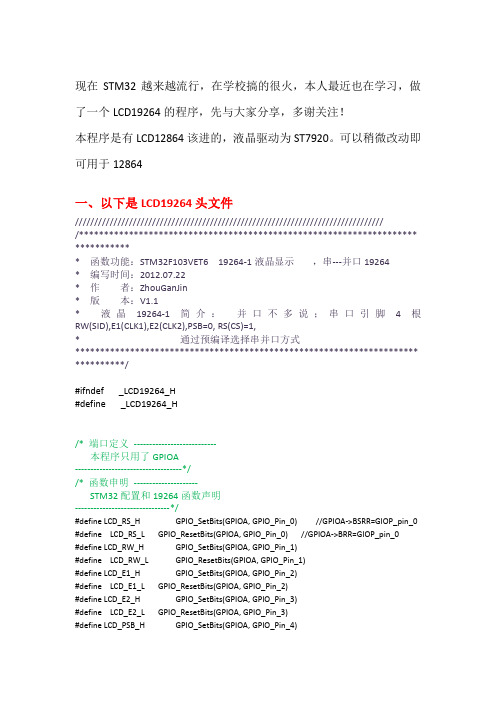
现在STM32越来越流行,在学校搞的很火,本人最近也在学习,做了一个LCD19264的程序,先与大家分享,多谢关注!本程序是有LCD12864该进的,液晶驱动为ST7920。
可以稍微改动即可用于12864一、以下是LCD19264头文件/////////////////////////////////////////////////////////////////////////////////******************************************************************** ************ 函数功能:STM32F103VET6 19264-1液晶显示,串---并口19264* 编写时间:2012.07.22* 作者:ZhouGanJin* 版本:V1.1* 液晶19264-1简介:并口不多说;串口引脚4根RW(SID),E1(CLK1),E2(CLK2),PSB=0, RS(CS)=1,* 通过预编译选择串并口方式********************************************************************* **********/#ifndef _LCD19264_H#define _LCD19264_H/* 端口定义---------------------------本程序只用了GPIOA-----------------------------------*//* 函数申明---------------------STM32配置和19264函数声明-------------------------------*/#define LCD_RS_H GPIO_SetBits(GPIOA, GPIO_Pin_0) //GPIOA->BSRR=GIOP_pin_0 #define LCD_RS_L GPIO_ResetBits(GPIOA, GPIO_Pin_0) //GPIOA->BRR=GIOP_pin_0#define LCD_RW_H GPIO_SetBits(GPIOA, GPIO_Pin_1)#define LCD_RW_L GPIO_ResetBits(GPIOA, GPIO_Pin_1)#define LCD_E1_H GPIO_SetBits(GPIOA, GPIO_Pin_2)#define LCD_E1_L GPIO_ResetBits(GPIOA, GPIO_Pin_2)#define LCD_E2_H GPIO_SetBits(GPIOA, GPIO_Pin_3)#define LCD_E2_L GPIO_ResetBits(GPIOA, GPIO_Pin_3)#define LCD_PSB_H GPIO_SetBits(GPIOA, GPIO_Pin_4)#define LCD_PSB_L GPIO_ResetBits(GPIOA, GPIO_Pin_4)#define LCD_DATA_PORT GPIOD#define LCD_DATA GPIOD->BSRR //BSRR高十六位是复位,低十六位是置位void Lcm_Wr_Dat(u8 wrdata,u8 enable); //写数据void Lcm_Wr_Com(u8 wrcommand,u8 enable); //写指令void Lcm_Rd_Status(u8 enable);//读忙状态void Lcm_Init(u8 enable); //液晶初始化void Lcm_GotoXY(u8 pos_X,u8 pos_y); //设定坐标void Lcm_SETXY(u8 pos_X,u8 pos_y,u8 enable);void Lcm_Disp_Char(u8 onechar,u8 enable);//显示单个字符void Lcm_Disp_Char_setxy(u8 x,u8 y,u8 ch,u8 enable); //定坐标显示单个字符void Lcm_Disp_Str(u8 *string,u8 enable);//显示字符串void Lcm_Disp_Str_setxy(u8 x,u8 y,u8 *strings,u8 enable);//定坐标显示字符串void Delay_ms(u32 m);//1ms延时void Lcm_Delay(void);/*function all ------函数定义-------------以下函数包含19264液晶的串并行方式----------------------------------------*/#define PSB_SERIAL 0#ifdef PSB_SERIAL// -------以下为串口函数-------- serial transmission------/////-----------传送8bits 数据----void Send_byte(u8 bbyte,u8 enable){u8 i;for(i=0;i<8;i++){LCD_E1_L; LCD_E2_L;if(0x80&bbyte) LCD_RW_H; //SID=1;else LCD_RW_L;if(!enable) //CLK = 01 ; 串行用下降沿{LCD_E1_H;Lcm_Delay();LCD_E1_L;}else{LCD_E2_H;Lcm_Delay();LCD_E2_L;}bbyte<<=1;Lcm_Delay(); //?}}//-----------写指令函数----void Lcm_Wr_Com(u8 wcomd,u8 enable){Lcm_Delay();Send_byte(0xf8,enable); //1111_1,RW(0),RS(0),0 -----------指令Send_byte(0xf0&wcomd,enable); //high 4bitsSend_byte(0xf8&(wcomd<<4),enable); //low 4bits}//-----------写数据函数----void Lcm_Wr_Dat(u8 wdata,u8 enable){Lcm_Delay();Send_byte(0xfa,enable); //1111_1,RW(0),RS(1),0 ---------数据Send_byte(0xf0&wdata,enable); //high 4bitsSend_byte(0xf8&(wdata<<4),enable); //low 4bits}#else// -------以下为并口函数-------- parallel Transmission-------/// //---------读忙函数----------------void Lcm_Rd_Status(u8 enable){u16 getd;while(1){Lcm_Delay();LCD_RS_L; //命令LCD_RW_H; //读取Lcm_Delay();//LCD_DATA=0xFFFF0000; //LCD_DATA=0xFF; 高16位为复位,即写入0使其不忙GPIO_Write(LCD_DATA_PORT, 0XFFFF) ; //准备读取数据, 写0x0000则与上相同Lcm_Delay();if(!enable){LCD_E1_L;Lcm_Delay();LCD_E1_H;getd=GPIO_ReadInputData(LCD_DATA_PORT);if((getd&0x0080)==0)break;}else{LCD_E2_L;Lcm_Delay();LCD_E2_H;if((getd&0x0080)==0)break;}}}//-----写指令----------------void Lcm_Wr_Com(u8 wcomd,u8 enable){Lcm_Rd_Status(enable);Lcm_Delay();LCD_RS_L;Lcm_Delay();LCD_RW_L;Lcm_Delay();LCD_DATA=wcomd|(~wcomd<<16); //Lcm_Delay();if(!enable){LCD_E1_H;Lcm_Delay();LCD_E1_L;}else{LCD_E2_H;Lcm_Delay();LCD_E2_L;}// Lcm_Delay();}//------写数据----------------void Lcm_Wr_Dat(u8 wdata,u8 enable) {Lcm_Rd_Status(enable);Lcm_Delay();LCD_RS_H;Lcm_Delay();LCD_RW_L;Lcm_Delay();LCD_DATA=wdata|(~wdata<<16);Lcm_Delay();if(!enable){LCD_E1_H;Lcm_Delay();LCD_E1_L;}else{LCD_E2_H;Lcm_Delay();LCD_E2_L;}}#endif//----选定坐标,全屏选择---------- void Lcm_GotoXY(u8 pos_x,u8 pos_y) {u8 addr;if((pos_x>11)||(pos_y>1))return;if(pos_y==0)addr=0x80+pos_x;else if(pos_y==1)addr=0x90+pos_x;Lcm_Wr_Com(addr,0);//设定DDRAM地址Lcm_Wr_Com(addr,1);//设定DDRAM地址}//---选定坐标,分屏选择------------void Lcm_SETXY(u8 pos_x,u8 pos_y,u8 enable){u8 addr;if((pos_x>11)||(pos_y>1))return;if(pos_y==0)addr=0x80+pos_x;else if(pos_y==1)addr=0x90+pos_x;if(enable==0)Lcm_Wr_Com(addr,0);//设定DDRAM地址elseLcm_Wr_Com(addr,1);//设定DDRAM地址}//----------初始化----------------void Lcm_Init(u8 enable){#ifdef PSB_SERIALLCD_PSB_L; //选择串口#elseLCD_PSB_H; //选择并口#endifLcm_Wr_Com(0x30,enable);Delay_ms(2);Lcm_Wr_Com(0x30,enable);Delay_ms(2);Lcm_Wr_Com(0x0c,enable); //开显示及光标设置Delay_ms(2);Lcm_Wr_Com(0x01,enable); //显示清屏Delay_ms(3);Lcm_Wr_Com(0x06,enable); //显示光标移动设置Delay_ms(3);}/*--------- display function----------以下为各种显示函数---------------------------------------*/void Lcm_Disp_Char(u8 onechar,u8 enable)//显示单个字符{Lcm_Wr_Dat(onechar,enable);}void Lcm_Disp_Str(u8 *strings,u8 enable)//显示字符串{while(*strings != '\0')Lcm_Wr_Dat(*strings++,enable);Lcm_Wr_Dat('\0',enable);}void Lcm_Disp_Char_setxy(u8 x,u8 y,u8 ch,u8 enable) //指定坐标显示字符{Lcm_GotoXY(x, y);Lcm_Wr_Dat(ch,enable);}void Lcm_Disp_Str_setxy(u8 x,u8 y,u8 *strings,u8 enable)//指定坐标显示字符串{Lcm_GotoXY(x, y);while(*strings != '\0')Lcm_Wr_Dat(*strings++,enable);Lcm_Wr_Dat('\0',enable);}二、以下是STM32配置函数/* 函数申明---------------------STM32配置和19264函数声明-------------------------------*/void RCC_Configuration(void);void GPIO_Configuration(void);void NVIC_Configuration(void);void WWDG_Configuration(void);/********************************************************************** ************* 函数名称:RCC_Configuration(void)** 函数功能:时钟初始化** 输入:无** 输出:无** 返回:无********************************************************************* ************/GPIO_InitTypeDef GPIO_InitStructure;ErrorStatus HSEStartUpStatus;void RCC_Configuration(void){/* RCC system reset(for debug purpose) */RCC_DeInit();/* Enable HSE */RCC_HSEConfig(RCC_HSE_ON);/* Wait till HSE is ready */HSEStartUpStatus = RCC_WaitForHSEStartUp();if(HSEStartUpStatus == SUCCESS){/* HCLK = SYSCLK */RCC_HCLKConfig(RCC_SYSCLK_Div1);/* PCLK2 = HCLK */RCC_PCLK2Config(RCC_HCLK_Div1);/* PCLK1 = HCLK/2 */RCC_PCLK1Config(RCC_HCLK_Div2);/* Flash 2 wait state */FLASH_SetLatency(FLASH_Latency_2);/* Enable Prefetch Buffer */FLASH_PrefetchBufferCmd(FLASH_PrefetchBuffer_Enable);/* PLLCLK = 8MHz * 9 = 72 MHz */RCC_PLLConfig(RCC_PLLSource_HSE_Div1, RCC_PLLMul_9);/* Enable PLL */RCC_PLLCmd(ENABLE);/* Wait till PLL is ready */while(RCC_GetFlagStatus(RCC_FLAG_PLLRDY) == RESET){}/* Select PLL as system clock source */RCC_SYSCLKConfig(RCC_SYSCLKSource_PLLCLK);/* Wait till PLL is used as system clock source */while(RCC_GetSYSCLKSource() != 0x08){}}}/********************************************************************** ************* 函数名称:GPIO_Configuration(void)** 函数功能:端口初始化** 输入:无** 输出:无** 返回:无********************************************************************* ************/void GPIO_Configuration(void){//定义端口结构体GPIO_InitTypeDef GPIO_InitStructure;//将GPIOA端口使能有效RCC_APB2PeriphClockCmd( RCC_APB2Periph_GPIOA , ENABLE );GPIO_InitStructure.GPIO_Pin = GPIO_Pin_0 | //GPIOAGPIO_Pin_1 |GPIO_Pin_2 |GPIO_Pin_3 |GPIO_Pin_4 |GPIO_Pin_5 |GPIO_Pin_6 |GPIO_Pin_7 |GPIO_Pin_8 |GPIO_Pin_9 |GPIO_Pin_10 |GPIO_Pin_11 |GPIO_Pin_12 ;GPIO_InitStructure.GPIO_Mode = GPIO_Mode_Out_PP; // 推挽输出GPIO_InitStructure.GPIO_Speed = GPIO_Speed_50MHz; // 最高输出速率50MHz GPIO_Init(GPIOA, &GPIO_InitStructure); // 选择A端口}/********************************************************************** ************* 函数名称:NVIC_Configuration(void)** 函数功能:中断初始化** 输入:无** 输出:无** 返回:无********************************************************************* ************/void NVIC_Configuration(void){NVIC_InitTypeDef NVIC_InitStructure;NVIC_PriorityGroupConfig(NVIC_PriorityGroup_0);NVIC_InitStructure.NVIC_IRQChannel = WWDG_IRQChannel;NVIC_InitStructure.NVIC_IRQChannelPreemptionPriority = 0;NVIC_Init(&NVIC_InitStructure);}/******************************************************************************** *函数功能:延时函数/*--- Delay function-----------------延时函数定义********************************************************************* ************///------1ms延时------------void Delay_ms(u32 m){u32 i;for(; m != 0; m--)for (i=0; i<25000; i++); //clk=50MHz ,25_000000 分频得1s,25000分频得1ms}//---------液晶延时----------void Lcm_Delay(void){u8 j,i=100;while(i--){for(j=0;j<100;j++){;}}}#endif/*************结束***************/。
- 1、下载文档前请自行甄别文档内容的完整性,平台不提供额外的编辑、内容补充、找答案等附加服务。
- 2、"仅部分预览"的文档,不可在线预览部分如存在完整性等问题,可反馈申请退款(可完整预览的文档不适用该条件!)。
- 3、如文档侵犯您的权益,请联系客服反馈,我们会尽快为您处理(人工客服工作时间:9:00-18:30)。
精心整理12864串行stm32f103zet6战舰V3学习版
在资料最下面有工程文件,直接烧录就可以使用。
希望大家尊重我的劳动成果,下载下来。
每个语句注释,在工程文件中都有。
12864相关驱动在key.c和Key.h中
经我验证,可以用stm32引脚控制12864
如上图为12864串口时序图
串行数据传送共分三个字节完成:
第一字节:串口控制—格式11111ABC
A为数据传送方向控制:H表示数据从LCD到MCU,L表示数据从MCU到LCD
B为数据类型选择:H表示数据是显示数据,L表示数据是控制指令
C固定为0
第二字节:(并行)8位数据的高4位—格式DDDD0000
第三字节:(并行)8位数据的低4位—格式0000DDDD
以上是说明书给的出的,
个人理解
从图上可以看出串行传输时需要用到CS,SCLK,SID三根信号线,但是由于CS 是高电平有效,所以也可以把CS长接高电平,那样就只需要两根线就OK了,当然当使用12864串行模式时,PSB引脚必须接低电平,复位RST引脚可以悬空不接,因为12864内部有上电复位电路。
所以电路图如下图所示
一定要查资料,看下PSB引脚是否和VCC连接在一起,我在育松上买的
QC12864B,液晶屏幕,太垃圾了,资料上都没有说明串行该怎么修改,结果调试时候发现,PSB引脚电平不对,后来一查,PSB引脚和VCC连接在一起了,所以一定要确保引脚电平正确。
串行数据传送共分三个字节完成:——理解就是传输一个字节需要三个字节来确定。
第一个字节:11111ABC
11111000单片机写控制指令给LCD
11111010单片机写数据给LCD
第三个字节:00001111
由于数据是传输是以一个字节8bits为单位,所以下面贴出传输一个字节的函数实现
voidWrite_Bits(u8bits)
{
u8i,Temp_Data;
for(i=0;i<8;i++)
{
Temp_Data=bits<<i;
if((Temp_Data&0x80)==0)
{
Reset_SID;
Reset_SCLK;
Set_SCLK;
}
else
{
Set_SID;
Reset_SCLK;
Set_SCLK;
}
}
}
Temp_Data?=?W_bits<<i?;
//把数据依次左移?对于这个语句有点迷茫,知道是左移,有点疑惑,赶紧去百度,木有找到我心中的疑问,就去翻C语言书(一本好的C语言书是多重要,我用的是CPrimerPlus),第500页,有这样一句话,该操作产生一个新的位置,但是不改变其运算对象。
例如,假设stonk为1,那么stonk<<2为4,但是stonk本身不变,仍为1。
就是a=stonk<<2;(a=4,stonk=1)
在絮叨一句,传入形参数值bits不变,每次左移i位,新值付给Temp_Data,用一个if-else语句判断SID上的高低电平,然后再把数据传输出。
第一个字节:11111ABC
11111000单片机写控制指令给LCD
11111010单片机写数据给LCD
因为第一个字节不是固定的,RS和RW不一样,意义不同,故用形参。
voidLCD_Write_Byte(u8RW,u8RS,u8byta)
{
u8H_data,L_data;
u8SID_data=0xf8;//11111000
if(1==RW)
{
SID_data|=0x04;
}
else
{
SID_data&=~0x04;
}
if(1==RS)
{
SID_data|=0x02;
}
else
{
SID_data&=~0x02;
}
H_data=byta;
H_data&=0xf0;
L_data=byta;
L_data&=0x0f;
L_data<<=4;
Write_Bits(SID_data);
delay_us(250);
Write_Bits(H_data);
delay_us(250);
Write_Bits(L_data);
delay_us(250);
}
用逻辑串口查看引脚SID,CKK时序
主函数中用
LCD_Write_Byte(0,1,0X89);//写命令字
LCD_Write_Byte(0,0,0X31);//写命令字
时序图如图,
经对比,和串行时序图一直
在这里出现一个问题,地址归位放在清屏前,屏幕会会在左上角出现相同的数字,用单步仿真却正确。
如果把“地址归位”放在最后,莫名其妙问题就能处理了。
出现乱码,开始时有规律的乱码,后来是无规律的乱码,最终发现是用排线造成电压不稳,造成时序错误,固定死电源线后,正常。
选中——右键——保存文件即可。