步进电机PLC控制技术中英文对照外文翻译文献
步进电机的单片机控制外文翻译

附录2:英文资料及其中文翻译Stepper motor is an electrical pulse will be converted into angular displacement of the implem enting agencies. Put it in simple language-speaking: When the stepper drive pulse signal to a r eceiver, it drives stepper motor rotation direction by setting a fixed point of view (and the ste p angle). You can control the number of pulses to control the amount of angular displacement, so as to achieve the purpose of accurate positioning; At the same time, you can by controllin g the pulse frequency to control the motor rotation speed and acceleration, so as to achieve th e purpose of speed.Stepper motor directly from the AC-DC power supply, and must use special equipment - stepp er motor drive. Stepper motor drive system performance, in addition to their own performance with the motor on the outside, but also to a large extent depend on the drive is good or bad.A typical stepper motor drive system is operated by the stepper motor controller, stepper mot or drives and stepper motor body is composed of three parts. Stepper motor controller stepper pulse and direction signal, each made of a pulse, stepper motor-driven stepper motor drives a rotor rotating step angle, that is, step-by-step further. High or low speed stepper motor, or spe ed, or deceleration, start or stop pulses are entirely dependent on whether the level or frequenc y. Decide the direction of the signal controller stepper motor clockwise or counterclockwise rot ation. Typically, the stepper motor drive circuit from the logic control, power driver circuit, pr otection circuit and power components. Stepper motor drive controller, once received from the direction of the signal and step pulse, the control circuit on a pre-determined way of the electr ical power-phase stepper motor excitation windings of the conduction or cut-off signal. Control circuit output signal power is low, can not provide the necessary stepping motor output powe r, the need for power amplifier, which is stepper motor driven power drive part. Power stepper motor drive circuit to control the input current winding to form a space for rotating magnetic field excitation, the rotor-driven movement. Protection circuit in the event of short circuit, ove rload, overheating, such as failure to stop the rapid drive and motor.Motor is usually for the permanent magnet rotor, when the current flows through the stator wi ndings, the stator windings produce a magnetic field vector. The magnetic field will lead to a rotor angle of rotation, making a pair of rotor and stator magnetic field direction of the magne tic field direction. When the stator rotating magnetic field vector from a different angle. Also as the rotor magnetic field to a point of view. An electrical pulse for each input, the motor r otation angle step. Its output and input of the angular displacement is proportional to the pulse s, with pulse frequency proportional to speed. Power to change the order of winding, the elect rical will be reversed. We can, therefore, control the pulse number, frequency and electrical po wer windings of each phase to control the order of rotation of stepper motor.Stepper motor types:Permanent magnet (PM). Magnetic generally two-phase stepper, torque and are smaller and gen erally stepping angle of 7.5 degrees or 15 degrees; put more wind for air-conditioning. Reactive (VR), the domestic general called BF, have a common three-phase reaction, step angl e of 1.5 degrees; also have five-phase reaction. Noise, no torque has been set at a large numb er of out.Hybrid (HB), common two-phase hybrid, five-phase hybrid, three-phase hybrid, four-phase hybri d, two-phase can be common with the four-phase drive, five-phase three-phase must be used w ith their drives;Two-phase, four-phase hybrid step angle is 1.8 degrees more than a small size, great distance, and low noise;Five-phase hybrid stepping motor is generally 0.72, the motor step angle small, high resolution, but the complexity of drive circuits, wiring problems, such as the 5-phase system of 10 lines. Three-phase hybrid stepping motor step angle of 1.2 degrees, but according to the use of 1.8 degrees, the three-phase hybrid stepping motor has a two-phase mixed than the five-phase hybr id more pole will help electric folder symmetric angle, it can be more than two-phase, five-ph ase high accuracy, the error even smaller, run more smoothly.Stepper motor to maintain torque: stepper motor power means no rotation, the stator locked rot or torque. It is a stepper motor, one of the most important parameters, usually in the low-spee d stepper motor torque at the time of close to maintain the torque. As the stepper motor outp ut torque increases with the speed of constant attenuation, the output power also increases with the speed of change, so as to maintain torque on the stepper motor to measure the parameter s of one of the most important. For example, when people say that the stepper motor 2N.m, i n the absence of special circumstances that means for maintaining the torque of the stepper m otor 2N.m.Precision stepper motors: stepper motor step angle accuracy of 3-5%, not cumulative.Start frequency of no-load: the stepper motor in case of no-load to the normal start of the pul se frequency, if the pulse frequency is higher than the value of motor does not start, possible to lose steps or blocking. In the case of the load, start frequency should be lower. If you wa nt to achieve high-speed rotation motor, pulse frequency should be to accelerate the process, th at is, the lower frequency to start, and then rose to a certain acceleration of the desired freque ncy (motor speed from low rise to high-speed).Step angle: that is to send a pulse, the electrical angle corresponding to rotation.Torque positioning: positioning torque stepper motor does not refer to the case of electricity, l ocked rotor torque stator.Operating frequency: step-by-step stepper motor can run without losing the highest frequency. Subdivision Drive: stepper motor drives the main aim is to weaken or eliminate low-frequency vibration of the stepper motor to improve the accuracy of the motor running. Reduce noise. I f the step angle is 1.8 °(full step) the two-phase hybrid stepping motor, if the breakdown of the breakdown of the number of drives for the 8, then the operation of the electrical pulse for each resolution of 0.072 °, the precision of motor can reach or close to 0.225 °, also depend s on the breakdown of the breakdown of the drive current control accuracy and other factors, the breakdown of the number of the more difficult the greater the precision of control.步进电机是一种将电脉冲转化为角位移的执行机构。
PLC及变频器技术论文中英文资料对照外文翻译文献综述

PLC及变频器技术中英文资料对照外文翻译文献综述PLC and inverter technology trends1. The development trend of the programmable controller“PLC is one kind specially for the digital operation operation electronic installation which applies under the industry environment designs. It uses may the coding memory, uses for in its internal memory operation and so on actuating logic operation, sequence operation, time, counting and arithmetic operation instructions, and can through digital or the simulation-like input and the output, controls each type the machinery or the production process. PLC and the related auxiliary equipment should according to form a whole easy with the industrial control system, easy to expand its function the principle to design.”In the 21st century, PLC will have a bigger development. Technologically speaking, computer technology's new achievement more will apply in the programmable controller's design and the manufacture, will have the operating speed to be quicker, the storage capacity to be bigger, an intelligent stronger variety to appear; Looked from the product scale that further develops to subminiature and the ultra-large direction; Looked from the product overcoatability that the product variety will be richer, the specification to be more complete, the perfect man-machine contact surface, the complete communication facility will adapt each industrial control situation demand well; Looked from the market that various countries will produce the multi-variety product the situation to break respectively along with the international competition aggravating, will present the minority several brand monopoly international market the aspect, will present the international general programming language; Looking from the network state of play, the programmable controller and other industrial control computer networkconstitution large-scale control system is the programmable controller technology development direction. Present computer collection and distribution control system DCS (Distributed Control System) had the massive programmable controller application. Is following computer network's development, the programmable controller takes the automation directed net and the international universal network important component, outside industry and industry numerous domain display more and more major function.2. Inverter technology development trendsInverter into the practical phase of more than 1 / 4 century during this period, the frequency converter technology as the basis of power electronics technology and microelectronics technology manager of a leap in the development, as the new power electronic devices and high-performance microprocessor The application of control technology and the development of increasingly high cost performance of the inverter, more and more small size, but manufacturers are still in constant frequency converter to achieve the further miniaturization and doing new efforts. From a technical point of view, with the frequency converter to further expand the market of the future, with the converter and inverter technology will be on the development of technologies in the following areas further development:(1) large capacity and small size;(2) high-performance and multi-function;(3) enhance the ease-of-use;(4) increase in life expectancy and reliability;(5) of pollution-free.Large capacity and small size of the power semiconductor devices will be with the development of continuous development. In recent years, driven by a voltage power semiconductor devices IGBT (Isolated Gate Bipolar Transistor, isolation gate bipolar transistors) has developed very rapidly and quickly into the traditional use of BJT (bipolar power transistor) and power MOSFET (FET) The various fields. In addition, the IGBT switching device for the IPM (Intelligent Power Module, IPM) and Monolithic Power IC chip will power switching devices and driving circuit, such as the protection of integrated circuits in the same package, with high performance andreliability The merits, with their high current and high pressure of the development of small and medium-sized converter will certainly be more widely used.With micro-electronics technology and semiconductor technology development, for Inverter CPU and semiconductor devices and a variety of sensors of getting higher and higher. With the frequency converter technology and the development of the growing maturity of the exchange governor, modern control theory are constantly new applications. These have further improved the performance of inverter provided the conditions. In addition, with the frequency converter to further promote the use and support are also constantly made new demands, the frequency converter manufacturers to continuously improve the performance and frequency converter functions in Inverter new efforts to meet user And the need for the fierce competition in the market in an invincible position.With the frequency converter market continues to expand, how to further enhance the ease-of-use inverter, so that the technical staff and even ordinary non-technical staff can quickly master the use of frequency converter technology has become manufacturers must consider the issue. Because only easy-to-use products can continue to acquire new customers and further expand the market, so the future of the new converter will be more easy to operate.With the development of semiconductor technology and the development of power electronics technology, the frequency converter used in the various components of the life and reliability are constantly improving, they will make their own life and the frequency converter to further increase reliability.In recent years, people have attached great importance to environmental issues, and thus a "green products" name. Therefore, the inverter, must also consider its impact on the surrounding environment.Promote the use of the frequency converter in the early stages of the noise problem was once a big problem. With the low-noise converter IGBT the emergence of this issue has basically been resolved. However, with the noise problem to solve, people's looks and a converter to the surrounding environment and the impact of other continuously explore new solutions. For example, the use of a diode-voltage converter and PWMinverter circuit converter, the frequency converter itself the high harmonics will bring supply voltage and current distortion, and at the same power to affect the other equipment. However, through the use of the frequency converter Rectifier circuit PWM, we can basically solve the problem. Although because of price and control technology and other aspects of the reasons for the current PWM converter has not been promoting the inverter, but, with the frequency converter technology development and the people of the importance of environmental issues.PLC及变频器技术的发展趋势1.可编程控制器的发展趋势可编程控制器是一种数字运算操作的电子系统,专为在工业环境下应用而设计。
(完整版)PLC英文文献+翻译

自动化专业本科毕业设计英文翻译学院(部):专业班级:学生姓名:指导教师:年月日Programmable Logic ControllerONE:PLC overviewProgrammable controller is the first in the late 1960s in the United States, then called PLC programmable logic controller (Programmable Logic Controller) is used to replace relays. For the implementation of the logical judgment, timing, sequence number, and other control functions. The concept is presented PLC General Motors Corporation. PLC and the basic design is the computer functional improvements, flexible, generic and other advantages and relay control system simple and easy to operate, such as the advantages of cheap prices combined controller hardware is standard and overall. According to the practical application of target software in order to control the content of the user procedures memory controller, the controller and connecting the accused convenient target.In the mid-1970s, the PLC has been widely used as a central processing unit microprocessor, import export module and the external circuits are used, large-scale integrated circuits even when the Plc is no longer the only logical (IC) judgment functions also have data processing, PID conditioning and data communications functions. International Electro technical Commission (IEC) standards promulgated programmable controller for programmable controller draft made the following definition : programmable controller is a digital electronic computers operating system, specifically for applications in the industrial design environment. It used programmable memory, used to implement logic in their internal storage operations, sequence control, timing, counting and arithmetic operations, such as operating instructions, and through digital and analog input and output, the control of various types of machinery or production processes. Programmable controller and related peripherals, and industrial control systems easily linked to form a whole, to expand its functional design. Programmable controller for the user, is a non-contact equipment, the procedures can be changed to change production processes. The programmable controller has become a powerful tool for factory automation, widely popular replication.Programmable controller is user-oriented industries dedicated control computer, with many distinctive features.First, high reliability, anti-interference capability;Second,programming visual, simple;Third, adaptability good;Fourth functional improvements, strong functional interface. TWO:History of PLCProgrammable Logic Controllers (PLC), a computing device invented by Richard E. Morley in 1968, have been widely used in industry including manufacturing systems, transportation systems, chemical process facilities, and many others. At that time, the PLC replaced the hardwired logic with soft-wired logic or so-called relay ladder logic (RLL), a programming language visually resembling the hardwired logic, and reduced thereby the configuration time from 6 months down to 6 days [Moody and Morley, 1999].Although PC based control has started to come into place, PLC based control will remain the technique to which the majority of industrial applications will adhere due to its higher performance, lower price, and superior reliability in harsh environments. Moreover, according to a study on the PLC market of Frost and Sullivan [1995], an increase of the annual sales volume to 15 million PLC per year with the hardware value of more than 8 billion US dollars has been predicted, though the prices of computing hardware is steadily dropping. The inventor of the PLC, Richard E Morley, fairly considers the PLC market as a 5-billion industry at the present time.Though PLCs are widely used in industrial practice, the programming of PLC based control systems is still very much relying on trial-and-error. Alike software engineering, PLC software design is facing the software dilemma or crisis in a similar way. Morley himself emphasized this aspect most forcefully by indicatingIf houses were built like software projects, a single woodpecker could d estroy civilization.”Particularly, practical problems in PLC programming are to eliminate software bugs and to reduce the maintenance costs of old ladderlogic programs. Though the hardware costs of PLC are dropping continuously, reducing the scan time of the ladder logic is still an issue in industry so that low-cost PLC can be used.In general, the productivity in generating PLC is far behind compared to other domains, for instance, VLSI design, where efficient computer aided design tools are in practice. Existent software engineering methodologies are not necessarily applicable to the PLC based software design because PLC-programming requires a simultaneous consideration of hardware and software. The software design becomes, thereby, more and more the major cost driver. In many industrial design projects, more than of the manpower allocated for the control system design and installation is scheduled for testing and debugging PLC programs.In addition, current PLC based control systems are not properly designed to support the growing demand for flexibility and reconfigurability of manufacturing systems. A further problem, impelling the need for a systematic design methodology, is the increasing software complexity in large-scale projects.The objective of this thesis is to develop a systematic software design methodology for PLC operated automation systems. The design methodology involves high-level description based on state transition models that treat automation control systems as discrete event systems, a stepwise design process, and set of design rules providing guidance and measurements to achieve a successful design. The tangible outcome of this research is to find a way to reduce the uncertainty in managing the control software development process, that is, reducing programming and debugging time and their variation, increasing flexibility of the automation systems, and enabling software reusability through modularity. The goal is to overcome shortcomings of current programming strategies that are based on the experience of the individual software developer. Three:now of PLCFrom the structure is divided into fixed PLC and Module PLC, the two kinds of PLC including CPU board, I/O board, display panel, memory block, power, these elements into a do not remove overall. Module type PLC including CPU module, I/O modules, memory, thepower modules, bottom or a frame, these modules can be according to certain rules combination configuration.In the user view, a detailed analysis of the CPU's internal unnecessary, but working mechanism of every part of the circuit. The CPU control works, by it reads CPU instruction, interprets the instruction and executes instructions. But the pace of work by shock signal control.Unit work under the controller command used in a digital or logic operations.In computing and storage register of computation result, it is also among the controller command and work. CPU speed and memory capacity is the important parameters fot PLC . its determines the PLC speed of work, IO PLC number and software capacity, so limits to control size.Central Processing Unit (CPU) is the brain of a PLC controller. CPU itself is usually one of the microcontrollers. Aforetime these were 8-bit microcontrollers such as 8051, and now these are 16-and 32-bit microcontrollers. Unspoken rule is that you’ll find mostly Hitachi and Fujicu microcontrollers in PLC controllers by Japanese makers, Siemens in European controllers, and Motorola microcontrollers in American ones. CPU also takes care of communication, interconnectedness among other parts of PLC controllers, program execution, memory operation, overseeing input and setting up of an output.System memory (today mostly implemented in FLASH technology) is used by a PLC for a process control system. Aside form. this operating system it also contains a user program translated foram ladder diagram to a binary form. FLASH memory contents can be changed only in case where user program is being changed. PLC controllers were used earlier instead of PLASH memory and have had EPROM memory instead of FLASH memory which had to be erased with UV lamp and programmed on programmers. With the use of FLASH technology this process was greatly shortened. Reprogramming a program memory is done through a serial cable in a program for application development.User memory is divided into blocks having special functions. Some parts of a memory are used for storing input and output status. The real status of an input is stored either as “1”or as “0”in a specific memory bit/each input or output has one corresponding bit in memory. Other parts of memory are used to store variable contents for variables used in used program. For example, time value, or counter value would be stored in this part of the memory.PLC controller can be reprogrammed through a computer (usual way), but also through manual programmers (consoles). This practically means that each PLC controller can programmed through a computer if you have the software needed for programming. Today’s transmission computers are ideal for reprogramming a PLC controller in factory itself. This is of great importance to industry. Once the system is corrected, it is also important to read the right program into a PLC again. It is also good to check from time to time whether program in a PLC has not changed. This helps to avoid hazardous situations in factory rooms (some automakers have established communication networks which regularly check programs in PLC controllers to ensure execution only of good programs).Almost every program for programming a PLC controller possesses various useful options such as: forced switching on and off of the system input/outputs (I/O lines), program follow up in real time as well as documenting a diagram. This documenting is necessary to understand and define failures and malfunctions. Programmer can add remarks, names of input or output devices, and comments that can be useful when finding errors, or with system maintenance. Adding comments and remarks enables any technician (and not just a person who developed the system) to understand a ladder diagram right away. Comments and remarks can even quote precisely part numbers if replacements would be needed. This would speed up a repair of any problems that come up due to bad parts. The old way was such that a person who developed a system had protection on the program, so nobody aside from this person could understand how it was done. Correctly documented ladder diagram allows any technician to understand thoroughly how system functions.Electrical supply is used in bringing electrical energy to central processing unit. Most PLC controllers work either at 24 VDC or 220V AC. On some PLC controllers you’ll find electrical supply as a separatemodule. Those are usually bigger PLC controllers, while small and medium series already contain the supply module. User has to determine how much current to take from I/O module to ensure that electrical supply provides appropriate amount of current. Different types of modules use different amounts of electrical current.This electrical supply is usually not used to start external input or output. User has to provide separate supplies in starting PLC controller inputs because then you can ensure so called “pure” supply for the PLC controller. With pure supply we mean supply where industrial environment can not affect it damagingly. Some of the smaller PLC controllers supply their inputs with voltage from a small supply source already incorporated into a PLC.Four:PLC design criteriaA systematic approach to designing PLC software can overcome deficiencies in the traditional way of programming manufacturing control systems, and can have wide ramifications in several industrial applications. Automation control systems are modeled by formal languages or, equivalently, by state machines. Formal representations provide a high-level description of the behavior of the system to be controlled. State machines can be analytically evaluated as to whether or not they meet the desired goals. Secondly, a state machine description provides a structured representation to convey the logical requirements and constraints such as detailed safety rules. Thirdly, well-defined control systems design outcomes are conducive to automatic code generation- An ability to produce control software executable on commercial distinct logic controllers can reduce programming lead-time and labor cost. In particular, the thesis is relevant with respect to the following aspects.In modern manufacturing, systems are characterized by product and process innovation, become customer-driven and thus have to respond quickly to changing system requirements. A major challenge is therefore to provide enabling technologies that can economically reconfigure automation control systems in response to changing needs and new opportunities. Design and operational knowledge can be reused inreal-time, therefore, giving a significant competitive edge in industrial practice.Studies have shown that programming methodologies in automation systems have not been able to match rapid increase in use of computing resources. For instance, the programming of PLC still relies on a conventional programming style with ladder logic diagrams. As a result, the delays and resources in programming are a major stumbling stone for the progress of manufacturing industry. Testing and debugging may consume over 50% of the manpower allocated for the PLC program design. Standards [IEC 60848, 1999; IEC-61131-3, 1993; IEC 61499, 1998; ISO 15745-1, 1999] have been formed to fix and disseminate state-of-the-art design methods, but they normally cannot participate in advancing the knowledge of efficient program and system design.A systematic approach will increase the level of design automation through reusing existing software components, and will provide methods to make large-scale system design manageable. Likewise, it will improve software quality and reliability and will be relevant to systems high security standards, especially those having hazardous impact on the environment such as airport control, and public railroads.The software industry is regarded as a performance destructor and complexity generator. Steadily shrinking hardware prices spoils the need for software performance in terms of code optimization and efficiency. The result is that massive and less efficient software code on one hand outpaces the gains in hardware performance on the other hand. Secondly, software proliferates into complexity of unmanageable dimensions; software redesign and maintenance-essential in modern automation systems-becomes nearly impossible. Particularly, PLC programs have evolved from a couple lines of code 25 years ago to thousands of lines of code with a similar number of 1/O points. Increased safety, for instance new policies on fire protection, and the flexibility of modern automation systems add complexity to the program design process. Consequently, the life-cycle cost of software is a permanently growing fraction of the total cost. 80-90% of these costs are going into software maintenance, debugging, adaptation and expansion to meet changing needs.Today, the primary focus of most design research is based on mechanical or electrical products. One of the by-products of this proposed research is to enhance our fundamental understanding of design theory and methodology by extending it to the field of engineering systems design. A system design theory for large-scale and complex system is not yet fully developed. Particularly, the question of how to simplify a complicated or complex design task has not been tackled in a scientific way. Furthermore, building a bridge between design theory and the latest epistemological outcomes of formal representations in computer sciences and operations research, such as discrete event system modeling, can advance future development in engineering design.From a logical perspective, PLC software design is similar to the hardware design of integrated circuits. Modern VLSI designs are extremely complex with several million parts and a product development time of 3 years [Whitney, 1996]. The design process is normally separated into a component design and a system design stage. At component design stage, single functions are designed and verified. At system design stage, components are aggregated and the whole system behavior and functionality is tested through simulation. In general, a complete verification is impossible. Hence, a systematic approach as exemplified for the PLC program design may impact the logical hardware design.可编程控制器一、PLC概述可编程控制器是60年代末在美国首先出现的,当时叫可编程逻辑控制器PLC(Programmable Logic Controller),目的是用来取代继电器。
最新步进电机概述翻译文献综述
步进电机概述中英文资料对照外文翻译文献综述外文文献:Knowledge of the stepper motorWhat is a stepper motor:The stepping motor as executing components, electromechanical integration is one of the key products, widely used in a variety of automatic control systems. With the development of microelectronics and computer technology, the stepper motor demand grow with each passing day, has been applied in various fields of the national economy.Stepping motor is a kind of electrical pulses into angular displacement of the implementing agencies. When stepping drive receives a pulse signal, it drives stepper motor rotate in the direction set by a fixed angle ( called the " step " ), it is the rotation at a fixed angle step by step operation. The number of pulses to control the amount of angular displacement through the control, so as to achieve the purpose of accurate positioning; also can control the pulse frequency to control motor rotation speed and acceleration, so as to achieve the purpose of speed. Special motor stepper motor control can be used as a, using its no accumulation of error ( accuracy of 100% ) characteristics, widely used in all kinds of open-loop control.Now more commonly used step motor comprises stepper motor ( VR ), permanent magnet stepper motor ( PM ), hybrid stepping motor ( HB ) and single-phase stepping motor.Permanent magnet stepper motor for general two-phase, torque and small volume, the step angle is 7.5 degree or 15 degree;Reaction stepping motor is generally three-phase, can achieve a high torque output, step angle is 1.5 degrees, but the noise and vibration are great. The rotor magnetic circuit made of soft magnetic material reaction stepper motor, a multi-phase excitation winding stator, using magnetic torque changes.Hybrid stepping motor is mixed the advantages of permanent magnet type and reaction type. It is divided into two phase and five phase: two-phase stepper angle is 1.8 degree and five phase stepper angle is 0.72 degrees. Application of the stepping motor is the most widely, is also this subdivision driving of stepper motor selection scheme.Some of the basic parameters of step motor:The natural step motor:It says every hair a step pulse signal control system, motor rotation angle. Motor factory is a step angle values, such as type 86BYG250A motor is given a value of 0.9° /1.8 °( said a half step of work is 0.9 °, the whole step of work is 1.8 °), this step can be called ' motor fixed step ', it doesn't have to be the actual motor work when the real step angle, angle and drive the real steps.Stepper motor phase number:Is the number of coils inside the motor, commonly used in a two-phase, three-phase, four phase, five phase stepper motor. The number of motor phase is different, the step angle is also different, the general two-phase motor step angle is 0.9° /1.8 °, three-phase 0.75 ° /1.5 °, five phase of 0.36 ° /0.72 °. In the absence of subdivision drive, users mainly rely on different phases of the stepper motor to meet their own requirements of step angle. If you use a subdivision driver, is ' phase ' will become meaningless, users only need to change the fine fraction in the drive, you can change the step angle.Keep the torque ( HOLDINGTORQUE ):Is the stepper motor power but there is no rotation, the stator locked rotor torque. It is one of the most important parameters of step motor, usually steppermotor in the low-speed torque to keep the torque. Because of the larger output torque stepper motor with speed and continuous decay, increases the output power with the speed of change, so keep the torque becomes one of the most important parameters of step motor. For example, when people say 2N.m stepper motor, in the absence of exceptional circumstances described in that refers to keep the torque motor for the 2N.m step.DETENTTORQUE:DETENTTORQUE:Refers to the stepper motor is not energized condition, the stator locked rotor torque. DETENTTORQUE does not have a unified way of translation in China, easy to make people misunderstand; as the rotor reaction stepper motor is not permanent magnetic material, so it has no DETENTTORQUE.Some of the characteristic of step motor:The 1 stepper motor step angle accuracy for 3-5%, and no accumulation.2 stepper motor appearance allows the maximum temperature.Stepper motor temperature is too high will first make the motor magnetic material demagnetization, resulting in lower torque and loss, so the highest temperature of motor appearance allows should depend on the different motor demagnetization magnetic materials; generally speaking, demagnetization point magnetic material in 130 degrees Celsius above, some even as high as 200 degrees Celsius stepping motor, so the surface temperature at 80-90 degrees Celsius completely normal.3 stepper motor torque will decrease with the increase of rotational speed.When the stepper motor rotates, the electrical inductance of the winding will form a reverse electromotive force; the higher the frequency, the greater the reverse emf. Under the influence of it, the motor with frequency ( or speed ) increase and the phase current is reduced, resulting in lower torque.4 stepper motor speed can be normal operation, but if it is more than a certain speed will not start, and accompanied by howling.Stepper motor is a technical parameter: no-load start frequency, namely the stepper motor under no-load condition can pulse frequency start, if the pulse frequency is higher than the value, the motor can not start properly, may have lost step or stall. In under the condition of the load, start frequency should be less. If you want to enable the motor to rotate at high speed, pulse frequency should accelerate the process is started, the lower frequency, and then according to certain acceleration up to high frequency desired ( motor speed from low speed to high speed ).Characteristics of stepper motor with its significant, play an important purpose in the era of digital manufacturing. With the different development of digital technology and stepper motor itself technology improves, the stepper motor will be applied in more fields.How to determine the stepper motor driver DC power supply:A. Determination of the voltageHybrid stepping motor driver power supply voltage is generally a wide range (such as the IM483 supply voltage of 12 ~ 48VDC), the supply voltage is usually based on the work of the motor speed and response to the request to choose. If the motor operating speed higher or faster response to the request, then the voltage value is high, but note that the ripple voltage can not exceed the maximum input voltage of the drive, or it may damage the drive.B. Determination of CurrentPower supply current is generally based on the output phase current drive I to determine. If a linear power supply, power supply current is generally preferable 1.1 to 1.3 times the I; if we adopt the switching power supply, power supply current is generally preferable to I, 1.5 to 2.0 times.The main characteristics of stepping motor:A stepper motor drive can be added operate pulse drive signal must be no pulse when the stepper motor at rest, such asIf adding the appropriate pulse signal, it will to a certain angle (called the step angle) rotation. Rotation speed and pulse frequency is proportional to.2 Dragon step angle stepper motor version is 7.5 degrees, 360 degrees around, takes 48 pulses to complete.3 stepper motor has instant start and rapid cessation of superior characteristics.Change the pulse of the order of 4, you can easily change the direction of rotation. Therefore, the current printers, plotters, robotics, and so devices are the core of the stepper motor as the driving force.Stepper motor control exampleWe use four-phase unipolar stepper motor as an example. The structure shown in Figure 1:Four four-phase winding leads (as opposed to phase A1 A2 B1 phase phase B2) and two public lines (to the power of positive). The windings of one phase to the power of the ground. So that the windings will be inspired. We use four-phase eight-beat control, ie, 1 phase 2 phase alter nating turn, would enhance resolution. 0.9 ° per step can be transferred to control the motor excitation is transferred in order as follows:If the requirements of motor reversal, the transmission excitation signal can be reversed. 2 control schemeControl system block diagram is as followsThe program uses AT89S51 as the main control device. It is compatible with the AT89C51, but also increased the SPI interface and the watchdog module, which not only makes the debugging process becomes easy and also more stable. The microcontroller in the program mainly for field signal acquisition and operation of the stepper motor to calculate the direction and speed information. Then sent to the CPLD.CPLD with EPM7128SLC84-15, EPM7128 programmable logic device of large-scale, forthe ALTERA company's MAX7000 family. High impedance, electrically erasable and other characteristics, can be used for the 2500 unit, the working voltage of +5 V. CPLD receives information sent from the microcontroller after converted to the corresponding control signal output to the stepper motor drive. Put the control signal drives the motor windings after the input, to achieve effective control of the motor. 2.1 The hardware structure of the motor driveMotor drive using the following circuit:R1-R8 in which the resistance value of 320Ω. R9-R12 resistance value 2.2KΩ. Q1-Q4 as Darlington D401A, Q5-Q8 for the S8550. J1, J2 and the stepper motor connected to the six-lead。
步进电机中英文对照外文翻译文献
(文档含英文原文和中文翻译)中英文对照外文翻译附件1:外文翻译译文步进电机的振荡、不稳定以及控制摘要:本文介绍了一种分析永磁步进电机不稳定性的新颖方法。
结果表明,该种电机有两种类型的不稳定现象:中频振荡和高频不稳定性。
非线性分叉理论是用来说明局部不稳定和中频振荡运动之间的关系。
一种新型的分析介绍了被确定为高频不稳定性的同步损耗现象。
在相间分界线和吸引子的概念被用于导出数量来评估高频不稳定性。
通过使用这个数量就可以很容易地估计高频供应的稳定性。
此外,还介绍了稳定性理论。
广义的方法给出了基于反馈理论的稳定问题的分析。
结果表明,中频稳定度和高频稳定度可以提高状态反馈。
关键词:步进电机,不稳定,非线性,状态反馈。
1. 介绍步进电机是将数字脉冲输入转换为模拟角度输出的电磁增量运动装置。
其内在的步进能力允许没有反馈的精确位置控制。
也就是说,他们可以在开环模式下跟踪任何步阶位置,因此执行位置控制是不需要任何反馈的。
步进电机提供比直流电机每单位更高的峰值扭矩;此外,它们是无电刷电机,因此需要较少的维护。
所有这些特性使得步进电机在许多位置和速度控制系统的选择中非常具有吸引力,例如如在计算机硬盘驱动器和打印机,代理表,机器人中的应用等.尽管步进电机有许多突出的特性,他们仍遭受振荡或不稳定现象。
这种现象严重地限制其开环的动态性能和需要高速运作的适用领域。
这种振荡通常在步进率低于1000脉冲/秒的时候发生,并已被确认为中频不稳定或局部不稳定[1],或者动态不稳定[2]。
此外,步进电机还有另一种不稳定现象,也就是在步进率较高时,即使负荷扭矩小于其牵出扭矩,电动机也常常不同步。
该文中将这种现象确定为高频不稳定性,因为它以比在中频振荡现象中发生的频率更高的频率出现。
高频不稳定性不像中频不稳定性那样被广泛接受,而且还没有一个方法来评估它。
中频振荡已经被广泛地认识了很长一段时间,但是,一个完整的了解还没有牢固确立。
这可以归因于支配振荡现象的非线性是相当困难处理的。
plc外文文献译文
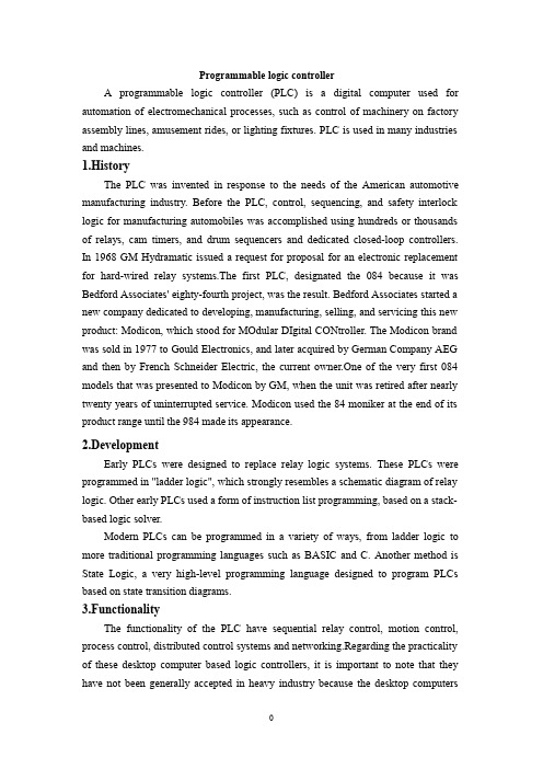
Programmable logic controllerA programmable logic controller(PLC)is a digital computer used for automation of electromechanical processes,such as control of machinery on factory assembly lines,amusement rides,or lighting fixtures.PLC is used in many industries and machines.1.HistoryThe PLC was invented in response to the needs of the American automotive manufacturing industry.Before the PLC,control,sequencing,and safety interlock logic for manufacturing automobiles was accomplished using hundreds or thousands of relays,cam timers,and drum sequencers and dedicated closed-loop controllers. In1968GM Hydramatic issued a request for proposal for an electronic replacement for hard-wired relay systems.The first PLC,designated the084because it was Bedford Associates'eighty-fourth project,was the result.Bedford Associates started a new company dedicated to developing,manufacturing,selling,and servicing this new product:Modicon,which stood for MOdular DIgital CONtroller.The Modicon brand was sold in1977to Gould Electronics,and later acquired by German Company AEG and then by French Schneider Electric,the current owner.One of the very first084 models that was presented to Modicon by GM,when the unit was retired after nearly twenty years of uninterrupted service.Modicon used the84moniker at the end of its product range until the984made its appearance.2.DevelopmentEarly PLCs were designed to replace relay logic systems.These PLCs were programmed in"ladder logic",which strongly resembles a schematic diagram of relay logic.Other early PLCs used a form of instruction list programming,based on a stack-based logic solver.Modern PLCs can be programmed in a variety of ways,from ladder logic to more traditional programming languages such as BASIC and C.Another method is State Logic,a very high-level programming language designed to program PLCs based on state transition diagrams.3.FunctionalityThe functionality of the PLC have sequential relay control,motion control, process control,distributed control systems and networking.Regarding the practicality of these desktop computer based logic controllers,it is important to note that they have not been generally accepted in heavy industry because the desktop computersrun on less stable operating systems than do PLCs,and because the desktop computer hardware is typically not designed to the same levels of tolerance to temperature, In more recent years,small products called PLRs(programmable logic relays), are used in light industry where only a few points of I/O(i.e.a few signals coming in from the real world and a few going out)are involved,and low cost is desired. Popular names include PICO Controller,NANO PLC,and other names implying very small controllers.the PLRs are usually not modular or expandable,but their price can be two orders of magnitude less than a PLC and they still offer robust design and deterministic execution of the logic.4.PLC compared with other control systemsPLCs are well-adapted to a range of automation tasks.These are typically industrial processes in manufacturing where the cost of developing and maintaining the automation system is high relative to the total cost of the automation,and where changes to the system would be expected during its operational life.PLCs contain input and output devices compatible with industrial pilot devices and controls;little electrical design is required,and the design problem centers on expressing the desired sequence of operations.PLC applications are typically highly customized systems so the cost of a packaged PLC is low compared to the cost of a specific custom-built controller design.On the other hand,in the case of mass-produced goods,customized control systems are economic due to the lower cost of the components,which can be optimally chosen instead of a"generic"solution,and where the non-recurring engineering charges are spread over thousands or millions of units.A microcontroller-based design would be appropriate where hundreds or thousands of units will be produced and so the development cost(design of power supplies,input/output hardware and necessary testing and certification)can be spread over many sales,and where the end-user would not need to alter the control. Automotive applications are an example;millions of units are built each year,and very few end-users alter the programming of these controllers.However,some specialty vehicles such as transit busses economically use PLCs instead of custom-designed controls,because the volumes are low and the development cost would be uneconomic.Programmable controllers are widely used in motion control,positioning control and torque control.Some manufacturers produce motion control units to be integrated with PLC so that G-code(involving a CNC machine)can be used to instruct machinemovements.PLCs may include logic for single-variable feedback analog control loop,a "proportional,integral,derivative"or"PID controller".A PID loop could be used to control the temperature of a manufacturing process,for example.Historically PLCs were usually configured with only a few analog control loops;where processes required hundreds or thousands of loops,a distributed control system(DCS)would instead be used.As PLCs have become more powerful,the boundary between DCS and PLC applications has become less distinct.PLCs have similar functionality as Remote Terminal Units.An RTU,however, usually does not support control algorithms or control loops.As hardware rapidly becomes more powerful and cheaper,RTUs,PLCs and DCSs are increasingly beginning to overlap in responsibilities,and many vendors sell RTUs with PLC-like features and vice versa.The industry has standardized on the IEC61131-3functional block language for creating programs to run on RTUs and PLCs,although nearly all vendors also offer proprietary alternatives and associated development environments.5.The prospects for PLC.5.1.FeaturesThe main difference from other computers is that PLCs are armored for severe conditions(such as dust,moisture,heat,cold)and have the facility for extensive input/output(I/O)arrangements.PLCs read limit switches,analog process variables (such as temperature and pressure),and the positions of complex positioning systems. Some use machine vision.On the actuator side,PLCs operate electric motors, pneumatic or hydraulic cylinders,magnetic relays,solenoids,or analog outputs.The input/output arrangements may be built into a simple PLC,or the PLC may have external I/O modules attached to a computer network that plugs into the PLC.5.2System scaleA small PLC will have a fixed number of connections built in for inputs and outputs.Typically,expansions are available if the base model has insufficient I/O. Modular PLCs have a chassis(also called a rack)into which are placed modules with different functions.The processor and selection of I/O modules is customised for the particular application.Several racks can be administered by a single processor,and may have thousands of inputs and outputs.A special high speed serial I/O link is used so that racks can be distributed away from the processor,reducing the wiring costs for large plants.5.3User interfacePLCs may need to interact with people for the purpose of configuration,alarm reporting or everyday control.A simple system may use buttons and lights to interact with the user.Text displays are available as well as graphical touch screens.More complex systems use a programming and monitoring software installed on a computer, with the PLC connected via a communication interface.5.4CommunicationsPLCs have built in communications ports,usually9-pin RS-232,but optionally EIA-485or Ethernet.Modbus,BACnet or DF1is usually included as one of the communications protocols.Other options include various fieldbuses such as DeviceNet or Profibus.Other communications protocols that may be used are listed in the List of automation protocols.Most modern PLCs can communicate over a network to some other system,such as a computer running a SCADA(Supervisory Control And Data Acquisition)system or web browser.PLCs used in larger I/O systems may have peer-to-peer(P2P)communication between processors.This allows separate parts of a complex process to have individual control while allowing the subsystems to co-ordinate over the communication link.These communication links are also often used for HMI devices such as keypads or PC-type workstations.可编程逻辑控制器可编程逻辑控制器(PLC)或可编程序控制器是用于机电过程自动化的数字计算机,例如控制机械厂生产线、游乐设施或照明的装置。
PLC中英文对照外文翻译文献
中英文对照翻译外文资料:PLC technique discussion and future developmentAlong with the development of the ages, the technique that is nowadays is also gradually perfect, the competition plays more more strong; the operation that list depends the artificial has already can't satisfied with the current manufacturing industry foreground, also can't guarantee the request of the higher quantity and high new the image of the technique business enterprise.The people see in produce practice, automate brought the tremendous convenience and the product quantities for people up of assurance, also eased the personnel's labor strength, reduce the establishment on the personnel. The target control of the hard realization in many complicated production lines, whole and excellent turn, the best decision etc., well-trained operation work, technical personnel or expert, governor but can judge and operate easily, can acquire the satisfied result. The research target of the artificial intelligence makes use of the calculator exactly to carry out, imitate these intelligences behavior, moderating the work through person's brain and calculators, with the mode that person's machine combine, for resolve the very complicated problem to look for the best pathWe come in sight of the control that links after the electric appliances in various situation, that is already the that time generation past, now of after use in the mold a perhaps simple equipments of grass-roots control that the electric appliances can do for the low level only;And the PLC emergence also became the epoch-making topic, adding the vivid software control through a very and stable hardware, making the automation head for the new high tide.The PLC biggest characteristics lie in: The electrical engineering teacher already no longer electric hardware up too many calculationses of cost, as long as order the importation that the button switch or the importation of the sensors order to link the PLC up can solve problem, pass to output to order the conjunction contact machine or control the start equipments of thebig power after the electric appliances, but the exportation equipments direct conjunction of the small power can.PLC internal containment have the CPU of the CPU, and take to have an I/ O for expand of exterior to connect a people's address and saving machine three big pieces to constitute, CPU core is from an or many is tired to add the machine to constitute, mathematics that they have the logic operation ability, and can read the procedure save the contents of the machine to drive the homologous saving machine and I/ Os to connect after pass the calculation; The I/ O add inner part is tired the input and output system of the machine and exterior link, and deposit the related data into the procedure saving machine or data saving machine; The saving machine can deposit the data that the I/ O input in the saving machine, and in work adjusting to become tired to add the machine and I/ Os to connect, saving machine separately saving machine RAM of the procedure saving machine ROM and datas, the ROM can can do deposit of the data permanence in the saving machine, but RAM only for the CPU computes the temporary calculation usage of hour of buffer space.The PLC anti- interference is very and excellent, our root need not concern its service life and the work situation bad, these all problems have already no longer become the topic that we fail, but stay to our is a concern to come to internal resources of make use of the PLC to strengthen the control ability of the equipments for us, make our equipments more gentle. PLC language is not we imagine of edit collected materials the language or language of Cs to carry on weaving the distance, but the trapezoid diagram that the adoption is original after the electric appliances to control, make the electrical engineering teacher while weaving to write the procedure very easy comprehended the PLC language, and a lot of non- electricity professional also very quickly know and go deep into to the PLC.Is PLC one of the advantage above and only, this is also one part that the people comprehend more and easily, in a lot of equipmentses, the people have already no longer hoped to see too many control buttons, they damage not only and easily and produce the artificial error easiest, small is not a main error perhaps you can still accept; But lead even is a fatal error greatly is what we can't is tolerant of. New technique always for bringing more safe and convenient operation for us, make we a lot of problems for face on sweep but light, do you understand the HMI? Says the HMI here you basically not clear what it is, also have no interest understanding, change one inside text explains it into the touch to hold or man-machine interface you knew, it combines with the PLC to our larger space.HMI the control not only only is reduced the control press button, increase the vivid of the control, more main of it is can sequence of, and at can the change data input to output thefeedback with data, control in the temperature curve of imitate but also can keep the manifestation of view to come out. And can write the function help procedure through a plait to provide the help of various what lies in one's power, the one who make operate reduces the otiose error. Currently the HMI factory is also more and more, the function is also more and more strong, the price is also more and more low, the noodles of the usage are wide more and more. The HMI foreground can say that think ° to be good very.At a lot of situations, the list is is a smooth movement that can't guarantee the equipments by the control of the single machine, but pass the information exchanges of the equipments and equipments to attain the result that we want. For example fore pack and the examination of the empress work preface, we will arrive wrapping information feedback to examine the place, and examine the information of the place to also want the feedback to packing. Pass the information share thus to make both the chain connect, becoming a total body, the match of your that thus make is more close, at each other attain to reflect the result that mutually flick. The PLC correspondence has already come more more body now its value, at the PLC and correspondence between PLCs, can pass the communication of the information and the share of the datas to guarantee that of the equipments moderates mutually, the result that arrive already to repair with each other. Data conversion the adoption RS232 between PLC connect to come to the transmission data, but the RS232 pick up a people and can guarantee 10 meters only of deliver the distance, if in the distance of 1000 meters we can pass the RS485 to carry on the correspondence, the longer distance can pass the MODEL only to carry on deliver. The PLC data transmission is just to be called a form to it in a piece of and continuous address that the data of the inner part delivers the other party, we, the PLC of the other party passes to read data in the watch to carry on the operation. If the data that data in the watch is a to establish generally, that is just the general data transmission, for example today of oil price rise, I want to deliver the price of the oil price to lose the oil ally on board, that is the share of the data; But take data in the watch for an instruction procedure that controls the PLC, that had the difficulty very much, for example you have to control one pedestal robot to press the action work that you imagine, you will draw up for it the form that a procedure combine with the data sends out to pass by.The form that information transport contain single work, the half a work and the difference of a workses .The meaning of the single work also is to say both, a can send out only, but a can receive only, for example a spy he can receive the designation of the superior only, but can't give the superior reply; A work of half is also 2 and can can send out similar to accept the data, but can't send out and accept at the same time, for example when you make a phonecall is to can't answer the phone, the other party also; But whole pair works is both can send out and accept the data, and can send out and accept at the same time. Be like the Internet is a typical example.The process that information transport also has synchronous and different step cent: The data line and the clock lines are synchronous when synchronous meaning lie in sending out the data, is also the data signal and the clock signals to be carry on by the CPU to send out at the same time, this needs to all want the specialized clock signal each other to carry on the transmission and connect to send, and is constrained, the characteristics of this kind of method lies in its speed very quick, but correspond work time of take up the CPU and also want to be long oppositely, at the same time the technique difficulty also very big. Its request lies in can'ting have an error margins in a datas deliver, otherwise the whole piece according to compare the occurrence mistake, this on the hardware is a bigger difficulty. Applied more and more extensive in some appropriative equipmentses, be like the appropriative medical treatment equipments, the numerical signal equipments...etc., in compare the one data deliver, its result is very good.And the different step is an application the most extensive, this receive benefit in it of technique difficulty is opposite and want to be small, at the same time not need to prepare the specialized clock signal, its characteristics to lie in, its data is partition, the long-lost send out and accept, be the CPU is too busy of time can grind to a stop sex to work, also reduced the difficulty on the hardware, the data throw to lose at the same time opposite want to be little, we can pass the examination of the data to observe whether the data that we send out has the mistake or not, be like strange accidentally the method, tired addition and eight efficacies method etc., can use to helps whether the data that we examine to send out have or not the mistake occurrence, pass the feedback to carry on the discriminator.A line of transmission of the information contain a string of and combine the cent of: The usual PLC is 8 machines, certainly also having 16 machines. We can be an at the time of sending out the data a send out to the other party, also can be 88 send out the data to the other party, an and 8 differentiationses are also the as that we say to send out the data and combine sends out the data. A speed is more and slowly, but as long as 2 or three lines can solve problem, and can use the telephone line to carry on the long range control. But combine the oscular transmission speed is very quick of, it is a string of oscular of 25600%, occupy the advantage in the short distance, the in view of the fact TTL electricity is even, being limited by the scope of one meter generally, it combine unwell used for the data transmission of the long pull, thus the cost is too expensive.Under a lot of circumstances we are total to like to adopt the string to combine the conversion chip to carry on deliver, under this kind of circumstance not need us to carry on to depositted the machine to establish too and complicatedly, but carry on the data exchanges through the data transmission instruction directly, but is not a very viable way in the correspondence, because the PLC of the other party must has been wait for your data exportation at the time of sending out the data, it can't do other works.When you are reading the book, you hear someone knock on door, you stop to start up of affair, open the door and combine to continue with the one who knock on door a dialogue, the telephone of this time rang, you signal hint to connect a telephone, after connecting the telephone through, return overdo come together knock on door to have a conversation, after dialogue complete, you continue again to see your book, this kind of circumstance we are called the interruption to it, it has the authority, also having sex of have the initiative, the PLC had such function .Its characteristics lie in us and may meet the urgently abrupt affairs in the operation process of the equipments, we want to stop to start immediately up of work, the whereabouts manages the more important affair, this kind of circumstance is we usually meet of, PLC while carry out urgent mission, total will keep the current appearance first, for example the address of the procedure, CPU of tired add the machine data etc., be like to to stick down which the book that we see is when we open the door the page or simply make a mark, because we treat and would still need to continue immediately after book of see the behind. The CPU always does the affair that should do according to our will, but your mistake of give it an affair, it also would be same to do, this we must notice.The interruption is not only a, sometimes existing jointly with the hour several inside break, break off to have the preferred Class, they will carry out the interruption of the higher Class according to person's request. This kind of breaks off the medium interruption to also became to break off the set. The Class that certainly break off is relevant according to various resources of CPU with internal PLC, also following a heap of capacity size of also relevant fasten.The contents that break off has a lot of kinds, for example the exterior break off, correspondence in of send out and accept the interruption and settle and the clock that count break off, still have the WDT to reset the interruption etc., they enriched the CPU to respond to the category while handle various business. Speak thus perhaps you can't comprehend the internal structure and operation orders of the interruption completely also, we do a very small example to explain.Each equipments always will not forget a button, it also is at we meet the urgent circumstance use of, that is nasty to stop the button. When we meet the Human body trouble and surprised circumstances we as long as press it, the machine stops all operations immediately, and wait for processing the over surprised empress recover the operation again.Nasty stop the internal I/ O of the internal CPU of the button conjunction PLC to connect up, be to press button an exterior to trigger signal for CPU, the CPU carries on to the I/ O to examine again, being to confirm to have the exterior to trigger the signal, CPU protection the spot breaks off procedure counts the machine turn the homologous exterior I/ O automatically in the procedure to go to also, be exterior interruption procedure processing complete, the procedure counts the machine to return the main procedure to continue to work.Have 1:00 can what to explain is we generally would nasty stop the button of exterior break off to rise to the tallest Class, thus guarantee the safety.When we are work a work piece, giving the PLC a signal, counting PLC inner part the machine add 1 to compute us for a day of workload, a count the machine and can solve problem in brief, certainly they also can keep the data under the condition of dropping the electricity, urging the data not to throw to lose, this is also what we hope earnestly.The PLC still has the function that the high class counts the machine, being us while accept some datas of high speed, the high speed that here say is the data of the in all aspects tiny second class, for example the bar code scanner is scanning the data continuously, calculating high-speed signal of the data processor DSP etc., we will adopt the high class to count the machine to help we carry on count. It at the PLC carries out the procedure once discover that the high class counts the machine to should of interruption, will let go of the work on the hand immediately. The trapezoid diagram procedure that passes by to weave the distance again explains the high class for us to carry out procedure to count machine would automatic performance to should of work, thus rise the Class that the high class counts the machine to high one Class.You heard too many this phrases perhaps:" crash", the meaning that is mostly is a workload of CPU to lead greatly, the internal resources shortage etc. the circumstance can't result in procedure circulate. The PLC also has the similar circumstance, there is a watchdog WDT in the inner part of PLC, we can establish time that a procedure of WDT circulate, being to appear the procedure to jump to turn the mistake in the procedure movement process or the procedure is busy, movement time of the procedure exceeds WDT constitution time, the CPU turn but the WDT reset the appearance. The procedure restarts the movement, but will not carry on the breakage to the interruption.The PLC development has already entered for network ages of correspondence from the mode of the one, and together other works control the net plank and I/ O card planks to carry on the share easily. A state software can pass all se hardwares link, more animation picture of keep the view to carries on the control, and cans pass the Internet to carry on the control in the foreign land, the blast-off that is like the absolute being boat No.5 is to adopt this kind of way to make airship go up the sky.The development of the higher layer needs our continuous effort to obtain.The PLC emergence has already affected a few persons fully, we also obtained more knowledge and precepts from the top one experience of the generation, coming to the continuous development PLC technique, push it toward higher wave tide.中文翻译:可编程控制器技术讨论与未来发展随着时代的发展,当今的技术也日趋完善、竞争愈演愈烈,单靠人工的操作已不能满足于目前的制造业前景,也无法保证更高质量的要求和高新技术企业的形象。
PLC中英文资料外文翻译
可编程控制器技术讨论与未来发展学生姓名: ******所在院系: ******所学专业: ******导师姓名: ******完成时间:******外文资料PLCtechnique discussion and future developmentWith the development of the times, today's technology is maturing, competition intensified。
rely on manual operation does not satisfy the current industry outlook, there is no guarantee of higher quality requirements and high-tech corporate image.People saw in the production practice, automation to bring great convenience and product quality assurance, but also reduce the labor intensity, reducing the staff on the establishment in many complex production process is difficult to achieve target control, the overall optimization, optimal decision-making, skilled operatives, technicians or specialists, managers can easily determine and operate it, you can get satisfactory results. artificial intelligence research is the use of computers to achieve the target, the analog These intelligent behavior, through coordination of the human brain and a computer to combine human models for solving very complex problem of finding the best way.PLC's most important feature is: electrical engineer electrical hardware no longer spend too much scheming, as long as the button switch or sensor input connected to the PLC input point will solve the problem by connecting the output point contacts or relay to control the power of the boot device, and small power output devices can be connected directly.Contained within the PLC having a central processor of the CPU, and with an external I / O port expansion I / O interface and the memory addresses of three major components, CPU core is formed by one or more accumulators, which have the logical math capabilities, and can read the contents of the program memory to drive through the calculation of the corresponding memory and I / O interface。
步进电机和伺服电机的系统控制英文翻译外文文献翻译、中英文翻译、外文翻译
Step Motor&Servo Motor Systems and ControlsMotion Architect® Software Does the Work for You... Configure ,Diagnose, Debug Compumotor’s Motion Architect is a Microsoft® Windows™-based software development tool for 6000Series products that allows you to automatically generate commented setup code, edit and execute motion control programs, and create a custom operator test panel. The heart of Motion Architect is the shell, which provides an integrated environment to access the following modules.• System Con figurator—This module prompts you to fill in all pertinent set-up information to initiate motion. Configurable to the specific 6000 Series product that is selected, the information is then used to generate actual 6000-language code that is the beginning of your program.• Program Editor—This module allows you to edit code. It also has the commands available through ―Help‖ menus. A user’s guide is provided on disk.• Terminal Emulator—This module allows you to interact directly with the 6000 product. ―Help‖ is again available with all commands and their definitions available for reference. • Test Panel—You can simulate your programs, debug programs, and check for program flow using this module.Motion Architect® has been designed for use with all 6000 Series products—for both servo and stepper technologies. The versatility of Windows and the 6000 Series language allow you to solve applications ranging from the very simple to the complex.Motion Architect comes standard with each of the 6000 Series products and is a tool that makes using these controllers even more simple—shortening the project development time considerably. A value-added feature of Motion Architect, when used with the 6000 Servo Controllers, is its tuning aide. This additional module allows you to graphically display a variety of move parameters and see how these parameters change based on tuning values.Using Motion Architect, you can open multiple windows at once. For example, both the Program Editor and Terminal Emulator windows can be opened to run the program, get information, and then make changes to the program.On-line help is available throughout Motion Architect, including interactive access to the contents of the Compumotor 6000 Series Software Reference Guide.SOLVING APPLICATIONS FROM SIMPLE TOCOMPLEXServo Control is Yours with Servo Tuner SoftwareCompumotor combines the 6000 Series servo controllers with Servo Tuner software. The Servo Tuner is an add-on module that expands and enhances the capabilities of Motion Architect®.Motion Architect and the Servo Tuner combine to provide graphical feedback ofreal-time motion information and provide an easy environment for setting tuning gains and related systemparameters as well as providing file operations to save and recall tuning sessions.Draw Your Own Motion Control Solutions with Motion Toolbox Software Motion Toolbox™ is an extensive library of LabVIEW® virtual instruments (VIs) for icon-based programming of Compumotor’s 6000 Series motion controllers.When using Motion Toolbox with LabVIEW, programming of the 6000 Series controller is accomplished by linking graphic icons, or VIs, together to form a block diagram. Motion Toolbox’s has a library of more than 150 command,status, and example VIs. All command and status VIs include LabVIEW source diagrams so you can modify them, if necessary, to suit your particular needs. Motion Toolbox als user manual to help you gut up and running quickly.comprehensiveM Software for Computer-Aided Motion Applications CompuCAM is a Windows-based programming package that imports geometry from CAD programs, plotter files, or NC programs and generates 6000 code compatible with Compumotor’s 6000 Series motion controllers. Available for purchase from Compumotor, CompuCAM is an add-on module which is invoked as a utility from the menu bar of Motion Architect.From CompuCAM, run your CAD software package. Once a drawing is created, save it as either a DXF file, HP-GL plot file or G-code NC program. This geometry is then imported into CompuCAM where the 6000 code is generated. After generating the program, you may use Motion Architect functions such as editing or downloading the code for execution.Motion Builder Software for Easy Programming of the 6000 SeriesMotion Builder revolutionizes motion control programming. This innovative software allows programmers to program in a way they are familiar with—a flowchart-style method. Motion Builder decreases the learning curve and makes motion control programming easy.Motion Builder is a Microsoft Windows-based graphical development environment which allows expert and novice programmers to easily program the 6000 Series products without learning a new programming language. Simply drag and drop visual icons that represent the motion functions you want to perform.Motion Builder is a complete application development environment. In addition to visually programming the 6000 Series products, users may configure, debug, download, and execute the motion program.SERVO VERSUS STEPPER... WHAT YOU NEED TOKNOWMotor Types and Their ApplicationsThe following section will give you some idea of the applications that are particularly appropriate for each motor type, together with certain applications that are best avoided. It should be stressed that there is a wide range of applications which can be equally well met by more than one motor type, and the choice will tend to be dictated by customer preference, previous experience or compatibility with existing equipment.A helpful tool for selecting the proper motor for your applicat ion is Compumotor’s Motor Sizing and Selection software package. Using this software, users can easily identify the appropriate motor size and type.High torque, low speedcontinuous duty applications are appropriate to the step motor. At low speeds it is very efficient in terms of torque output relative to both size and input power. Microstepping can be used to improve smoothness in lowspeed applications such as a metering pump drive for very accurate flow control.High torque, high speedcontinuous duty applications suit the servo motor, and in fact a step motor should be avoided in such applications because the high-speed losses can cause excessive motor heating.Short, rapid, repetitive movesare the natural domain of the stepper due to its high torque at low speeds, goodtorque-to-inertia ratio and lack of commutation problems. The brushes of the DC motor can limit its potential for frequent starts, stops and direction changes.Low speed, high smoothness application sare appropriate for microstepping or direct drive servos.Applications in hazardous environmentsor in a vacuum may not be able to use a brushed motor. Either a stepper or a brushless motor is called for, depending on the demands of the load. Bear in mind that heat dissipation may be a problem in a vacuum when the loads are excessive. SELECTING THE MOTOR THAT SUITS YOUR APPLICATION IntroductionMotion control, in its widest sense, could relate to anything from a welding robot to the hydraulic system in a mobile crane. In the field of Electronic Motion Control, we are primarily concerned with systems falling within a limited power range, typically up to about 10HP (7KW), and requiring precision in one or more aspects. This may involve accurate control of distance or speed, very often both, and sometimes other parameters such as torque or acceleration rate. In the case of the two examples given, the weldingrobot requires precise control of both speed and distance; the crane hydraulic system uses the driver as the feedback system so its accuracy varies with the skill of the operator. This wouldn’t be considered a motion control system in the strict sense of the term.Our standard motion control system consists of three basic elements:Fig. 1 Elements of motion control systemThe motor. This may be a stepper motor (either rotary or linear), a DC brush motor or a brushless servo motor. The motor needs to be fitted with some kind of feedback device unless it is a stepper motor.Fig. 2 shows a system complete with feedback to control motor speed. Such a system is known as a closed-loop velocity servo system.Fig. 2 Typical closed loop (velocity) servo systemThe drive. This is an electronic power amplifier thatdelivers the power to operate the motor in response to low-level control signals. In general, the drive will be specifically designed to operate with a particular motor type –you can’t use a stepper drive to operate a DC brush motor, for instance.Application Areas of Motor TypesStepper MotorsStepper Motor BenefitsStepper motors have the following benefits:• Low cost• Ruggedness• Simplicity in construction• High reliability• No maintenance• Wide acceptance• No tweaking to stabilize• No feedback components are needed• They work in just about any environment• Inherently more failsafe than servo motors.There is virtually no conceivable failure within the stepper drive module that could cause the motor to run away. Stepper motors are simple to drive and control in an open-loop configuration. They only require four leads. They provide excellent torque at low speeds, up to 5 times the continuous torque of a brush motor of the same frame size or double the torque of the equivalent brushless motor. This often eliminates the need for a gearbox. A stepper-driven-system is inherently stiff, with known limits to the dynamic position error.Stepper Motor DisadvantagesStepper motors have the following disadvantages:• Resonance effects and relatively long settlingtimes• Rough performance at low speed unless amicrostep drive is used• Liability to undetected position loss as a result ofoperating open-loop• They consume current regardless of loadconditions and therefore tend to run hot• Losses at speed are relatively high and can causeexcessive heating, and they are frequently noisy(especially at high speeds).• They can exhibit lag-lead oscillation, which isdifficult to damp. There is a limit to their availablesize, and positioning accuracy relies on themechanics (e.g., ballscrew accuracy). Many ofthese drawbacks can be overcome by the use ofa closed-loop control scheme.Note: The Compumotor Zeta Series minimizes orreduces many of these different stepper motor disadvantages.There are three main stepper motor types:• Permanent Magnet (P.M.) Motors• Variable Reluctance (V.R.) Motors• Hybrid MotorsWhen the motor is driven in its full-step mode, energizing two windings or ―phases‖ at a time (see Fig. 1.8), the torque available on each step will be the same (subject to very small variations in the motor and drive characteristics). In the half-step mode, we are alternately energizing two phases and then only one as shown in Fig. 1.9. Assuming the drive delivers the same winding current in each case, this will cause greater torque to be produced when there are two windings energized. In other words, alternate steps will be strong and weak. This does not represent a major deterrent to motor performance—the available torque is obviously limited by the weaker step, but there will be a significant improvement in low-speed smoothness over the full-step mode.Clearly, we would like to produce approximately equal torque on every step, and thistorque should be at the level of the stronger step. We can achieve this by using a higher current level when there is only one winding energized. This does not over dissipate the motor because the manufacturer’s current rating assumes two phases to be energized the current rating is based on the allowable case temperature). With only one phase energized, the same total power will be dissipated if the current is increased by 40%. Using this higher current in the one-phase-on state produces approximately equal torque on alternate steps (see Fig. 1.10).Fig. 1.8 Full step current, 2-phase onFig. 1.9 Half step currentFig. 1.10 Half step current, profiledWe have seen that energizing both phases with equal currents produces an intermediate step position half-way between the one-phase-on positions. If the two phase currents are unequal, the rotor position will be shifted towards the stronger pole. This effect is utilized in the microstepping drive, which subdivides the basic motor step by proportioning thecurrent in the two windings. In this way, the step size is reduced and the low-speed smoothness is dramatically improved. High-resolution microstep drives divide the full motor step into as many as 500 microsteps, giving 100,000 steps per revolution. In this situation, the current pattern in the windings closely resembles two sine waves with a 90°phase shift between them (see Fig. 1.11). The motor is now being driven very much as though it is a conventional AC synchronous motor. In fact, the stepper motor can be driven in this way from a 60 Hz-US (50Hz-Europe) sine wave source by including a capacitor in series with one phase. It will rotate at 72 rpm.Fig. 1.11 Phase currents in microstep modeStandard 200-Step Hybrid MotorThe standard stepper motor operates in the same way as our simple model, but has a greater number of teeth on the rotor and stator, giving a smaller basic step size. The rotor is in two sections as before, but has 50 teeth on each section. The half-tooth displacement between the two sections is retained. The stator has 8 poles each with 5 teeth, making a total of 40 teeth (see Fig. 1.12).Fig. 1.12 200-step hybrid motorIf we imagine that a tooth is placed in each of the gaps between the stator poles, there would be a total of 48 teeth, two less than the number of rotor teeth. So if rotor and stator teeth are aligned at 12 o’clock, they will also be aligned at 6 o’clock. At 3 o’clock and 9 o’clock the teeth will be misaligned. However, due to the displacement between the sets of rotor teeth, alignment will occur at 3 o’clock and 9 o’clock at the other end of the rotor.The windings are arranged in sets of four, and wound such that diametrically-oppositepoles are the same. So referring to Fig. 1.12, the north poles at 12 and 6 o’clock attract the south-pole teeth at the front of the rotor; the south poles at 3 and 9 o’clock attract the north-pole teeth at the back. By switching current to the second set of coils, the stator field pattern rotates through 45°. However, to align with this new field, the rotor only has to turn through 1.8°. This is equivalent to one quarter of a tooth pitch on the rotor, giving 200 full steps per revolution.Note that there are as many detent positions as there are full steps per rev, normally 200. The detent positions correspond with rotor teeth being fully aligned with stator teeth. When power is applied to a stepper drive, it is usual for it to energize in the ―zero phase‖ state in which there is current in both sets of windings. The resulting rotor position does not correspond with a natural detent position, so an unloaded motor will always move by at least one half step at power-on. Of course, if the system was turned off other than in the zero phase state, or the motor is moved in the meantime, a greater movement may be seen at power-up.Another point to remember is that for a given current pattern in the windings, there are as many stable positions as there are rotor teeth (50 for a 200-step motor). If a motor isde-synchronized, the resulting positional error will always be a whole number of rotor teeth or a multiple of 7.2°. A motor cannot ―miss‖ individual steps – position errors of one or two steps must be due to noise, spurious step pulses or a controller fault.Fig. 2.19 Digital servo driveDigital Servo Drive OperationFig. 2.19 shows the components of a digital drive for a servo motor. All the main control functions are carried out by the microprocessor, which drives a D-to-A convertor to produce an analog torque demand signal. From this point on, the drive is very much like an analog servo amplifier.Feedback information is derived from an encoder attached to the motor shaft. The encoder generates a pulse stream from which the processor can determine the distance travelled, and by calculating the pulse frequency it is possible to measure velocity.The digital drive performs the same operations as its analog counterpart, but does so by solving a series of equations. The microprocessor is programmed with a mathematical model (or ―algorithm‖) of the equivalent analog system. This model predicts the behavior of the system. In response to a given input demand and output position. It also takes into account additional information like the output velocity, the rate of change of the input and the various tuning settings.To solve all the equations takes a finite amount of time, even with a fast processor – this time is typically between 100ms and 2ms. During this time, the torque demand must remain constant at its previously-calculated value and there will be no response to a change at the input or output. This ―update time‖ therefore becomes a critical factor in the performance of a digital servo and in a high-performance system it must be kept to a minimum.The tuning of a digital servo is performed either by pushbuttons or by sending numerical data from a computer or terminal. No potentiometer adjustments are involved. The tuning data is used to set various coefficients in the servo algorithm and hence determines the behavior of the system. Even if the tuning is carried out using pushbuttons, the final values can be uploaded to a terminal to allow easy repetition.In some applications, the load inertia varies between wide limits – think of an arm robot that starts off unloaded and later carries a heavy load at full extension. The change in inertia may well be a factor of 20 or more, and such a change requires that the drive isre-tuned to maintain stable performance. This is simply achieved by sending the new tuning values at the appropriate point in the operating cycle.步进电机和伺服电机的系统控制运动的控制者---软件:只要有了软件,它可以帮助我们配置改装、诊断故障、调试程序等。
PLC相关的外文英语文献及翻译
PLC有关的外文英语文件及翻译RelaysThe Programmable Logic ControllerEarly machines were controlled by mechanical means using cams, gears, levers andother basic mechanical devices. As the complexity grew, so did the need for a more sophisticated control system. This system contained wired relay and switch control elements. These elements were wired as required to provide the control logic necessary for the particular type of machine operation. This was acceptable for a machine that never needed to be changed or modified, but as manufacturing techniques improved and plant changeover to new products became more desirable and necessary,a more versatile means of controlling this equipment had to be developed. Hardwired relay and switch logic was cumbersome and time consuming to modify. Wiring had to be removed and replaced to provide for the new control scheme required. This modification was difficult and time consuming to design and install and any small "bug" in the design could be a major problem to correct since that also required rewiring of the system. A new means to modify control circuitry was needed. The development and testing ground for this new means was the U.S. auto industry. The time period was the late 1960's and early 1970's and the result was the programmable logic controller, or PLC. Automotive plants were confronted with a change in manufacturing techniques every time a model changed and, in some cases, for changes on the same model if improvements had to be made during the model year. The PLC provided an easy way to reprogram the wiring rather than actually rewiring the control system.The PLC that was developed during this time was not very easy to program. The language was cumbersome to write and required highly trained programmers. These early devices were merely relay replacements and could do very little else. The PLC has at first gradually, and in recent years rapidly developed into a sophisticated and highly versatile control system component. Units today are capable of performing complex math functions including numerical integration and differentiation and operate at the fast microprocessor speeds now available. Older PLCs were capable of only handling discrete inputs and outputs (that is, on-off type signals), while today's systems can accept and generate analog voltagesPLC有关的外文英语文件及翻译and currents as well as a wide range of voltage levels and pulsed signals. PLCs arealso designed to be rugged. Unlike their personal computer cousin, they can typicallywithstand vibration, shock, elevated temperatures, and electrical noise to whichmanufacturing equipment is exposed.As more manufacturers become involved in PLC production and development, and PLC capabilities expand, the programming language is also expanding. This is necessary to allow the programming of these advanced capabilities. Also, manufacturers tend to develop their own versions of ladder logic language (the language used to program PLCs). This complicates learning to program PLC's in general since one language cannot be learned that is applicable to all types. However, as with other computer languages, once the basics of PLC operation and programming in ladder logic are learned, adapting to the various manufacturers ’ devices is not a complicated process. Most system designers eventually settle on one particular manufacturer that produces a PLC that is personally comfortable to program and has the capabilities suited to his or her area of applications.It should be noted that in usage, a programmable logic controller is generally referred toas a “ PLC” or “ programmable controller ” . Although the term “ programmable contr generally accepted, it is not abbreviated “ PC”becausethe abbreviation “ PC” is usuallyused in reference to a personal computer. As we will see in this chapter, a PLC is by nomeans a personal computer.Programmable controllers (the shortened name used for programmable logic controllers) are much like personal computers in that the user can be overwhelmed by the vast array of options and configurations available. Also, like personal computers, the best teacher of which one to select is experience. As one gains experience with the various options and configurations available, it becomes less confusing to be able to select the unit that will best perform in a particular application.The typical system components for a modularized PLC are:1. Processor.The processor (sometimes call a CPU), as in the self contained units, is generally specified according to memory required for the program to be In the rmodularizeversions,capability can also be a factor. This includes features such as highe math functions, PID control loops and optional programming commands. The processor consists of the microprocessor, system memory, serial communication ports for printer, PLC LAN link and external programming device and, in some cases, the system power supply to power the processor and I/O modules.2. Mounting rack.This is usually a metal framework with a printed circuit board backplane which provides means for mounting the PLC input/output (I/O) modules and processor. Mounting racks are specified according to the number of modules required to implement the system. The mounting rack provides data and power connections to the processor and modules via the backplane. For CPUs that do not contain a power supply, the rack also holds the modular power supply. There are systems in which the processor is mounted separately and connected by cable to the rack. The mounting rack can be available to mount directly to a panel or can be installed in a standard 19" wide equipment cabinet. Mounting racks are cascadable so several may be interconnected to allow a system to accommodate a large number of I/O modules.3. Input and output modules.Input and output (I/O) modules are specified according to the input and output signals associated with the particular application. These modules fall into the categories of discrete, analog, high speed counter or register types.Discrete I/O modules are generally capable of handling 8 or 16 and, in some cases 32, on-off type inputs or outputs per module. Modules are specified as input or output but generally not both although some manufacturers now offer modules that can be configured with both input and output points in the same unit. The module can be specified as AC only, DC only or AC/DC along with the voltage values for which it is designed.Analog input and output modules are available and are specified according to the desired resolution and voltage or current range. As with discrete modules, these are generally input or output; however some manufacturers provide analog input and output in the same module. Analog modules are also available which can directly accept thermocouple inputsfor temperature measurement and monitoring by the PLC.Pulsed inputs to the PLC can be accepted using a high speed countermodule. This module can be capable of measuring the frequency of an inputsignal from a tachometer or other frequency generating device. These modules can also count the incoming pulses if desired. Generally, both frequency and count are available from the same module at the same time if both are required in the application.Register input and output modules transfer 8 or 16 bit words of information to and from the PLC. These words are generally numbers (BCD or Binary) which are generated from thumbwheel switches or encoder systems for input or data to be output to a display device by the PLC.Other types of modules may be available depending upon the manufacturer of thePLC and it's capabilities. These include specialized communication modules to allow for the transfer of information from one controller to another. One new development is an I/O Module which allows the serial transfer of information to remote I/O units that can be as far as 12,000 feet away.4. Power supply.The power supply specified depends upon the manufacturer's PLC being utilized in the application. As stated above, in some cases a power supply capable of delivering all required power for the system is furnished as part of the processor module. If the power supply is a separate module, it must be capable of delivering a current greater than the sum of all the currents needed by the other modules. For systems with the power supply inside the CPU module, there may be some modules in the system which require excessive power not available from the processor either because of voltage or current requirements that can only be achieved through the addition of a second power source. This is generally true if analog or external communication modules are present since these require DC supplies which,± in the case of analog modules, must be well regulated.5. Programming unit.The programming unit allows the engineer or technician to enter and edit the programto be executed. In it's simplest form it can be a hand held device with a keypad for programentry and a display device (LED or LCD) for viewing program steps or functions, as shown. More advanced systems employ a separate personal computer which allows the programmer to write, view, edit and download the program to the PLC. This is accomplished with proprietary software available from the PLC manufacturer. This software also allows the programmer or engineer to monitor the PLC as it is running the program. With this monitoring system, such things as internal coils, registers, timers and other items not visible externally can be monitored to determine proper operation. Also, internal register data can be altered if required to fine tune program operation. This can be advantageous when debugging the program. Communication with the programmable controller with this system is via a cable connected to a special programming port on the controller. Connection to the personal computer can be through a serial port or from a dedicated card installed in the computer.A Programmable Controller is a specialized computer. Since it is a computer, it has all the basic component parts that any other computer has; a Central Processing Unit,Memory, Input Interfacing and Output Interfacing.The Central Processing Unit (CPU) is the control portion of the PLC. It interprets the program commands retrieved from memory and acts on those commands. In present day PLC's this unit is a microprocessor based system. The CPU is housed in the processor module of modularized systems.Memory in the system is generally of two types; ROM and RAM. The ROM memory contains the program information that allows the CPU to interpret and act on the Ladder Logic program stored in the RAM memory. RAM memory is generally kept alive with an on-board battery so that ladder programming is not lost when the system power is removed. This battery can be a standard dry cell or rechargeablenickel-cadmium type. Newer PLC units are now available with Electrically Erasable Programmable Read Only Memory (EEPROM) which does not require a battery. Memory is also housed in the processor module in modular systems.Input units can be any of several different types depending on input signals expected as described above. The input section can accept discrete or analog signals of various voltage and current levels. Present day controllers offer discrete signal inputs of both AC and DCvoltages from TTL to 250 VDC and from 5 to 250 VAC. Analog input units can accept input levels such as ±10 VDC, ±5 VDC and 4-20 ma. current loop values. Discrete input units present each input to the CPU as a single 1 or 0 while analog input units contain analog to digital conversion circuitry and present the input voltage to the CPU as binary number normalized to the maximum count available from the unit. The number of bits representing the input voltage or current depends upon the resolution of the unit. This number generally contains a defined number of magnitude bits and a sign bit. Register input units present the word input to the CPU as it is received (Binary or BCD).Output units operate much the same as the input units with the exception that the unit is either sinking (supplying a ground) or sourcing (providing a voltage) discrete voltages or sourcing analog voltage or current. These output signals are presented as directed by the CPU. The output circuit of discrete units can be transistors for TTL and higher DC voltage or Triacs for AC voltage outputs. For higher current applications and situations where a physical contact closure is required, mechanical relay contacts are available. These higher currents, however, are generally limited to about 2-3 amperes. The analog output units have internal circuitry which performs the digital to analog conversion and generates the variable voltage or current output.The first thing the PLC does when it begins to function is update I/O. This means that all discrete input states are recorded from the input unit and all discrete states to be output are transferred to the output unit. Register data generally has specific addresses associated with it for both input and output data referred to as input and output registers. These registers are available to the input and output modules requiring them and are updated with the discrete data. Since this is input/output updating, it is referred to as I/O Update. The updating of discrete input and output information is accomplished with the use of input and output image registers set aside in the PLC memory. Each discrete input point has associated with it one bit of an input image register. Likewise, each discrete output point has one bit of an output image register associated with it. When I/O updating occurs, each input point that is ON at that time will cause a 1 to be set at the bit address associated with that particular input. If the input is off, a 0 will be set into the bit address. Memory in today's PLC's is generallyconfigured in 16 bit words. This means that one word of memory can store the states of 16 discrete input points. Therefore, there may be a number of words of memory set aside asthe input and output image registers. At I/O update, the status of the input image register isset according to the state of all discrete inputs and the status of the output image register is transferred to the output unit. This transfer of information typically only occurs at I/O update.It may be forced to occur at other times in PLC's which have an Immediate I/O Update command. This command will force the PLC to update the I/O at other times although this would be a special case.Before a study of PLC programming can begin, it is important to gain a fundamental understanding of the various types of PLCs available, the advantages and disadvantagesof each, and the way in which a PLC executes a program. The open frame, shoebox, and modular PLCs are each best suited to specific types of applications based on the environmental conditions, number of inputs and outputs, ease of expansion, and method of entering and monitoring the program. Additionally, programming requires a prior knowledgeof the manner in which a PLC receives input information, executes a program, and sends output information. With this information, we are now prepared to begin a study of PLC programming techniques.When writing programs for PLCs, it is beneficial to have a background in ladder diagramming for machine controls. This is basically the material that was covered in Chapter 1 of this text. The reason for this is that at a fundamental level, ladder logic programs for PLCs are very similar to electrical ladder diagrams. This is no coincidence.The engineers that developed the PLC programming language were sensitive to the fact that most engineers, technicians and electricians who work with electrical machines on a day-to-day basis will be familiar with this method of representing control logic. This would allow someone new to PLCs, but familiar with control diagrams, to be able to adapt very quickly to the programming language. It is likely that PLC programming language is one of the easiest programming languages to learn.可编程序控制器初期的机器用机械的方法采纳凸轮控制、齿轮、杠杆和其余基本机械设施。
- 1、下载文档前请自行甄别文档内容的完整性,平台不提供额外的编辑、内容补充、找答案等附加服务。
- 2、"仅部分预览"的文档,不可在线预览部分如存在完整性等问题,可反馈申请退款(可完整预览的文档不适用该条件!)。
- 3、如文档侵犯您的权益,请联系客服反馈,我们会尽快为您处理(人工客服工作时间:9:00-18:30)。
中英文对照外文翻译文献(文档含英文原文和中文翻译)The shallow treads into the PLC control technique and development trend of electrical engineering1. Say all:Along with the micro-electronics technique and the calculator technical hair Exhibition, the programmable preface controller has an advance by leaps and bounds of hair Exhibition, its function has already outrun a logic control far and far, in proper order The scope of control, it has an effect to combine with calculator, can enter Go to imitate to control most, have along range correspondence function etc.. Have-The person is called it the modern D industry controls of three pay pillar greatly(namely PLC, robot, CAD/CAM)it a, currently programmable controller BE applied in metallurgy extensively, Mineral industry, machine, light Class D realm, automate for the industry Provided to there is the tool of one dint The PLC controls of tread to open the wreath servo organization into the electrical engineering should Used for combining tool machine to produce an on-line number to control a slippery pedestal to control automatically Make, can the province go to the number of that unit to control system, making that unit The cost of controlling the system lowers.2、What is a stepper motor:Stepper motor is a kind of electrical pulses into angular displacement ofthe implementing agency. Popular little lesson: When the driver receives a step pulse signal, it will drive a stepper motor to set the direction of rotation at a fixed angle (and the step angle). You can control the number of pulses to control the angular displacement, so as to achieve accurate positioning purposes; the same time you can control the pulse frequency to control the motor rotation speed and acceleration, to achieve speed control purposes.What kinds of stepper motor sub-:In three stepper motors: permanent magnet (PM), reactive (VR) and hybrid (HB) permanent magnet stepper usually two-phase, torque, and smaller, step angle of 7.5 degrees or the general 15 degrees; reaction step is generallythree-phase, can achieve high torque output, step angle of 1.5 degrees is generally, but the noise and vibration are large. 80 countries in Europe and America have been eliminated; hybrid stepper is a mix of permanent magnet and reactive advantages. It consists of two phases and the five-phase: two-phase step angle of 1.8 degrees while the general five-phase step angle of 0.72 degrees generally. The most widely used Stepper Motor. What is to keep the torque (HOLDING TORQUE)3、Tread into the basic characteristics of electrical engineering:(1)、tread generally into the accuracy of the electrical engineering for tread into Cape of 3-5% and don't accumulate.(2)、tallest temperatures which enter electrical engineering outward appearance and allow tread and lead into the electrical engineering temperature high can make the magnetism material of electrical engineering back first, cause the dint descend thus is as for lose a step, so the electrical engineering outward appearance allow of the tallest temperature should be decided by small back with electrical engineering magnetism material and order; Speak generally, the magnetism material backs to order all above have in 130 C an of even be up to 200C above, so tread completely normal into the electrical engineering outward appearance temperature in 80-90C.(3)、dints which enter electrical engineering would with turn to go up but descend soon,While treading to turn to move into the electrical engineering,electrical engineering each electricity feeling which round a set mutually will become one anti- to electromotive force; The frequency is more high, anti- to electromotive force more big ,big in its function, the electrical engineering enlarges with the frequency(or speed) but mutually the electric current let up, causing the dint descend thus.(4)、can revolve normally when 4 enter electrical engineering low speed, but if high in certain the speed can't start, and the companion have a roar the interjection tread to have a technique parameter into the electrical engineering: empty carry start frequency, then tread into electrical engineering at empty carry under circumstance can start normally of pulse frequency, if the pulse frequency is high in should be worth., The electrical engineering can't start normally, the possible occurrence throws a step or blocks up to turn. Under the situation that there is one load, the start frequency should be much lower if want to make the electrical engineering attain high speed to turn to move, the pulse frequency should have an acceleration process, then start the frequency is lower, then press certain acceleration to rise the high hoped. Tread to show the characteristics of with it into the electric motor, turn ages of manufacturing to develop important use to accompany with in the numeral small together of numeral turn technical of development and tread into the electrical engineering technical exaltation,tread will get an application in more realms into the electrical engineering.4、enter an electrical engineering control system to constitute:Tread is a kind of performance organization that will give or get an electric shock a pulse conversion to move for the Cape into the electrical engineering. When tread to receive to a pulse signal into the actuator, it drives a step to press the direction of enactment to turn to move an angle for fixing to be called "tread to be apart from Cape" into the electrical engineering, it revolves one-step circulate with the fixed angle one step. Can pass control pulse piece to control a Cape to move to attain the purpose of assurance most and thus; Can pass control pulse frequency to control electrical engineering to become dynamic speed and acceleration in the meantime, the purpose attained to adjust thus soon treads into the electrical engineering. Can be the special kind electrical engineering that a kind of control uses, make use of it didn't accumulate error margin accuracy to 100 to divide 100 of characteristics, be suffused with to apply in various open a wreath control PLC which enter electrical engineering technique.5、Stepper motor of the PLC control technology:Make the importation tread to be subjected to a homologous control into total amount and pulse frequency of the importation pulse of electrical engineering. Establish the pulse signal occurrence that a pulse total amount and pulse frequency can control a machine therefore and in control,software; Can make use of PL in fixed time a machine composing for the frequency lower control pulse, the pulse frequency can pass in fixed time machine in fixed time constant control pulse period, the pulse amounts control then can establish a the pulse counter C10 be when the pulse number attain initial value, count machine C1.The action cuts off pulse back track, making it stop, the servo organization tread into the electrical engineering have no the pulse input then stop operation,servo performance organization fixed position be servo performance organization of when move speed to have higher request, can use PLC high-speed pulse,Different PLC it the frequency of high-speed pulse can reach to 4000-6000Hzses. The PLC is used to produce control pulse, passing PLC plait distance exportation several pulses certainly the control treads to turn Cape into the electrical engineering, programmable controller output's control the pulse enters electrical engineering to switch on electricity sequence to assign by the step homologous of round a set. The PLC controls of tread can go an allotment machine by adoption software wreath into the electrical engineering, the hardware wreath goes allotment machine to adopt the PLC resources that the soft wreath takes up more, Tread especially to round a set to count mutually into the electrical engineering big should consider adoption hardware wreath to go allotment machine well for large production line at 4, although the hardware structure is a little bit a little more complicated, can save an exportation importation of taking up the PLC point, the market has a various appropriation chips to choose to use currently. Tread to enlarge to several ten highest hundred folds into the output's control of the actuator PLC of the electrical engineering power pulse, volt, several Anne arrive several ten several Anne s drive an ability, the exportation of general PLC connects to have to certainly drive an ability, but inside usual transistor flow exportation to connect an ability only for ten several arrive several ten volts, several ten arrive several 100 million Anne but tread to then have several request into the electrical engineering to the power ten arrive up 100 volts, several Anne arrive several ten Anne s drive an ability so should adopt an actuator to output the pulse carry on enlarging.6、Application features of PLC(1)、High reliability, strong anti-interferenceHigh reliability is the key to performance of electrical control equipment. PLC as the use of modern large scale integrated circuit technology, using the strict production process, the internal circuits to the advanced anti-jamming technology, with high reliability. Constitute a control system using PLC, and the same size compared to relay contactor system, electrical wiring and switch contacts have been reduced to hundreds or even thousands of times, fault also greatly reduced. In addition, PLC hardware failures with self-detection, failure alarm timely information. In the application software, application are also incorporated into the peripheral device fault diagnosis procedure, the system is in addition to PLC circuits and devices other than the access protection fault diagnosis. In this way, the whole system extremely high reliability.(2)、Fully furnished, fully functional, applicabilityPLC to today, has formed a series products of various sizes, can be used for occasions of all sizes of industrial control. In addition to processing other than logic, PLC data, most of computing power has improved, can be used for a variety of digital control in the field. A wide variety of functional units in large numbers, so that penetration to the position of PLC control, temperature control, CNC and other industrial control. Enhanced communication capabilities with PLC and human-machine interface technology, using the PLC control system composed of a variety of very easily.(3)、Easy to learn, well engineering and technical personnel welcome PLC is facing the industrial and mining enterprises in the industrial equipment. It interfaces easily, programming language easily acceptable for engineering and technical personnel. Ladder language, graphic symbols and expressions and relay circuit very close to are not familiar with electronic circuits, computer principles and assembly language do not understand people who engage in industrial control to open the door.(4)、System design, the workload is small, easy maintenance, easy to transformPLC logic with memory logic instead of wiring, greatly reducing the control equipment external wiring, make the control system design and construction of the much shorter period, while routine maintenance is also easier up, even more important is to change the procedures of the same equipment has been changedproduction process possible. This is particularly suitable for many varieties, small batch production situations.7、The development trend of 5 domestic and international electrical engineering: (1)、continue along small scaled direction development turned along with electric motor application the realm open widely and each kind of whole machine is continuously small scaled to turn, the electric motor which requests with its kit have to also more and more small, at 57, the electric motor of 42 machine seat numbers applies many after years, now its machine seat number to 39,35,30,25 directions get down extension.(2 )、right nesses of electric motors carry on comprehensive design namely turn soon position to spread a feeling machine, decelerate the wheel gear etc. and electric motor essence to synthesize design together, so make it be able to constitute 1 to shut wreath system expediently, as a result have one more superior control function.(3)、to five mutually with three mutually the electric motor direction develop,Be suffused with currently applied of two mutually with four mutually the electric motor, its vibration and voice are bigger, but five mutually with three mutually the electric motor have advantage but in regard to these two kinds of electric motors, five mutually the electric motor drive electric circuit compare. 8、Conclusion:At present, the use of programmable process controller (that is, the PLC technology) can easily realize the control of motor speed and the position of the convenient, c onvenient for a variety of stepper motor operation, t o complete a variety of complex work. It represents the advanced industrial automation revolution; accelerate the realization of the electromechanical integration.浅析步进电机的PLC控制技术与发展趋势1、概述随着微电子技术和计算机技术的发展,可编程序控制器有一了突飞猛进的发展,其功能已远远超出了逻辑控制、顺序控制的范围,它与计算机有一效结合,可进行模拟最控制,具有一远程通信功能等。