ZigBee环境监测技术中英文资料对照外文翻译文献综述
外文原文
基于ZigBee技术农业无线温湿度传感器网络与农业生产实践相结合,提出了农业无线和湿度传感器网络设计,它基于ZigBee技术。
我们使用基于CC2530 ZigBee协议作为数据的采集,传输和显示的传感器节点和协调器节点的芯片,目的是实现农业生产自动化和精确农业。
关键词:农业,生产,温度和湿度,无线网络,传感器。
1.简介目前,生产和生活的许多方面都需要提取和加工周围环境的温度和湿度信息。
在过去的技术是收集温度和湿度传感器的温湿度信息,并通过RS-485总线或现场总线再次发送数据到监控中心,所以你需要铺设大量的电缆来收集温度和湿度信息。
传统农业主要使用孤立的机械设备,没有沟通能力,主要依靠的人来监控作物生长状况。
然而,如果使用ZigBee无线传感器网络技术,农业将逐步转变为信息和生产的为主的生产模式,使用更加自动化,网络化,智能化的耕作方式,实现远程无线控制设备。
传感器可以收集信息,如土壤水分,氮浓度,pH值,降水,温度,空气湿度,空气压力等。
采集到的上述信息和所收集信息的位置被传递到中央控制设备用于通过ZigBee网络的决策和参考,所以我们可以提前和准确地识别用于帮助维持和提高作物产量的问题。
在许多面向数据的无线网络传输,低成本和复杂性的无线网络被广泛地使用。
2. ZigBee的技术特点ZigBee技术是一种短距离,低复杂度,低功耗,低数据速率,和低成本,双向无线通信技术,主要是采用在自动控制和远程控制的领域中,可以嵌入各种设备中,以实现他们的自动化[1]。
对于现有的各种无线通信技术,ZigBee技术将是最低功耗和成本的技术。
ZigBee的数据传输速率低,在10KB/ s到250KB/ s的范围内,并主要集中在低速率传输。
在低功耗待机模式下,两个普通的5号电池可以持续6至24个月。
ZigBee的数据传输速率低,并且它的协议很简单,所以它大大降低了成本。
而它的网络容量大,可容纳65000设备。
延迟时间很短,一般在15毫秒〜30毫秒。
Zigbee无线传感器网络英文文献与翻译
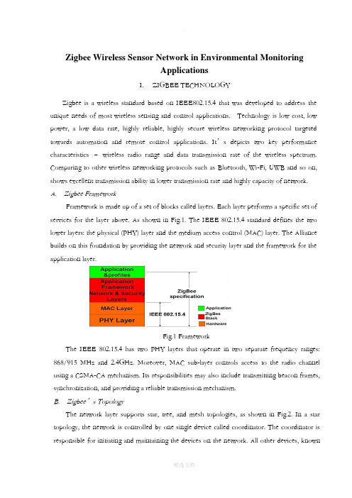
Zigbee Wireless Sensor Network in Environmental MonitoringApplicationsI. ZIGBEE TECHNOLOGYZigbee is a wireless standard based on IEEE802.15.4 that was developed to address the unique needs of most wireless sensing and control applications. Technology is low cost, low power, a low data rate, highly reliable, highly secure wireless networking protocol targeted towards automation and remote control applications. It’s depicts two key performance characteristics –wireless radio range and data transmission rate of the wireless spectrum. Comparing to other wireless networking protocols such as Bluetooth, Wi-Fi, UWB and so on, shows excellent transmission ability in lower transmission rate and highly capacity of network. A. Zigbee FrameworkFramework is made up of a set of blocks called layers.Each layer performs a specific set of services for the layer above. As shown in Fig.1. The IEEE 802.15.4 standard defines the two lower layers: the physical (PHY) layer and the medium access control (MAC) layer. The Alliance builds on this foundation by providing the network and security layer and the framework for the application layer.Fig.1 FrameworkThe IEEE 802.15.4 has two PHY layers that operate in two separate frequency ranges: 868/915 MHz and 2.4GHz. Moreover, MAC sub-layer controls access to the radio channel using a CSMA-CA mechanism. Its responsibilities may also include transmitting beacon frames, synchronization, and providing a reliable transmission mechanism.B. Zigbee’s TopologyThe network layer supports star, tree, and mesh topologies, as shown in Fig.2. In a star topology, the network is controlled by one single device called coordinator. The coordinator is responsible for initiating and maintaining the devices on the network. All other devices, knownas end devices, directly communicate with the coordinator. In mesh and tree topologies, the coordinator is responsible for starting the network and for choosing certain key network parameters, but the network may be extended through the use of routers. In tree networks, routers move data and control messages through the network using a hierarchical routing strategy. Mesh networks allow full peer-to-peer communication.Fig.2 Mesh topologiesFig.3 is a network model, it shows that supports both single-hop star topology constructed with one coordinator in the center and the end devices, and mesh topology. In the network, the intelligent nodes are composed by Full Function Device (FFD) and Reduced Function Device (RFD). Only the FFN defines the full functionality and can become a network coordinator. Coordinator manages the network, it is to say that coordinator can start a network and allow other devices to join or leave it. Moreover, it can provide binding and address-table services, and save messages until they can be delivered.Fig.3 Zigbee network modelII.THE GREENHOUSE ENVIRONMENTAL MONITORINGSYSTEM DESIGNTraditional agriculture only use machinery and equipment which isolating and no communicating ability. And farmers have to monitor crops’ growth by themselves. Even if some people use electrical devices, but most of them were restricted to simple communication between control computer and end devices like sensors instead of wire connection, which couldn’t be strictly defined as wireless sens or network. Therefore, by through using sensor networks and, agriculture could become more automation, more networking and smarter.In this project, we should deploy five kinds of sensors in the greenhouse basement. By through these deployed sensors, the parameters such as temperature in the greenhouse, soil temperature, dew point, humidity and light intensity can be detected real time. It is key to collect different parameters from all kinds of sensors. And in the greenhouse, monitoring the vegetables growing conditions is the top issue. Therefore, longer battery life and lower data rate and less complexity are very important. From the introduction about above, we know that meet the requirements for reliability, security, low costs and low power.A. System OverviewThe overview of Greenhouse environmental monitoring system, which is made up by one sink node (coordinator), many sensor nodes, workstation and database. Mote node and sensor node together composed of each collecting node. When sensors collect parameters real time, such as temperature in the greenhouse, soil temperature, dew point, humidity and light intensity, these data will be offered to A/D converter, then by through quantizing and encoding become the digital signal that is able to transmit by wireless sensor communicating node. Each wireless sensor communicating node has ability of transmitting, receiving function.In this WSN, sensor nodes deployed in the greenhouse, which can collect real time data and transmit data to sink node (Coordinator) by the way of multi-hop. Sink node complete the task of data analysis and data storage. Meanwhile, sink node is connected with GPRS/CDMA can provide remote control and data download service. In the monitoring and controlling room, by running greenhouse management software, the sink node can periodically receives the data from the wireless sensor nodes and displays them on monitors.B. Node Hardware DesignSensor nodes are the basic units of WSN. The hardware platform is made up sensor nodes closely related to the specific application requirements. Therefore, the most important work isthe nodes design which can perfect implement the function of detecting and transmission as a WSN node, and perform its technology characteristics. Fig.4 shows the universal structure of the WSN nodes. Power module provides the necessary energy for the sensor nodes. Data collection module is used to receive and convert signals of sensors. Data processing and control module’s functions are node device control, task sche duling, and energy computing and so on. Communication module is used to send data between nodes and frequency chosen and so on.Fig.4 Universal structure of the wsn nodesIn the data transfer unit, the module is embedded to match the MAC layer and the NET layer of the protocol. We choose CC2430 as the protocol chips, which integrated the CPU, RF transceiver, net protocol and the RAM together. CC2430 uses an 8 bit MCU (8051), and has 128KB programmable flash memory and 8KB RAM. It also includes A/D converter, some Timers, AES128 Coprocessor, Watchdog Timer, 32K crystal Sleep mode Timer, Power on Reset, Brown out Detection and 21 I/Os. Based on the chips, many modules for the protocol are provided. And the transfer unit could be easily designed based on the modules.As an example of a sensor end device integrated temperature, humidity and light, the design is shown in Fig. 5.Fig.5 The hardware design of a sensor nodeThe SHT11 is a single chip relative humidity and temperature multi sensor module comprising a calibrated digital output. It can test the soil temperature and humidity. The DS18B20 is a digital temperature sensor, which has 3 pins and data pin can link MSP430 directly. It can detect temperature in greenhouse. The TCS320 is a digital light sensor. SHT11, DS18B20 and TCS320 are both digital sensors with small size and low power consumption. Other sensor nodes can be obtained by changing the sensors.The sensor nodes are powered from onboard batteries and the coordinator also allows to be powered from an external power supply determined by a jumper.C. Node Software DesignThe application system consists of a coordinator and several end devices. The general structure of the code in each is the same, with an initialization followed by a main loop.The software flow of coordinator, upon the coordinator being started, the first action of the application is the initialization of the hardware, liquid crystal, stack and application variables and opening the interrupt. Then a network will be formatted. If this net has been formatted successfully, some network information, such as physical address, net ID, channel number will be shown on the LCD. Then program will step into application layer and monitor signal. If there is end device or router want to join in this net, LCD will shown this information, and show the physical address of applying node, and the coordinator will allocate a net address to this node. If the node has been joined in this network, the data transmitted by this node will be received by coordinator and shown in the LCD.The software flow of a sensor node, as each sensor node is switched on, it scans all channelsand, after seeing any beacons, checks that the coordinator is the one that it is looking for. It then performs a synchronization and association. Once association is complete, the sensor node enters a regular loop of reading its sensors and putting out a frame containing the sensor data. If sending successfully, end device will step into idle state; by contrast, it will collect data once again and send to coordinator until sending successfully.D. Greenhouse Monitoring Software DesignWe use VB language to build an interface for the test and this greenhouse sensor network software can be installed and launched on any Windows-based operating system. It has 4 dialog box selections: setting controlling conditions, setting Timer, setting relevant parameters and showing current status. By setting some parameters, it can perform the functions of communicating with port, data collection and data viewing。
ZigBee Wireless Networks and Transceivers中文翻译 第一章 ZigBee基础

由于国内暂时还没有该文献的中文版本,而ZigBee Wireless Networks and Transceivers又是ZigBee界的葵花宝典,为了自己更好的学习,所以决定将比较多的蛋疼的时间拿出来做点有意义的事,虽然翻译水平不是很高,但是在翻译的过程中肯定能得到进步,最关键的就是检验自己的毅力,看看能否坚持。
在这个过程中,如果还能帮到一些正在入门ZigBee的朋友那就更好了。
废话不多说,开始ZigBee Wireless Networks and TransceiversZigBee无线网络和收发器1第一章ZigBee基础本章主要介绍了短距离无线网络通信的ZigBee标准,本章的主要目的就是对ZigBee的基础特性进行一下简单的概述,包括它的网络拓扑、信道访问机制和每个协议层所扮演的角色,在后续章节中对本章所讨论的内容有详细的解释。
1.1 什么是ZigBee?ZigBee是为低数据速率、短距离无线网络通信定义的一系列通信协议标准。
基于ZigBee的无线设备工作在868MHZ, 915MHZ和2.4Z频带。
其最大数据速率是250Kbps. ZigBee技术主要针对以电池为电源的应用,这些应用对低数据速率、低成本、更长时间的电池寿命有较高的需求。
在一些ZigBee应用中,无线设备持续处于活动状态的时间是有限的,大部分时间无线设备是处于省电模式(也称休眠模式)的。
因此,ZigBee设备在电池需要更换以前能够工作数年以上。
ZigBee的其中一个应用就是室内病人监控。
例如,一个病人的血压,心率可以通过可穿戴设备测量出来,病人戴的ZigBee设备来周期性的收集血压等健康相关的信息,然后这些数据被无线传送到当地服务器,例如病人家中的一台个人电脑,电脑再对这些数据进行初始分析,最后重要的信息通过互联网被发送到病人的护士或者内科医生那里做进一步的分析。
另一个ZigBee的应用例子就是大型楼宇结构安全的监控。
study on Zigbee

Impact Factor: 1.852 IJESRTINTERNATIONAL JOURNAL OF ENGINEERING SCIENCES & RESEARCHTECHNOLOGYStudy on ZIGBEE TechnologyAbhishek Kumar*1, Sandeep Gupta2*1,2Department Of ECE, Bharat Institute of Technology, Partapur, Meerut-250003, India999electro.abhi@AbstractZIGBEE is one of the most widely used transceiver standard in wireless sensor networks. Zigbee over IEEE 802.15.4., defines specifications for low rate WPAN(LR-WPAN) to support lower monitoring and controlling devices. Zigbee is developed by Zigbee alliance ,which has hundreds of member companies. Zigbee alliance(software) defines the network, security and application layers. IEEE802.15.4(hardware) defines the physical and media access control layers for LR-WPAN. This paper presents a detailed study of Zigbee wireless standard, IEEE802.15.4 specification, Zigbee device types, the protocol stack architecture and its application.Keywords: Zigbee, IEEE802.15.4. Standard, LR-WPAN.IntroductionWireless Technology is being developed rapidly nowadays. Advancement in micro electromechanical systems brings integration of sensing, signal processing and RF capability on very small devices. All kind of portable applications tend to be able to communicate without the use of any wires. Aim of wireless communication is to gather information or perform certain task in the environment. A typical sensor node contains three C’s, are Collection, Computation and Communication units. Based on the request of sink, gathered information will be transmitted wirelessly. The collection unit has series of sensors. Computation unit contains microcontroller and memory. Finally the communication unit contains transceiver to transmit and receive data; various transceivers (such as RFM TR1000 family, Hardware accelerators, ChipconCC1000 and CC2420 family , Infineon TDA 525x family, IEEE802.15.4/Ember EM2420 RF transceiver, ConexantRDSSS9M) used for this purpose.The reasons [1] for using Zigbee are,•Reliable and self healing• Supports large number of nodes.•Easy to deploy•Very long battery life•Secure•Low cost•Can be used globally• Vibrant industry support with thirty or more vendors supplying products and services •Open Standards protocol with no or negligible licensing fees•Chipsets available from multiple sources•Remotely upgradeable firmware• No new wires•Low power (ability to operate on batteriesmeasured in years)•Low maintenance (meshing, self organizing)•Standards based security [AES128]•Ability to read gas metersAll of the technologies are young – Bluetooth being the oldest with developments started in 1997. ZigBee started its developments in 2001. Different companies developed other technologies within the last three or four years. Zigbee is one of the most widely utilized Wireless Sensor Network standards with low power, low data rate, low cost and short time delay characteristics, simple to develop and deploy and provides robust security and high data reliability. Name of the Zigbee came from zigzagging patterns of honey bees between flowers, represents the communication between nodes in a mesh network [1].ZIGBEE and IEEE 802.15.4ZigBee is developed by ZigBee alliance, which has hundreds of member companies (Ember, Freescale, Chipcon, Invensys, Mitsubishi, CompXs, AMI Semiconductors, ENQ Semi conductors), from semiconductor and software developers to original equipment manufacturers. ZigBee and 802.15.4 are not the same. ZigBee is a standard based network protocol supported solely by the ZigBee alliance that uses the transport services of the IEEE802.15.4 networkhttp: // (C) International Journal of Engineering Sciences & Research Technology[2733-2738]specification. ZigBee alliance is responsible for ZigBee standard and IEEE is for IEEE802.15.4. It is like TCP/IP using IEEE 802.11b network specification [2]. ZigBee alliance (software) defines the network, security and application layers. IEEE802.15.4 (hardware) defines the physical and media access control layers for LR-WPAN in figure1. Power needed for ZigBee is very small. In most cases it uses 1mW (or less power). But still it provides range up to 150 meters in outdoor which is achieved by the technique called direct sequence spread spectrum (DSSS). Also DSSS consumes less power compared to Frequency Hopping Spread Spectrum (FHSS). It works in the 868 MHz (Europe),915 MHz (North America and Australia) and 2.4 GHz(available worldwide) ISM band with up to 20kbps, 40kbps and 250kbps data rate respectively .Because these wave bands are different from the bands of current common wireless networks, Wireless Fidelity (Wi-Fi), Bluetooth, Wireless USB etc. Mutual interferences between them will not occur, therefore, this guarantees our system will not interfere other wireless networks and will not be affected as well.Figure 1: ZigBee adds network, security, and application-services layers to the PHY and MAC layers of the IEEE811.15.4 radio.The IEEE 802.15.4 standard employs 64-bit and16-bit short addresses to support theoretically more than 65,000 nodes per network [7]. ZigBee network can have up to 653356 devices, the distance between ZigBee devices can be up to 50 meters, and each node can relay data to other nodes. This leads capability of making a very big network which covering significant distances.ZIGBEE StandardZigBee device are the combination of application (such as light sensor, lighting control etc), ZigBee logical(coordinator, router, end device), and ZigBee physical device types (Full Function Device and Reduced Function Device)[1].A,ZigBee physical device types: Based on dataprocessing capabilities, two types of physical devices are provided in IEEE 802.15.4: Full Function Devices (FFD)and Reduced Function Devices(RFD). Full Function Devices can perform all available operations within the standard, including routing mechanism, coordination tasks and sensing task. The FFD plays role of coordinator or router or end devices (It can be either FFD or RFD depends on its intended application). A typical FFD in a ZigBee network will be powered from an AC-fed mains supply, as it must always be active and listening to the network . Reduced Function Devices, on the other hand,implements a limited version of the IEEE 802.15.4 protocol. The RFDs do not route packets and must be associated with an FFD. These are end devices such as sensors actuators which only doing limited tasks like recording temperature data, monitoring lighting condition or controlling external devices. The current ZigBee standard requires FFDs to be always on, which in practice means that FFDs must be constantly powered. Battery-powered FFDs have a lifetime on the order of a few days. B. ZigBee logical device types :There are three categories of nodes in a ZigBee system.They are Coordinator, Router and End devices. 1) Coordinator : Forms the root of the network tree and might bridge to other networks. There is exactly one coordinator in each network. It is responsible for initiating the network and selecting the network parameters such as radio frequency channel, unique network identifier and setting other operational parameters. It can also store the information about network, security keys.2) Router: Router acts as intermediate nodes, relaying data from other devices. Router can connect to an already existent network, also able to accept connections from other devices and be some kind of re- transmitters to the network. Network may be extended through the use ofZigBee routers.Figure 2: Zigbee Networkhttp: // (C) International Journal of Engineering Sciences & Research Technology[2733-2738]3) End Devices : End Device can be low-power/ battery-powered devices. They can collect various information from sensors and switches. They have sufficient functionality to talk to their parents (either the coordinator or a router) and cannot relay data from other devices. This reduced functionality allows for the potential to reduce their cost. They support better low power models. These devices do not have to stay awake the whole time, while the devices belonging to the other two categories have to. Each end device can have up to 240 end nodes which are separate applications sharing the same radio.C. Access Modes:Two ways of multi-access inZigBee protocol, are Beacon and Non-beacon. In non beacon enabled network, every node in the network can send the data when the channel is free. In beacon enabled network, nodes can only transmit in predetermined time slots. Here PAN coordinator allocates guaranteed time slots (GTS) for each device; therefore devices will transmit their data during their own slot. All devices should be synchronized for this process. This will be achieved by sending beacon signal. The coordinator is responsible to transmit beacon signals to synchronize the devices attached to it [4]. Network in which the coordinator does not transmit beacon signal is known as non-beacon network. It cannot have GTS and contention free periods, because the devices are not synchronized. Battery life is better than beacon enabled network, because the devices are wake up less often.ZIGBEE Protocols StackProtocol architecture is based on Open systeminterconnection (OSI). ZigBee builds on IEEE standard 802.15.4 which defines the physical and media access control (MAC) layers.ZigBee alliance defines the network layer andapplication layer. Fig.2 shows protocol stack of ZigBeesystem.Figure 3. ZigBee Protocol StackA. Physical Layer: The physical layer of the IEEE802.15.4 standard is the closest layer to the hardware, which control and communicate with the radio transceiver directly. It handles all tasks involving the access to the ZigBee hardware ,including initialization of the hardware, channel selection ,link quality estimation, energy detection measurement and clear channel assessment to assist the channel selection. Supports three frequency bands, 2.45GHz band which using 16 channels, 915MHz band which using 10 channels and 868MHz band using 1 channel. All three using Direct Spread Spectrum Sequencing (DSSS) access mode.Parameters/frequency 868Mhz 915Mhz 2450Mhz Channels 1 10 16 Data rate 20Kbps 40Kbps 250Kbps Applicability Europe USA WorldB. MAC Layer: This layer provides interface between physical layer and network layer. This provides two services; MAC data services and MAC management service interfacing to the MAC sub Layer Management Entity (MLME) Service Access Point called (MLME-SAP). The MAC data service enables the transmission and reception of MAC Protocol Data Units (MPDUs) across the PHY data service. MAC layer is responsible for generating beacons and synchronizing devices to the beacon signal in a beacon enabled services. It is also performing association and dissociation function. It defines four frame structures, are Beacon frame, Data frame, Acknowledge frame, MAC command frame. Basically there are two types of topology; star and peer to peer. Peer to peer topology can take different shapes depends on its restrictions. Peer to peer is known as mesh, if there is no restriction. Another form is tree topology. Interoperability is one of the advantages of ZigBee protocol stack. ZigBee has wide range of applications, so different manufacturer provides ZigBee devices. Z igBee devices can interact witheach other regardless of manufacturer (even if the message is encrypted).C. Network Layer: Network layer interfaces between application layer and MAC Layer. This Layer is responsible for network formation and routing. Routing is the process of selection of path to relay the messages to the destination node. This forms the network involving joining and leaving of nodes, maintaining routing tables (coordinator/router), actual routing and address allocation. ZigBee coordinator or router will perform the route discovery. This layer Provides network wide security and allows low power devices to maximize their battery life. From the basic topologies, there are threehttp: // (C) International Journal of Engineering Sciences & Research Technology[2733-2738]network topologies are considered in IEEE802.15.4 arestar, cluster tree and mesh.D. Application Layer: The application Layer is thehighest protocol layer and it hosts the application objects.ZigBee specification separates the APL layer into threedifferent sub-layers: the Application Support Sub layer, the ZigBee Device Objects, and Application Frameworkhaving manufacturer defined Application Objects.1) The application objects (APO) : Control and managesthe protocol layers in ZigBee device. It is a piece ofsoftware which controls the hardware. Each applicationobjects assigned unique end point number that otherAPO’s can use an extension to the network deviceaddress to interact with it [6]. There can be up to 240application objects in a single ZigBee device. A ZigBeeapplication must conform to an existing applicationprofile which is accepted ZigBee Alliance. Anapplication profile defines message formats andprotocols for interactions between application objects.The application profile framework allows differentvendors to independently build and sell ZigBee devicesthat can interoperate with each other in a, givenapplication profile.2) ZigBee Device Object: The key definition of ZigBeeis the ZigBee device object, which addresses three mainoperations; service discovery, security and binding. Therole of discovery is to find nodes and ask about MACaddress of coordinator/router by using uncast messages.The discovery is also facilitating the procedure forlocating some services through their profile identifiers. So profile plays an important role. The security services in this ZigBee device object have the role to authenticate and derive the necessary keys for data encryption. The network manager is implemented in the coordinator and its role is to select an existing PAN to interconnect. It also supports the creation of new PANs. The role of binding manager is to binding nodes to recourses and applications also binding devices to channels [5].3) Application support sub layer: The ApplicationSupport (APS) sub layer provides an interface betweenthe NWK and the APL layers through a general set ofservices provided by APS data and management entities. The APS sub layer processes outgoing /incoming framesin order to securely transmit/receive the frames andestablish/manage the cryptographic keys. The upperlayers issue primitives to APS sub layer to use itsservices. APS Layer Security includes the followingservices: Establish Key, Transport Key, Update Device,Remove Device, Request Key, Switch Key, EntityAuthentication, and Permissions Con guration Table.4) Security service provider: ZigBee provides security mechanism for network layer and application support layers, each of which is responsible for securing their frames. Security services include methods for key establishment, key transport, frame protection and device management.E. Topologies: There are following topologies (1)Star Topology: Star topology consists of one coordinator and any number of end devices. In star topology a master slave network model is adopted where master is the ZigBee coordinator which is FFD and slave will be either FFD or RFD. ZigBee end devices are physically and electrically separated from each other end devices and pass information through coordinator. Devices can only communicate with the coordinator. This is does not provide multi-hop networking and mesh networking. (2)Cluster Tree Topology: The cluster tree topology is similar to the star topology. The difference is that other nodes can communicate with each other so that more RFD/FFDs can be connected to non-coordinator FFDs. The advantage of this topology is the possible geographical expansion of network. (3)Mesh Topology: In mesh topology, each node can communicate any other node within its range. Mesh topology is complex to maintain and beaconing is not allowed here. But it is more robust and tolerance to fault.Figure 4: topologiesZIGBEE ApplicationZigbee Alliance targets applications “acrossconsumer, commercial, industrial and governmentmarkets worldwide”. Unwired applications are highlysought after in many networks that are characterized bynumerous nodes consuming minimum power andenjoying long battery lives.http: // (C) International Journal of Engineering Sciences & Research Technology[2733-2738]Zigbee technology is designed to best suit these applications ,for the reason that it enables reduced costs of development, very fast market adoption, and rapid ROI.Airbee Wireless Inc has tied up with Radio craft AS to deliver “Zigbee-ready solutions; the former supplying the software and the latter making the module platforms .With even light controls and thermostat producers and includes big OEM names like HP ,Philips,Motorola and Intel.With Zigbee designed to enable two-way communication , not only will the consumer be able to monitor and keep track of domestic utilities usage, but also feed it to a computer system for data analysis.Futurists are sure to hold Zigbee up and says,” See I told you so”. The Zigbee Alliance is nearly 200 strong and growing, with more OEM’s signing up. This means that more and more products and even later, all devices and their controls will be based on this standard. Since Wireless personal Area Networking applies not only to household devices, but also to individualized office automation applications, Zigbee is here to stay .It is more than likely the basis of future home-networking solutions.Table 1 Application of ZigbeeComparison to Blue ToothZigbee was developed t serve very differentapplications than Bluetooth and leads to tremendous optimizations in power consumption. Some of the key differentiators are :(a) Zigbee: It has very low duty cycle, very long primary battery life ,Static and Dynamic star and mesh networks,>65,000 nodes, with low latency available, Ability to remain quiescent for long periods without communications, Direct Sequence Spread spectrum allows devices to sleep without the requirement for close synchronization.(b) Bluetooth: It has Moderate duty cycle ,secondary battery lasts same as master, very high QoS and very low, guaranteed latency, Quasi –static star networks up to seven clients with ability to participate in more than one network, Frequency Hopping Spread Spectrum is extremely difficult to create extended networks without large synchronization cost.Advantages of ZIGBEEThe main advantages include productinteroperability, vendor independence, and accessibility to broader markets. Customers can expect increased product innovation as a result of the industry standardization of the physical radio and logical networking layers. Instead of having to invest resources to create a new proprietary solution from scratch every time, companies will now be able to leverage these industry standards to instead focus their energies on finding and serving customers. the United States. This specification maintains the same usage and architecture as wired USB devices with a high-speed host-to-device connection and connects to a maximum of 127 devices. WUSB is based on a hub and spoke topology.ConclusionThe main conclusion of this Master’s thesis project is that, yes, ZigBee is a suitable base for embedded wireless development. The main reason is that development is easy and fast. ZigBee also meets the promised technical requirements. The areas that ZigBee is likely to be used in is building automation and industrial networks. The chances seem highest in the industry since ZigBee is currently the only option for such standardized wireless networks. Even though there are some competition, due to better performance, price and compliance, ZigBee is likely to dominate the home automation market as well. PC peripherals and consumers electronics are two areas that ZigBee is very unlikely to be used in, because it offers very little over the competition.“Just as the personal computer was a symbol of the '80s, and the symbol of the '90s is the World Wide Web, the next nonlinear shift, is going to be the advent of cheap sensors.”References[1].[2]"Hands-on ZigBee: implementing 802.15.4 withmicrocontrollers" Fredeady[3]ZigBee-2007 security essentials ender y¨ ukselhanne riis nielson flemming nielson informaticsand mathematical modelling, technicaluniversity of denmark richard petersens pladsbldg 321, dk-2800 kongens lyngby, Denmark[4]Shahin farahani, "ZigBee wireless networks andtransceivers"[5]H. labiod,h. afifi,c. de santis "wi-fitm,bluetooth,zig bee and wimax".[6]Wireless sensor networks: a survey on the stateof the art and the 802.15.4 and ZigBee standardspaolo baronti, prashant pillai, vince chook ,stefano chessa , alberto gotta, y. fun hu.[7]Khanh tuan le. designing a ZigBee-ready ieee802.15.4-compliant radio transceiver. chipcon,11/2004.[8]Protocols and architectures for wireless sensornetworks holger karl university of paderborn,germany andreas willig hasso-plattnerinstitute atthe university of potsdam, germany[9]Segolene arrigault, vaia zacharaki. ” Design of aZigBee magnetic sensor node” Master ofScience thesis.[10] “Part 15.4: Wireless Medium Access Control(MAC) and Physical Layer (PHY)Specifications for Low-Rate Wireless PersonalArea Networks (LR-WPANs) “SponsorLAN/MAN Standards Committee of the IEEEComputer Society.http: // (C)International Journal of Engineering Sciences & Research Technology[2733-2738]。
ZigBee外文文献加翻译

A Coal Mine Environmental Monitor System with LocalizationFunction Based on ZigBee-Compliant PlatformDongxuan YangCollege of Computer and InformationEngineeringBeijing Technology and BusinessUniversityBeijing, ChinaYan ChenCollege of Computer and InformationEngineeringBeijing Technology and BusinessUniversityBeijing, China*****************Kedong WangCollege of Computer and InformationEngineeringBeijing Technology and BusinessUniversityBeijing, ChinaAbstract—This paper describes and implements a new type of coal mine safety monitoring system, it is a kind of wireless sensor network system based on ZigBee technology. The system consists of two parts underground and surface. Wireless sensor networks are constituted by fixed nodes, mobile nodes and a gateway in underground. PC monitoring software is deployed in the surface. The system can not only gather real-time environmental data for mine, but also calculate the real-time location of mobile nodes worn by miners.Keywords:ZigBee; localization; wireless sensor networks; coal MineI.RESEARCH STATUSAs an important energy, coal plays a pivotal role in the economic development. Coal mine monitoring system, is the important guarantee for coal mine safety and high efficiency production [1]. In order to ensure the safe operation, the installation of environment monitoring node in tunnels to real-time detection is very important. However, commonly used traditional monitoring node wired connection to obtain communication with the control system, this node exist wiring difficulties, expensive and other shortcomings. In contrast, wireless sensor node can be easily with current mine monitoring network connection, and good compatibility, facilitate constituted mine gas monitoring network, to suit various size of mine applications. Since wireless nodes are battery powered, so completely out of the shackles of the cable, shorten the construction period can be arranged at any time where the need to use.The ZigBee wireless communication technology is used in this coal mine environmental monitor system. This is a new short-range, low complexity, low power,low data rate, low-cost two-way wireless communication technology [2]. Now, wireless sensor network product based on ZigBee technology are quantity and variety, but the real product can be applied in underground environments of special sensor node is very few[3]. The sensor node that we designed in the system is truly able to apply to in-well environment, it through the wireless sensor node security certification. At the same time, due to the special nature of the wireless network is that it can spread the wireless signal, we can easily locate staff for coal mine safety monitoring provides more protection [4].II. SYSTEM ARCHITECTUREThis system is a comprehensive monitoring system which is combined with software and hardware. Hardware part includes wireless mobile nodes and fixed nodes which were deployed in the underground tunnel, the main function of them is to collect coal mine environment data and require person’s location. Software part refers to the PC monitoring software which is designed in VC++ is used to summarize and display the data of each node. Monitoring node is divided into mobile nodes and fixed nodes; they are using ZigBee protocol for wireless transmission of data. Because the fixed node is also using wireless data transmission method, so it's deployed in the underground roadway becomes very convenient. As the mobile node is carried by the miner, it must be using wireless transmission method. This allows the mine to form a topology of ZigBee wireless sensor network. The fixed node in wireless sensor network is router device and the mobile node carried by miner is the end device. Normally, the router of ZigBee network has no sensor equipment; it is only responsible for data forwarding. But considering the practical application, we believe that add sensor devices on the router will be better on monitoring underground coal mine environment. So in our design, the router also has an environment monitoring function which is usually designed in end device.Fixed node will sent received data from mobile node to the gateway, then the gateway transmits data to monitor computer through RS232 or optical fiber. The PC monitor software in the computer will process all data and display them in a visualization window. The PC software also calculates each mobile node’s real-time location through the specific localization algorithm, according to the received signal strength (RSSI) obtained from mobile nodes.III. NODE DESIGNSince the ZigBee wireless network platform sold on present market was designed for the general environment, for special underground so they are not suitable for the environment. Therefore, we need to customize the system for underground environment whit a special hardware circuit. Node photo are shown in Fig. 1 Then wireless microcontroller CC2530 chip is the core processor of the node device, it can constitute a ZigBee network with very few peripheral circuits. TheCC2530 is an IEEE 802.15.4 compliant true System-on-Chip, supporting theproprietary 802.15.4 market as well as the ZigBee, ZigBee PRO, and ZigBee RF4CE standards. Unlike other wireless chip, CC2530 built-in 8051 monolithic integrated circuits kernel, therefore we no longer need to use a single MCU to control the circuit, and this save us a lot of cost [5].A.Mobile NodeThe mobile node is the end device of a ZigBee network that can be carried by miner; it should be a portable and low power consumption node. So the mobile node we designed is only as small as a mobile phone, and it is by built-in lithium ion battery power supply. In power loss, the core processor CC2530 is a low power consumption chip, when it is in the sleep mode, it only need to use less then 1uA work current. In order to reduce power consumption as much as possible on the display, a 100*32 pixel matrix with no backlighting LCD screen was used. The battery’s capacity of the mobile node is 1500mAh,so it is enough to meet the miner’s long hour works in the underground. The battery charge management chip is TP4057, the maximum charge current can up to 500Ma.Figure 1. Node photo.The mobile node circuit includes the gas concentration sensor MJ4.0 and temperature sensor PT-1000. As far as we know, many wireless sensor platforms use the digital type sensor. The communication between the digital sensor and the MCU need strict timing requirements. But considering the actual application, the wireless MCU usually has a real-time operating system in general, if we use the microcomputer to simulate the strict timing, it will affect the real-time of whole operating system. These two sensors output analog signals not digital signals. Only input this signal into a differential amplifier, can we get an appropriate signal that can be converted to a digital signal by an ADC mode within the CC2530 chip. In order to facilitate the carrying, external antenna was not used in our mobile node, instead ofusing a 2.4GHz patch antenna. And we customize a shell like a cell phone size; it is enough to put all PCBs, sensors and battery in it. Taking into account the small shell of the explosive performance is not very good, the design of PCBs and the selection of component are all carried out the safety assessment.B. Fixed NodeFixed node is installed in the wall of the underground tunnel. Because it is big than the mobile node, it is not appropriate to carry around. The circuit of the fixed node is almost same with the mobile node, it also use a CC2530 chip as core processor. Because of underground tunnels generally deploy with power cable, fixed nodes can use cable power-supply modes. At the same time, because we use wireless signal transmission, the deployment of new fixed nodes become very convenient, which also resolves the problem of the signal lines deployment.As a fixed node, the minor who is doing work may far from it, in order to facilitate the miners observed environmental data around the fixed nodes, it uses LED digital display. At the same time, the large current LED lights and buzzer are designed in the circuit; it makes the fixed node with the function of sound-light alarm. Considering that it may occur the emergency of without electricity, fixed node also built-in a lithium-ion battery. Under normal conditions, lithium-ion battery is in charging status, when external cable disconnect, fixed node is automatic switched to battery power, which can ensure the mobile node can deliver the information through fixed nodes in underground.Without regarding to fixed nodes’ portability, we have a customized shell that has excellent explosion properties, and the internal space is enough to hold down the 2.4 GHz antenna. To ensure safety, all cables and the location of sensors are placed with particular glue sealed, so that it has a good seal.IV.POSITIONING FUNCTIONOne of the important functions of the wireless sensor networks is localization, especially in the underground tunnel, it relates to the safe of the miner's life. Currently most widely used orientation method is GPS satellite positioning, it is a high precision, all-weather and global multifunctional system with the function of radio navigation, positioning and timing. But the GPS positioning method is not suitable for the underground work environment of coal mine, once you enter the underground, it cannot receive satellite signal, thus unable to achieve targeting [6]. We need to consider how to use wireless network to realize positioning function, means using wireless signal between the communications of devices for positioning. The existing distance measuring technology between the wireless-devices basically is the following kinds of methods: TOA, TDOA, AOA and RSSI.About the TOA method, the distance between the two devices is determined by the product of the speed of light and transmission time [7]. Although the precision of this method is accurate, but it require a precise time synchronization, so it demand hardware is higher.TDOA technology need ultrasonic signal,which is setting on a node with receive and transmit function. When measure the distance, it can sent ultrasonic wave and wireless signals together. By measuring the difference between two signals arrival time, we can calculate the distance between two devices [8]. Using this method can also obtain accurate result, but the method need to increase ultrasonic sending and receiving device on the node circuit, it will increase cost.AOA technology needs to install multiple antennas through the nodes so it canobtain adjacent nodes’ signals on deferent directions [9]. With this it can determine the location information from number of adjacent nodes and calculate its own position. This method not only need to add additional hardware, but also it's still very vulnerable to external disturbance, therefore it's not suitable for utilize.RSSI ranging is a cheap and easy technology. By using this method, we don't need to add additional hardware design. We also do not need very precise time requirements. This technique is about with measuring the wireless signals strength in the propagation of the loss, to measure the distance between two nodes. Because of this method requires hardware equipment is less, algorithm is simple, so it has been using in many wireless communication field. Comprehensive all conditions, positioning on the use of RSSI ranging technique.A. Hardware Location EngineThe CC2431 wireless microcontroller chip produced by TI Company has a hardware location engine. From the software's point of view, CC2431’s hardware location engine has a very simple API interface, as long as writing the necessary parameters and waiting for calculation, it can read the location results [10].The hardware location engine is also based on RSSI technology. The localization system includes reference nodes and blind nodes. The reference node is a fixed node that located in a known position, the node know their place and send a packet notifyto other nodes. The blind node receives packets from reference nodes, which can obtains reference nodes’ location and the corresponding RSSI value and put them into the hardware location engine, and then the blind node’s location can be read from the engine [11].On the surface, using the CC2431 hardware location engine targeting the program as a good choice, but considering the practical application, it will encounter the following problems. First of all, we have choose the CC2530 as the main chip of fixed nodes of the system, its internal programs is running in ZigBee2007 protocol, but CC2431 as a early chip, it applies only to ZigBee2006 protocol. In the communications between CC2431 and CC2530 that will have compatibility problems. Secondly, CC2431 hardware location engine use the distributed computing, all mobile nodes’ location are calculated by themselves, and then they upload information to the gateway node, this will not only occupy the mobile node processing time, still it can take up more network resources. For this reason, we have to shelve this approach, consider how to implement location by using CC2530 chip.B. Software Location EngineIf we want to use CC2530 to implement location function, that we must write software location engine by ourselves. Because that chip do not have a hardware location engine inside of it. This software location engine is still used RSSI technology; meanwhile mobile node position is calculated by the PC software, so asto reduce the burden of mobile node computing. To calculate the mobile node location, there must be at least three reference nodes. We will regard router nodes as reference nodes in network, and record the X, Y coordinates of every reference node. Then we let the mobile node send signal to each reference node, so that each reference node can obtain a RSSI values, with these parameters, we can use trilateral measurement method to calculate the specified location of the mobile node. The simpler way give the mobile node to broadcast way to send data, then around it every router node would receive the data from the mobile node, thus obtains RSSI values. Once the mobile node number increasing network, this method will make router nodes more burden, because the every radio message that the router node receives will transmit from the low layer to the top layer. Finally the application layer will analyze data packets. Infact, the mobile node need not to broadcast transmitted data, other routing node can also receive the mobile node packets. Only child mobile nodes of the router node will continue to transmit the packet forwarding upward, the other router nodes will shield out the packet in the bottom of the protocol.In order to let all router nodes can receive the packet which sending by mobile nodes, and send its RSSI values up to the gateway node, we need to modify the relevant function in Z- Stack protocol which is provided by TI. First we find the function named afIncomingData, it deals with the received data from the bottom of protocol, in which we add some code that can obtain packet’s RSSI value. Then through the osal_set_event function to add and send an eventMY_RSSI_REPORT_EVT of RSSI value task to OSAL polling system. This event’s corresponding function will be executed in the task of OSAL interrupt-driven function, thus the mobile node corresponding RSSI values will be sent to gateway node. Through this method, the packet will only be processed by bottom function of the protocol. According to this method we can obtain corresponding RSSI value and save the computation time of mobile nodes.In fact, this software location engine is not implementing with a single mobile node, but through the operation of the whole system to achieve. By which the mobile node is only responsible for sending unicast packets. The mobile node’s parent router node is responsible to forward the packet to the gateway. Other router nodes are not responsible for forwarding this packet, just clipping the mobile node of RSSI value, then forwarded to the gateway. Finally the gateway bring all RSSI values of the mobile node to PC monitoring software, the corresponding mobile node’s location is calculated. In order to reduce the error, monitoring software will collect 10 times of the RSSI value and take average on it, and then select the nearest value of the three fixed nodes. Finally the trilateral measurement method is used to calculate the location of mobile nodes.V.SYSTEM IMPLEMENTATIONAll software systems embedded in nodes are based on Z-Stack. BecauseZ-Stack is an open-source project, it is very beneficial to the secondary development. These nodes were tested in a real coal mine locate in Shanxi Province. We deployed the fixed node every 50 meters in the tunnel, and also set a fixed node in each entrance of the work area. Because the fixed node have large size digital LED displays, so the display content of the fixed node can be seen far from away the miner. Each miner carries a mobile node, the temperature and gas concentration is displayed on the LCD screen at real-time.The gateway node is placed at the entrance of the mine, through the RS232 cable connected to the monitoring computer in the control room. In this system all packets collected by the gateway node are transmitted to PC through a serial port, and it can save historical data backup to a SQL database. The main function of monitoring software is to display and store the data of every node, and calculates related mobile nodes’ location according to RSSI values. The monitoring software has two main dialog interfaces, one is used to display a two- dimensional profile of the coal mine, and user can see all the miners' working position. Another interface is data displaying interface, and environmental data were shown here. The picture of PC monitoring software is shown in Fig. 2.Figure 2. PC monitoring software.VI.SYSTEM EV ALUATIONThrough repeated testing of the system, we made the system an objective assessment. First is the power consumption assess for node hardware, fixed node’s working voltage is in 9V ~ 24V when the power supplied by cable. The maximum operating current for fixed node is 93mA; the average operating current is 92.2mA. When the power cable was disconnected, fixed node powered by lithium-ion battery. On battery power, the fixed node’s maximum working current is 147mA; average working current is 146.3mA. Fixed nodes can work 8 hours on battery power at least.Another quite important performance is the location function of the system performance. At four different locations of tunnel and working areas, mobile nodes were placed there. Two sets of different average error data were shown in From table 1. Because this system uses RSSI technology and it relies mainly on the signal strength, the signal quality will be affected by interferences. From different locations’ errors we can see that, the error in working areas was larger than it in tunnels, because the tunnel is generally straight, but the shape of the working areas are uncertainty.We gratefully acknowledge Texas Instruments for devices provided to us free of charge. And also thank staffs of XinNuoJin Company for giving us supports onsystem testing.REFERENCES[1] Xinyue Zhong Wancheng Xie. “Wireless sensor network in the coal mineenvironment monitoring“. Coal technology, 2009, Vol. 28, No. 9,pp.102-103. [2] Shouwei Gao. “ZigBee Technology Practice Guide”. Beijing: Beijing Universityof Aeronautics and Astronautics Press , 2009, pp. 27-28.[3] Yang Wang, Liusheng Huang, Wei Yang. “A Novel Real-Time CoalMinerLocalization and Tracking System Based on Self-Organized Sensor Networks”.EURASIP Journal onWireless Communications and Networking, Volume 2010, Article ID 142092.[4] Sang-il Ko, Jong-suk Choi, Byoung-hoon Kim. “Indoor Mobile LocalizationSystem and Stabilization of Localizaion Performance using Pre-filtering”.International Journal of Control, Automation and Systems, Vol. 6, No. 2, pp.204-213, April 2008.[5] .[6] Hawkins Warren, Daku Brian L. F, Prugger Arnfinn F. “Positioning inunderg round mines”. IECON 2006 - 32nd Annual Conference on IEEE Industrial Electronics, 2006, pp. 3159-3163.[7] Zhu, Shouhong, Ding, Zhiguo, Markarian Karina. “TOA based jointsynchronization and localization”. 2010 IEEE International Conference on Communications, ICC 2010, 2010, Article ID 5502036.[8] Ni Hao, Ren Guangliang, Chang Yilin. “A TDOA location scheme in OFDMbased WMANs”. IEEE Transactions on Consumer Electronics,2008, Vol. 54, No. 3, pp. 1017-1021.[9] Dogançay Kutluyil, Hmam Hatem. “Optimal angular sensor separation for AOAlocalization”. Signal Processing, 2008, Vol. 88, No. 5, pp. 1248-1260.[10] K. Aamodt. “CC2431 Location Engine”. Texas Instruments, Application NoteAN042, SWRA095.[11] Tennina Stefano, Di Renzo Marco, Graziosi Fabio, Santucci Fortunato.“Locating zigbee nodes using the tis cc2431 location engine: A testbed platform and new solutions for positioning estimation of wsns in dynamic indoor environments”. Proc Annu Int Conf Mobile Comput Networking, 2008, pp.37-42.摘要-本文介绍并设计了一个新类型的煤矿安全监控系统,它是一种基于ZigBee 技术的无线传感器网络系统。
ZigBee 中文翻译译文 含外文原文

毕业设计(论文)译文及原稿免费下载,免费分享。
让论文写得更简单,更舒适。
更容易……译文题目ZigBee:无线技术,低功耗传感器网络原稿题目ZigBee: Wireless Technologyfor Low-Power Sensor Networks原稿出处电子文献ZigBee:无线技术,低功耗传感器网络加里莱格美国东部时间2004年5月6日上午12:00技师(工程师)们在发掘无线传感器的潜在应用方面从未感到任何困难。
例如,在家庭安全系统方面,无线传感器相对于有线传感器更易安装。
而在有线传感器的装置通常占无线传感器安装的费用80%的工业环境方面同样正确(适用)。
而且相比于有线传感器的不切实际甚至是不肯能而言,无线传感器更具应用性。
虽然,无线传感器需要消耗更多能量,也就是说所需电池的数量会随之增加或改变过于频繁。
再加上对无线传感器由空气传送的数据可靠性的怀疑论,所以无线传感器看起来并不是那么吸引人。
一个低功率无线技术被称为ZigBee,它是无线传感器方程重写,但是。
一个安全的网络技术,对最近通过的IEEE802.15.4无线标准(图1)的顶部游戏机,ZigBee的承诺,把无线传感器的一切从工厂自动化系统到家庭安全系统,消费电子产品。
与802.15.4的合作下,ZigBee提供具有电池寿命可比普通小型电池的长几年。
ZigBee设备预计也便宜,有人估计销售价格最终不到3美元每节点,。
由于价格低,他们应该是一个自然适应于在光线如无线交换机,无线自动调温器,烟雾探测器和家用产品。
(图1)虽然还没有正式的规范的ZigBee存在(由ZigBee联盟是一个贸易集团,批准应该在今年年底),但ZigBee的前景似乎一片光明。
技术研究公司In -Stat/MDR在它所谓的“谨慎进取”的预测中预测,802.15.4节点和芯片销售将从今天基本上为零,增加到2010年的165万台。
不是所有这些单位都将与ZigBee结合,但大多数可能会。
无线微传感器中英文对照外文翻译文献

无线微传感器中英文对照外文翻译文献(文档含英文原文和中文翻译)A Simple Energy Model for Wireless Microsensor TransceiversAbstract—This paper describes the modelling of shortrange transceivers for microsensor applications. A simple energy model is derived and used to analyze the transceiver battery life. This model takes into account energy dissipation during the start-up, receive, and transmit modes. It shows that there is a significant fixed cost in the transceiver energy consumption and this fixed cost can be driven down by increasing the data rate of the transceiver.I. IntroductionWireless microsensor networks can provide short-range connectivity with significant fault tolerances. These systems find usage in diverse areas such as environmental monitoring, industrial process automation, and field surveillance. As an example, Table I shows a detailed specification for a sensor system used in a factory machine monitoring environment.The major characteristics of a microsensor system are high sensor density, short range transmissions, and low data rate. Depending on the application, there can also be stringent BER and latency requirements. Due to the large density and the random distributed nature of these networks, battery replacement is a difficult task. In fact,a primary issue that prevents these networks to be used in many application areas is the short battery life. Therefore, maximizing the battery life time of the sensor nodes is important. Figure 1 shows the peak current consumption limit when a 950mAh battery is used as the energy source. As seen in the figure, battery life can vary by orders of magnitude depending on the duty cycle of each operation. To allow for higher maximum peak current, it is desirable to have the sensor remain in the off-state for as long as possible.However, the latency requirement of the system dictates how often the sensor needs to be active. For the industrial sensor application described above, the sensor needs to operate every 5ms to satisfy the latency requirement.Assuming that the sensor operates for 100µs every 5ms, the duty cycle is 2%. To achieve a one-year battery life, the peak current consumption must be kept under 5.4mA, which translates to approximately 10mW at 2V supply.This is a difficult target to achieve for sensors that communicate at giga-Hertz carrier frequencies.There has been active research in microsensor networks over the past years. Gupta [1] and Grossglauser [2] established information theoretic bounds on the capacity of ad-hoc networks. Chang [3] and Heinzelman [4] suggested algorithms to increase overall network life-time by spreading work loads evenly among all sensors. Much of the work in this area, especially those that deal with energy consumption of sensor networks, require an energy model [5]. This paper develops a realistic energy model based on the power consumption of a state of the art Bluetoothtransceiver [6]. This model provides insights into how to minimize the power consumption of sensor networks and can be easily incorporated into work that studies energy limited wireless sensor networks. The outline of this paper is as follows. Section II derives the transceiver model. Section III applies this model to analyzing the battery life time of the Bluetooth transceiver.Section IV investigates the dependencies in the model and shows how to modify the design of the Bluetooth transceiver to improve the battery life. Section V shows the battery life improvement realized by applying the results in Section IV. Section VI summarizes the paper.II. Microsensor Transceiver ModellingThis section derives a simple energy model for low power microsensors. Figure 2 shows the model of the sensor node.It includes a sensor/DSP unit for data processing, D/A and A/D for digital-to-analog and analog-to-digital conversion, and a wireless transceiver for data communication. The sensor/DSP, D/A, and A/D operate at low frequency and consume less than 1mW. This is over an order of magnitude less than the power consumption of the transceiver. Therefore, the energy model ignores the contributions from these components. The transceiver has three modes of operation: start-up, receive, and transmit. Each mode will be described and modelled.A. Start-up ModeWhen the transceiver is first turned on, it takes some time for the frequency synthesizer and the VCO to lock to the carrier frequency. The start-up energy can be modelled as follows:where P LO is the power consumption of the synthesizer and the VCO. The term t start is the required settling time. RF building blocks including PA, LNA, and mixer have negligible start-up time and therefore can remain in the off-state during the start-up mode.B. Receive ModeThe active components of the receiver includes the low noise amplifier (LNA), mixer, frequency synthesizer, VCO, intermediate-frequency (IF) amplifier (amp), and demodulator (Demod). The receiver energy consumption can be modelled as follows:where P RX includes the power consumption of the LNA,mixer, IF amplifier, and demodulator. The receiver power consumption is dictated by the carrier frequency and the noise and linearity requirements. Once these parameters are determined, to the first order the power consumption can be approximated as a constant, for data rates up to 10’s of Mb/s. In other words, the power consumption is dominated by the RF building blocks that operate at the carrier frequency. The IF demodulator power varies with data rate, but it can be made small by choosing a low IF.C. Transmit ModeThe transmitter includes the modulator (Mod), frequency synthesizer and VCO (shared with the receiver), and power amplifier (PA). The data modulates the VCO and produces a FSK signal at the desired data rate and carrier frequency. A simple transmitter energy model is shown in Equation (3). The modulator consumes very little energy and therefore can be neglected.P LO can be approximated as a constant. P PA depends on additional factors and needs to be modelled more carefully as follows:where η is the PA efficiency, r is the data rate, d is the transmission distance, and n is the path loss exponent. γPA is a factor that depends on E b /N O , noise factor F of the receiver, link margin L mar , wavelength of the carrier frequency λ, and th e transmit/receive antenna gains G T ,G R :From Equations (3) and (4), the transmitter power consumption can be written as a constant term plus a variable term. The energy model thus becomesIII. Bluetooth TransceiverHere we demonstrate how the above model can be used to calculate the battery life time of a Bluetooth transceiver [6]. This is one of the lowest power Bluetooth transceivers reported in literature. The energy consumption of the transceiver depends on how it operates. Assuming a 100-bit packet is received and a 100-bit packet is transmitted every 5ms, Figure 3 showsthe transceiver activity within one cycle of operation.The transceiver takes 120µs to start up. Operating at 1Mb/s, the receiver takes 100µs to receive the packet. The transceiver then switches to the transmit mode and transmits a same-length packet at the same rate. A 10µs interval, t switch , between the receive and the transmit mode is allowed to switch channel or to absorb any transient behavior. Therefore, the energy dissipated in one cycle of operation is simplyBoth the average power consumption and the duty cycle can be found From Figure 3. Knowing that the transceiver operates at 2V, the life time for a 950mAh battery is calculated to be approximately 2-months.IV. Energy OptimizationThe microsensor system described in Section I requires a battery life of one year or better. Although the Bluetooth transceiver described in the last section falls short of this requirement, it serves as a starting point for making improvements. This section examines E op in detail and suggests ways to increase the battery life by considering both circuit and system improvements. A.Start-up EnergyThe start-up energy can be a significant part of the total energy consumption, especially when the transceiver is used to send short packets in burst mode. For the Bluetooth transceiver, E start accounts for 20% of E op .The start-up energy becomes negligible if the following condition is held true:For the receive/transmit scheme shown in Figure 3, the right hand-side of Equation (8)is evaluated to be approximately 450µs. To keep E start an order of magnitude below E op , it is desirable to have a start-up time of less than 45µs. Cho has demonstrated a 5.8GHz frequency synthesizer im- plementation with a start-up time under 20µs [7].B. Power AmplifierThe PA power consumption is given bywhere η is the power efficiency and P out is the RF output power. P out can be determined by link-budget analysis. For a Bluetooth transceiver, the required P out is 1mW [8].This enables a maximum transmission distance of 10 meters, which is adequate for microsensor applications. Note that P out is small as compared to P LO . The Bluetooth transceiver discussed in Section II has a maximum RF output power of 1.6mW and a PA power consumption of 10mW, sothe efficiency is at 16%. At frequencies around 2GHz, the PA efficiency can vary from 10% [9] to 70% [10] depending on linearity, circuit topology, and technology. Since FSK signal has a constant envelope, nonlinea r PA’s can be used so that better efficiency can be achieved. As will be shown in the next section, PA efficiency has a significant impact on the battery life.C. Data RateAssuming a packet of length L pkt is transmitted at dat rate r, then the transmit time isThe transmitter energy consumption can be re-written asEquation (12) shows that the contribution of the fixed cost P LO can be reduced by increasing the data rate. The energy per bit, E bit , is defined as E op divided by the total number of bits received and sent during one cycle of operation. Assuming a packet of length L pkt is received and a packet of the same length is transmitted, E bit can be found by dividing Equation (7) by 2L pkt . Substituting the appropriate expressions for E start , E rx , and E tx and re-arranging the terms, we getThe first term in Equation (13) is the start-up energy cost. The second term is the PA energy cost. The third term is the cost of the rest of the transceiver electronics during the transmit and receive modes. Note that this term is divided by the data rate r. Figure 4 shows E bit as a function of data rate. The two solid curves have start-up time 120µs and PA efficiencies 10% and 70%, respectively. The two dotted curves have start-up time 20µs and efficiencies 10% and 70%, respectively. At low data rate, E bit is dominated by the fixed cost (the 3rd term in Equation (13)). At high data rate, the start-up energy and the PA energy dominates, so in order to increase battery life, good circuit design techniques need to be applied to minimize the start-up time and to maximize the PA efficiency.Figure 5 shows the impact of PA efficiency on the battery life at a data rate of 10Mb/s. At t start = 120µs, the startup energy is so large that the battery life is limited to 7month even if the PA reaches 100% efficiency. At t start =20µs, the battery life is much improved. The PA efficiency needs to be higher than about 30% to have a 1-year or better battery life. This is certainly achievable as discussed previously in the PA section.V. Performance ImprovementThere are three apparent results from the previous section. First, the data rate should be increased to reduce the fixed cost. Second, the start-up time should be minimized. Third, PA efficiency should be maximized. Figure 6 shows the transceiver activity for a transceiver that has 20µs start-up time and 10Mb/s data rate. The power consumption of the electronics are kept the same as in the Bluetooth transceiver except for the PA. The maximum RF output power is set at 10mW to accommodate the higher data rate, and the PA efficiency is assumed to be 50%. The switching time is kept at 10µs, although this is a conservative since the switching time is likely to be shorter for a faster frequency synthesizer. The E op of this transceiver is 8x lower than that of theBluetooth transceiver. The battery life-time extends from 2-months to approximately1.3 years.VI. ConclusionThis paper describes the modelling of short-range transceivers for wireless sensor applications. This model takes into account energy dissipation during the start-up, transmit, and receive modes. This model is first used to analyze the battery life of a state of the art Bluetooth transceiver, and then it is used to optimize E op . This paper shows that the battery life can be improved significantly by increasing the data rate, reducing the start-up time, and improving the PA efficiency. Increasing the data rate drives down the fixed energy cost of the transceiver. Reducing the start-up time decreases the start-up energy overhead. Improving the PA efficiency lowers the energy per bit cost of the PA.一个简单的能量无线微传感器的接收机模型摘要—本文描述了微传感器的近程的收发器的造型的应用程序。
zigbee-相关-外文资料及翻译教程文件

The APL LayerThe application (APL) layer is the highest protocol layer in a ZigBee wireless network. The ZigBee APL layer consists of three sections, shown in Figure 3.44 : the application support (APS) sublayer, ZigBee Device Objects (ZDO), and the application framework.The application support sublayer (APS) provides an interface between the network layer (NWK) and the application layer (APL). The APS sublayer, similar to all lower layers, supports two types of services: data and management. The APS data service is provided by APS Data Entity (APSDE) and is accessed through the APSDE Service Access Point (SAP). The management capabilities are offered by APS Management Entity (APSME) and are accessed through APSME-SAP.The APS sublayer constants and attributes start with apsc and aps , respectively. The APS attributes are contained in the APS Information Base (APS IB or AIB). The list of APS constants and attributes is provided in the ZigBee specification [3].Network The application framework in ZigBee is the environment in which application objects are hosted to control and manage the protocol layers in a ZigBee device. Application objects are developed by manufacturers, and that is where a device is customized for various applications. There can be up to 240 application objects in a single device.The application objects use APSDE-SAP to send and receive data between peer application objects ( Figure 3.44 ). Each application object has a unique endpoint address (endpoint 1 to endpoint 240). The endpoint address of zero is used for the ZDO. To broadcast a message to all application objects, the endpoint address is set to 255. Endpoint addressing allows multiple devices to share the same radio. In the light control example in Section 2.1.4, multiple lights were connected to a single radio. Each light has a unique endpoint address and can be turned on and off independently.The ZigBee Device Objects (ZDO) provide an interface between the APS sublayer and the application framework. The ZDO contains the functionalities that are common in all applications operating on a ZigBee protocol stack. For example, it is the responsibility of the ZDO to configure the device in one of three possible logical types of ZigBee coordinator, ZigBee router, or ZigBee end device. The ZDO uses primitives to perform its duties and accesses the APS sublayer Management Entity via APSME-SAP. The application framework interacts with the ZDO through the ZDO public interface.The details of application framework, ZDO, and APS sublayer are reviewed in the following three subsections.The Application Framework The ZigBee standard offers the option to use application profiles in developing an application. The use of an application profile allows further interoperability between the products developed by different vendors for a specific application. For instance, in a light control scenario, if two vendors use the same application profile to develop their products, the switches from one vendor will be able to turn on and turn off the lights manufactured by the other vendor. The application profiles are also referred to as ZigBee profiles.Each application profile is identified by a 16-bit value known as a profile identifier . Only the ZigBee alliance can issue profile identifiers. A vendor that has developed a profile can request a profile identifier from the ZigBee alliance. The ZigBee alliance evaluates the proposed application profile and if it meets the alliance guidelines, a profile identifier willbe issued. The application profiles are named after their corresponding application use. For example, the home automation application profile provides a common platform for vendors developing ZigBee-based products for home automation use.The general structure of an application profile is shown in Figure 3.45. The application profile consists of two main components: clusters and device descriptions.A cluster is a set of attributes grouped together. Each cluster is identified by a unique 16-bit number called a cluster identifier . Each attribute in a cluster is also identified by a unique 16bit number known as a attribute identifier . These attributes are used to store data or state values. For example, in a temperature control application, a device that acts as the temperature sensor can store the value of the current temperature in an attribute. Then another device that acts as the furnace controller can receive the value of this attribute and turn on or turn off the furnace accordingly. The application profile does not contain the cluster itself. Instead, the application profile has a list of the cluster identifiers. Each cluster identifier uniquely points to the cluster itself.The other part of an application profile is the device descriptions ( Figure 3.45 ). The descriptions provide information regarding the device itself. For example, the supported frequency bands of operation, the logical type of the device (coordinator, router, or end device), and the remaining energy of the battery are provided by the device descriptions. Each device description is identified by a 16-bit value. The ZigBee application profile uses the concept of descriptor data structure . In this method, instead of including the data in the application profile, a 16-bit value is keptand acts as a pointer to the location of the data. This pointer is referred to as the data descriptor . When a device discovers the presence of another device in the network, the device descriptions are transferred to provide the essential information regarding the new device. The device descriptions consist of five sections: node descriptor, node power descriptor, simple descriptor, complex descriptor, and user descriptor. The node descriptor provides information such as the node logical type and the manufacturer code. The node power descriptor determines whether the device is battery powered and provides the current level of the battery. The profile identifier and clusters are provided in the simple descriptor . The complex descriptor is an optional part of the device descriptions and contains information such as the serial number and the device model name. Any additional information regarding the device can be included as the user descriptor . The user descriptor can be up to 16 ASCII characters. For example, in a light control application, the user descriptor field of a wall switch installed in a hallway can read Hall switch .The node descriptor fields for ZigBee-2006 are provided in Figure 3.46 . The node descriptor is a mandatory part of the device descriptions. The logical type can be ZigBee coordinator, router, or end device. The complex descriptor and user descriptor are optional and if their corresponding fields in the node descriptor are set to zero, they are not provided as part of the device descriptions. The APS flag field determines the APS sublayer capabilities. The frequency band (868 MHz, 915MHz, or 2.4 GHz) is specified in the frequency band field. The MAC capacity flags field is the same as the MAC capacity field presented before in Figure 3.25 . A manufacturer can request and receive a manufacturer code from the ZigBee alliance. This code is included in the node descriptor. The maximum size of the APS Sublayer Data Unit (ASDU), in octets, is specified in the maximum buffer size field. The maximum size of a single message that can be transferred to or from a node is provided in the maximum transfer size field (in octets). In ZigBeePro, the maximum incoming transfer size and maximum outgoing transfer size are two separate fields (16 bits each).The server mask field provides information regarding the system server capabilities of this node. A server is a device that provides specific services to other devices in the network. If each bit is set to one, the device has the corresponding capability shown in Figure 3.46 . The trust center is the device trusted by devices within a network to distribute security keys for the purpose of network and end-to-end application configuration management. The security features are reviewed in Section 3.6. The primary binding table cache is a device that allows other devices to store their binding tables with it as long as it has storage space left. The bindingprocedure is further clarified in this subsection. The primary binding table cache can be used to back up the content of binding tables and restore them whenever necessary.A device can choose to keep its own binding table, known as a source binding table , instead of storing it with a primary binding table cache. However, any device can store a backup of the source binding table in the primary biding table cache device and recover it later if necessary.A ZigBee network may have a primary discovery cache device. This device is a ZigBee coordinator or router used to store the descriptors such as node descriptors and power descriptors of some other devices. An end device, for example, that sleeps for long durations can store its descriptors in the primary discovery cache device. If a device in the network tries to locate the information regarding this sleeping end device while the device is inactive, it can get the information from the primary discovery cache device instead. If a network contains sleeping ZigBee end devices, the network must have at least one primary discovery cache device.应用层(APL)是在ZigBee无线网络协议栈中最高的一层。
- 1、下载文档前请自行甄别文档内容的完整性,平台不提供额外的编辑、内容补充、找答案等附加服务。
- 2、"仅部分预览"的文档,不可在线预览部分如存在完整性等问题,可反馈申请退款(可完整预览的文档不适用该条件!)。
- 3、如文档侵犯您的权益,请联系客服反馈,我们会尽快为您处理(人工客服工作时间:9:00-18:30)。
ZigBee环境监测技术中英文资料对照外
文翻译文献综述
简介
本文综述了有关ZigBee环境监测技术的中英文资料,并提供
了对照的外文翻译文献。
ZigBee是一种低功耗的无线通信技术,特别适用于物联网应用中的环境监测。
通过对这些资料的对比和研究,可以更好地了解和应用ZigBee环境监测技术。
中文资料
1. 许明宝, 胡永凡, 钟红民. 基于ZigBee的环境监测系统研究[J]. 现代检测技术, 2011, 31(1): 5-8.
2. 杨洛, 李明洲. 基于ZigBee的温湿度监测系统设计[J]. 现代电
子技术, 2012(9): 29-32.
3. 谭勇, 王群, 李吉庆. 基于ZigBee的室内环境监测系统设计[J]. 仪器仪表学报, 2015, 36(3): 571-575.
英文资料
1. Wang, X., Hu, Z., & Hang, L. Wireless sensor network-based indoor temperature and humidity monitoring system using ZigBee technology[C]. 2020 6th International Conference on Control, Automation and Robotics (ICCAR), 2020: 100-105.
2. Gao, J., Li, R., & Zhang, L. Study on wireless temperature and humidity monitoring system based on ZigBee[C]. 2019 4th International Conference on Green Technology and Sustainable Development (GTSD), 2019: 1-5.
外文翻译文献
1. 许明宝, 胡永凡, 钟红民. 基于ZigBee的环境监测系统研究(英文翻译). 现代检测技术, 2011, 31(1): 5-8. (Translation of "Research on ZigBee-based Environmental Monitoring System" by Xu Mingbao, Hu Yongfan, and Zhong Hongmin)
2. 杨洛, 李明洲. 基于ZigBee的温湿度监测系统设计(英文翻译). 现代电子技术, 2012(9): 29-32. (Translation of "Design of ZigBee-based Temperature and Humidity Monitoring System" by Yang Luo and Li Mingzhou)
3. 谭勇, 王群, 李吉庆. 基于ZigBee的室内环境监测系统设计(英文翻译). 仪器仪表学报, 2015, 36(3): 571-575. (Translation of "Design of ZigBee-based Indoor Environment Monitoring System" by Tan Yong, Wang Qun, and Li Jiqing)
以上是有关ZigBee环境监测技术的中英文资料对照外文翻译文献综述。
通过研读这些文献,可以深入了解ZigBee技术在环境监测方面的应用和设计。