无线数据采集和传输系统外文翻译文献
外文原文
基于ZigBee技术农业无线温湿度传感器网络与农业生产实践相结合,提出了农业无线和湿度传感器网络设计,它基于ZigBee技术。
我们使用基于CC2530 ZigBee协议作为数据的采集,传输和显示的传感器节点和协调器节点的芯片,目的是实现农业生产自动化和精确农业。
关键词:农业,生产,温度和湿度,无线网络,传感器。
1.简介目前,生产和生活的许多方面都需要提取和加工周围环境的温度和湿度信息。
在过去的技术是收集温度和湿度传感器的温湿度信息,并通过RS-485总线或现场总线再次发送数据到监控中心,所以你需要铺设大量的电缆来收集温度和湿度信息。
传统农业主要使用孤立的机械设备,没有沟通能力,主要依靠的人来监控作物生长状况。
然而,如果使用ZigBee无线传感器网络技术,农业将逐步转变为信息和生产的为主的生产模式,使用更加自动化,网络化,智能化的耕作方式,实现远程无线控制设备。
传感器可以收集信息,如土壤水分,氮浓度,pH值,降水,温度,空气湿度,空气压力等。
采集到的上述信息和所收集信息的位置被传递到中央控制设备用于通过ZigBee网络的决策和参考,所以我们可以提前和准确地识别用于帮助维持和提高作物产量的问题。
在许多面向数据的无线网络传输,低成本和复杂性的无线网络被广泛地使用。
2. ZigBee的技术特点ZigBee技术是一种短距离,低复杂度,低功耗,低数据速率,和低成本,双向无线通信技术,主要是采用在自动控制和远程控制的领域中,可以嵌入各种设备中,以实现他们的自动化[1]。
对于现有的各种无线通信技术,ZigBee技术将是最低功耗和成本的技术。
ZigBee的数据传输速率低,在10KB/ s到250KB/ s的范围内,并主要集中在低速率传输。
在低功耗待机模式下,两个普通的5号电池可以持续6至24个月。
ZigBee的数据传输速率低,并且它的协议很简单,所以它大大降低了成本。
而它的网络容量大,可容纳65000设备。
延迟时间很短,一般在15毫秒〜30毫秒。
ZigBee的无线数据采集摘译

附录A:科技文摘The design collected system according to the ZigBeewireless dataThe data collect is industry in the spot application most wide of one of the technique, demand for business enterprise to produce solid monitor electric voltage, temperature, pressure, discharge of variety.Existingly collect system an adoption mostly in advance cloth line, pass a wired way to carry on a data to collect, main existence of the problem have:Expand sex worse, the cloth line be tedious and inconvenient to move an equipments monitor, can't carry on temporary the data collect.Is this text introduction how make use of the radio frequency chip CC2430 and the C8051 F020 realization according to ZigBee of wireless the data collect system.1. ZigBee brief introductionThe ZigBee is 1 kind according to the IEEE 802.15.4 standard of wireless agreement, main application in low correspondence velocity, low achievement consume the set of equipments net, support 250 kbit/s of data baud rate, can realization 1:00 rightness dotty fast set net.ZigBee technique of the main advantage have province electricity, credibility, the cost be low, hour postpone short, the network have great capacity, safety.The ZigBee of the integrity agreement inn from physics layer, lie a quality interview control layer, network layer, safety layer and application the layer constitute.IEEE 802.15.4 definition physics layer with lie a quality interview control layer agreement, network layer and safety layer from ZigBee alliance establishment, application layer according to customer by himself[herself] demand, as to it's carry on a development make use of.In the wireless correspondence technique, adoption don't need conflict to carry wave more letter way a which connected into(CSMA-CA) a way to avoid wireless carrying wave conflict.In addition deliver the credibility of data for assurance, establishmentintegrity of should answer correspondence agreement.ZigBee equipments for low achievement consume an equipments, it shoot exportation power for the 03.6 dBm, correspondence distance for the 30~70 m, have energy examination and network quality designation ability, according to these examination result, equipments can auto adjust blast-off power, under the condition that assurance correspondence network quality, lowest limit ground consume equipments energy.At set net function up, ZigBee can structure is star polygon network perhaps point to point on an equal footing network.In each ZigBee constitute of the wireless network, the conjunction address code is divided into the 16 bit short address code perhaps 64 bit long address code, have bigger network capacity[1,2, 3].2.System designThe data collect system core a control an unit adoption forerunner of the C8051 F020 be built-in list slice the machine be a core parts and pass CC2430 with collect node to carry on a data correspondence, and collect a data result on the LCD LCD screen manifestation, can also make use of RS-485 correspondence connect and place of honor machine correspondence.Data's collecting node will catch is main of the spot signal after convert machine ADC sample, measure turn, code become numeral the signal pass microprocessor, and wireless send out a data, lord control unit of main work is to receive a data information, carry on collect node management, data processing and data management.3.System hardware designIs realization ZIGBEE correspondence, choose to use CC2430 for the correspondence processing core spare part.The CC2430 is the new generation ZigBee wireless list that the TI company release slice machine series chip.In addition to including a RF transceiver, CC2430 also integration strengthen a type 8051 machine, it have the programmable Shan of the 2/64/128 kB to save with 8 kB of RAM, and ADC, 2430 can work in the 2.4 GHz Pin segment, adoption low electric voltage(2.0~3.6 V) power supply, the electric current consume only 0.2 μ As while needing machine, but the intelligent degree be up to-91 dBm, biggest output for+0.6 dBm, biggest transmission velocity is 250 kbps.The CC2430 is only to need to be add a little amount of outer circlecomponent can completion ZIGBEE correspondence function of hardware realization.The C8051 F020 is the Cygnal company release of according to the pit in the CIP-51 of SOC chip, on the hardware design it adoption flowing water line structure, machine period from standard of 12 system clock period decline to 1, so instruction performance the speed have very big of exaltation.Have 64 I/O lead feet, each port can allocation become push Wan or leak pole open a new road output, can satisfy origin the system IO demand.Should chip in addition to have standard 8052 of numeral establish, inside slice still integration many useful imitate and numeral outside establish and function parts, such as imitate many road switch, programmable increase benefit enlarger, ADC, DAC, electric voltage comparison machine, electric voltage basis, temperature to spread a feeling machine, watchdog in fixed time machine etc., support at system plait distance with adjust to try etc., this system lord control unit from the C8051 F020 and the CC2430 common completion data of collections, saving, manifestation, the electric circuit pay respects to diagram.4.System software designZigBee network's support 3 Tuo rush toward structure:Star polygon structure, the mesh form structure and clan form structure, this system usage star polygon network realization correspondence, network allocation a moderate machine and several terminal node, in the star polygon network all terminal equipments and moderate machine correspondence, is realization this function, moderate the machine need to know each collect the network address of node, this demand each node send out the network address to coordination machine after join network, moderate the machine receive a network address behind establishment address form saving, for the purpose of customer request collect a data collect according to the address watch each spread the data of feeling machine.The IEEE802.15.4 MAC data pack the biggest length is 127 word stanza, each piece according to all from head word stanza and 16 CRC value constitute, in the data deliver usage should answer a data to spread a mechanism, constitution ACK marking will be received a machine for 1 should answer, if received in certainly the term should answer, certificate collect node occurrence mistake.While moderating a machine to receive an information, according to the 1st marking character list of data be the network address which spread a feeling machine to still keep spreading the data that the feeling machine collect to the judgment.If spread the network address of feeling machine, pair of should network address saving in the address watch;If spread the data information that the feeling machine collect, should data processing empress up spread to the C0851 F020, treat whole monitor feeling machine in the spread of district data after collecting to complete, according to inner part of the data do fusion, and pair of end result on the LCD manifestation.When the customer pass the place of honor machine monitor system to send out correspondence claim, list slice the machine pass a valid data a string of to give out the place of honor machine, the customer pass the place of honor machine can completion data of collections, the chart draw, data statistics, data analysis etc. work.5. Be over languagePass soft hard allied adjust, can realization the data send out with receive, and realization simple of data statistics and manifestation, passing a string of can spread a data up highest machine, set net and road of network from effect good, in the short distance, star polygon network of conjunction lucid, of each node equipments ability realization correspondence.Weakness is can not realization dynamic state set net, the whole piece according to system have to with the lord control a machine for center, disadvantageous at the dynamic state usage.This item completion wireless the data collect system whole structure design and first floor hardware of concrete realization, and come to an expectation request, system stability, respond to speed etc. function all satisfy actual need.It's system's turn to can carry on monitor to several district in the meantime, install maintenance simple, can according to concrete request collect a mold piece top to carry on corresponding to spread a feeling machine in the data of enlargement with completion the particular data collect.基于ZigBee的无线数据采集系统的设计数据采集是工业现场中应用最广的技术之一,企业在生产时需要实时监测电压、温度、压力、流量的变化。
数据通信 毕业论文外文文献英文翻译

郑州轻工业学院本科毕业设计(论文)——英文翻译题目差错控制编码解决加性噪声的仿真学生姓名专业班级通信工程05-2 学号 12院(系)计算机与通信工程学院指导教师完成时间 2009年4月26日英文原文:Data communicationsGildas Avoine and Philippe OechslinEPFL, Lausanne, Switzerlandfgildas.avoine, philippe.oechsling@ep.chAbstractData communications are communications and computer technology resulting from the combination of a new means of communication. To transfer information between the two places must have transmission channel, according to the different transmission media, there is wired data communications and wireless data communications division. But they are through the transmission channel data link terminals and computers, different locations of implementation of the data terminal software and hardware and the sharing of information resources.1 The development of data communicationsThe first phase: the main language, through the human, horsepower, war and other means of transmission of original information.Phase II: Letter Post. (An increase means the dissemination of information)The third stage: printing. (Expand the scope of information dissemination)Phase IV: telegraph, telephone, radio. (Electric to enter the time)Fifth stage: the information age, with the exception of language information, there are data, images, text and so on.1.1 The history of modern data communicationsCommunication as a Telecommunications are from the 19th century, the beginning Year 30. Faraday discovered electromagnetic induction in 1831. Morse invented telegraph in 1837. Maxwell's electromagnetic theory in 1833. Bell invented the telephone in 1876. Marconi invented radio in 1895. Telecom has opened up in the new era. Tube invented in 1906 in order to simulate the development of communications.Sampling theorem of Nyquist criteria In 1928. Shannong theorem in 1948. The invention of the 20th century, thesemiconductor 50, thereby the development of digital communications. During the 20th century, the invention of integrated circuits 60. Made during the 20th century, 40 the concept of geostationary satellites, but can not be achieved. During the 20th century, space technology 50. Implementation in 1963 first synchronized satellite communications. The invention of the 20th century, 60 laser, intended to be used for communications, was not successful. 70 The invention of the 20th century, optical fiber, optical fiber communications can be developed.1.2 Key figuresBell (1847-1922), English, job in London in 1868. In 1871 to work in Boston. In 1873, he was appointed professor at Boston University. In 1875, invented many Telegram Rd. In 1876, invented the telephone. Lot of patents have been life. Yes, a deaf wife.Marconi (1874-1937), Italian people, in 1894, the pilot at his father's estate. 1896, to London. In 1897, the company set up the radio reported. In 1899, the first time the British and French wireless communications. 1916, implementation of short-wave radio communications. 1929, set up a global wireless communications network. Kim won the Nobel Prize. Took part in the Fascist Party.1.3 Classification of Communication SystemsAccording to type of information: Telephone communication system, Cable television system ,Data communication systems.Modulation by sub: Baseband transmission,Modulation transfer.Characteristics of transmission signals in accordance with sub: Analog Communication System ,Digital communication system.Transmission means of communication system: Cable Communications,Twisted pair, coaxial cable and so on.And long-distance telephone communication. Modulation: SSB / FDM. Based on the PCM time division multiple coaxial digital base-band transmission technology. Will gradually replace the coaxial fiber.Microwave relay communications:Comparison of coaxial and easy to set up, low investment, short-cycle. Analog phone microwave communications mainly SSB / FM /FDM modulation, communication capacity of 6,000 road / Channel. Digital microwave using BPSK, QPSK and QAM modulation techniques. The use of 64QAM, 256QAM such as multi-level modulation technique enhance the capacity of microwave communications can be transmitted at 40M Channel 1920 ~ 7680 Telephone Rd PCM figure.Optical Fiber Communication: Optical fiber communication is the use of lasers in optical fiber transmission characteristics of long-distance with a large communication capacity, communication, long distance and strong anti-interference characteristics. Currently used for local, long distance, trunk transmission, and progressive development of fiber-optic communications network users. At present, based on the long-wave lasers and single-mode optical fiber, each fiber road approach more than 10,000 calls, optical fiber communication itself is very strong force. Over the past decades, optical fiber communication technology develops very quickly, and there is a variety of applications, access devices, photoelectric conversion equipment, transmission equipment, switching equipment, network equipment and so on. Fiber-optic communications equipment has photoelectric conversion module and digital signal processing unit is composed of two parts.Satellite communications: Distance communications, transmission capacity, coverage, and not subject to geographical constraints and high reliability. At present, the use of sophisticated techniques Analog modulation, frequency division multiplexing and frequency division multiple access. Digital satellite communication using digital modulation, time division multiple road in time division multiple access.Mobile Communications: GSM, CDMA. Number of key technologies for mobile communications: modulation techniques, error correction coding and digital voice encoding. Data Communication Systems.1.4 Five basic types of data communication system:(1)Off-line data transmission is simply the use of a telephone or similar link to transmit data without involving a computer system.The equipment used at both ends of such a link is not part of a computer, or at least does not immediately make the data available for computer process, that is, the data when sent and / or received are 'off-line'.This type of data communication is relatively cheap and simple.(2)Remote batch is the term used for the way in which data communication technology is used geographically to separate the input and / or output of data from the computer on which they are processed in batch mode.(3)On-line data collection is the method of using communications technology to provide input data to a computer as such input arises-the data are then stored in the computer (say on a magnetic disk) and processed either at predetermined intervals or as required.(4)Enquiry-response systems provide, as the term suggests, the facility for a user to extract information from a computer.The enquiry facility is passive, that is, does not modify the information stored.The interrogation may be simple, for example, 'RETRIEVE THE RECORD FOR EMPLOYEE NUMBER 1234 'or complex.Such systems may use terminals producing hard copy and / or visual displays.(5)Real-time systems are those in which information is made available to and processed by a computer system in a dynamic manner so that either the computer may cause action to be taken to influence events as they occur (for example as in a process control application) or human operators may be influenced by the accurate and up-to-date information stored in the computer, for example as in reservation systems.2 Signal spectrum with bandwidthElectromagnetic data signals are encoded, the signal to be included in the data transmission. Signal in time for the general argument to show the message (or data) as a parameter (amplitude, frequency or phase) as the dependent variable. Signal of their value since the time variables are or not continuous, can be divided into continuous signals and discrete signals; according to whether the values of the dependent variable continuous, can be divided into analog signals and digital Signal.Signals with time-domain and frequency domain performance of the two most basic forms and features. Time-domain signal over time to reflect changing circumstances. Frequency domain characteristics of signals not only contain the same information domain, and the spectrum of signal analysis, can also be a clear understanding of the distribution ofthe signal spectrum and share the bandwidth. In order to receive the signal transmission and receiving equipment on the request channel, Only know the time-domain characteristics of the signal is not enough, it is also necessary to know the distribution of the signal spectrum. Time-domain characteristics of signals to show the letter .It’s changes over time. Because most of the signal energy is concentrated in a relatively narrow band, so most of our energy focused on the signal that Paragraph referred to as the effective band Bandwidth, or bandwidth. Have any signal bandwidth. In general, the greater the bandwidth of the signal using this signal to send data Rate on the higher bandwidth requirements of transmission medium greater. We will introduce the following simple common signal and bandwidth of the spectrum.More or less the voice signal spectrum at 20 Hz ~ 2000 kHz range (below 20 Hz infrasound signals for higher than 2000 KHz. For the ultrasonic signal), but with a much narrower bandwidth of the voice can produce an acceptable return, and the standard voice-frequency signal gnal 0 ~ 4 MHz, so the bandwidth of 4 MHz.As a special example of the monostable pulse infinite bandwidth. As for the binary signal, the bandwidth depends on the generalThe exact shape of the signal waveform, as well as the order of 0,1. The greater the bandwidth of the signal, it more faithfully express the number of sequences.3 The cut-off frequency channel with bandwidthAccording to Fourier series we know that if a signal for all frequency components can be completely the same through the transmission channel to the receiving end, then at the receiving frequency components of these formed by stacking up the signal and send the signal side are exactly the same, That is fully recovered from the receiving end of the send-side signals. But on the real world, there is no channel to no wear and tear through all the Frequency components. If all the Fourier components are equivalent attenuation, then the signal reception while Receive termination at an amplitude up Attenuation, but the distortion did not happen. However, all the transmission channel and equipment for different frequency components of the degree of attenuation is differentSome frequency components almost no attenuation, and attenuation of some frequency components by anumber, that is to say, channel also has a certain amount of vibrationIncrease the frequency characteristics, resulting in output signal distortion. Usually are frequency of 0 Hz to fc-wide channel at Chuan harmonic lost during the attenuation does not occur (or are a very small attenuation constant), whereas in the fc frequency harmonics at all above the transmission cross Decay process a lot, we put the signal in the transmission channel of the amplitude attenuation of a component to the original 0.707(that is, the output signal Reduce by half the power) when the frequency of the corresponding channel known as the cut-off frequency (cut - off frequency).Cut-off frequency transmission medium reflects the inherent physical properties. Other cases, it is because people interested in Line filter is installed to limit the bandwidth used by each user. In some cases, because of the add channel Two-pass filter, which corresponds to two-channel cut-off frequency f1 and f2, they were called up under the cut-off frequency and the cut-off frequency.This difference between the two cut-off frequency f2-f1 is called the channel bandwidth. If the input signal bandwidth is less than the bandwidth of channel, then the entire input signal Frequency components can be adopted by the Department of channels, which the letter Road to be the output of the output waveform will be true yet. However, if the input signal bandwidth greater than the channel bandwidth, the signal of a Frequency components can not be more on the channel, so that the signal output will be sent with the sending end of the signal is somewhat different, that is produced Distortion. In order to ensure the accuracy of data transmission, we must limit the signal bandwidth.4 Data transfer rateChannel maximum data transfer rate Unit time to be able to transfer binary data transfer rate as the median. Improve data transfer rate means that the space occupied by each Reduce the time that the sequence of binary digital pulse will reduce the cycle time, of course, will also reduce the pulse width.The previous section we already know, even if the binary digital pulse signal through a limited bandwidth channel will also be the ideal generated wave Shape distortion, and when must the input signal bandwidth, the smaller channel bandwidth, output waveformdistortion will be greater. Another angle Degree that when a certain channel bandwidth, the greater the bandwidth of the input signal, the output signal the greater the distortion, so when the data transmissionRate to a certain degree (signal bandwidth increases to a certain extent), in the on-channel output signal from the receiver could not have been Distortion of the output signal sent to recover a number of sequences. That is to say, even for an ideal channel, the limited bandwidth limit System of channel data transfer rate.At early 1924, H. Nyquist (Nyquist) to recognize the basic limitations of this existence, and deduced that the noise-free Limited bandwidth channel maximum data transfer rate formula. In 1948, C. Shannon (Shannon) put into the work of Nyquist 1 Step-by-step expansion of the channel by the random noise interference. Here we do not add on to prove to those now seen as the result of a classic.Nyquist proved that any continuous signal f (t) through a noise-free bandwidth for channel B, its output signal as a Time bandwidth of B continuous signal g (t). If you want to output digital signal, it must be the rate of g (t) for interval Sample. 2B samples per second times faster than are meaningless, because the signal bandwidth B is higher than the high-frequency component other than a letter has been Road decay away. If g (t) by V of discrete levels, namely, the likely outcome of each sample for the V level of a discrete one, The biggest channel data rate Rm ax as follows:Rmax = 2Blog 2 V (bit / s)For example, a 3000 Hz noise bandwidth of the channel should not transmit rate of more than 6,000 bits / second binary digital signal.In front of us considered only the ideal noise-free channel. There is noise in the channel, the situation will rapidly deteriorate. Channel Thermal noise with signal power and noise power ratio to measure the signal power and noise power as the signal-to-noise ratio (S ignal - to -- Noise Ratio). If we express the signal power S, and N express the noise power, while signal to noise ratio should be expressed as S / N. However, people Usually do not use the absolute value of signal to noise ratio, but the use of 10 lo g1 0S / N to indicate the units are decibels (d B). For the S / N equal 10 Channel, said its signal to noise ratio for the 1 0 d B; the same token, if the channel S / N equal to one hundred, then the signal to noiseratio for the 2 0 d B; And so on. S hannon noise channel has about the maximum data rate of the conclusions are: The bandwidth for the BH z, signal to noise ratio for the S / N Channel, the maximum data rate Rm ax as follows:Rmax = Blog 2 (1 + S / N) (bits / second)For example, for a bandwidth of 3 kHz, signal to noise ratio of 30 dB for the channel, regardless of their use to quantify the number of levels, nor Fast sampling rate control, the data transfer rate can not be greater than 30,000 bits / second. S h a n n o n the conclusions are derived based on information theory Out for a very wide scope, in order to go beyond this conclusion, like you want to invent perpetual motion machine, as it is almost impossible.It is worth noting that, S hannon conclusions give only a theoretical limit, and in fact, we should be pretty near the limit Difficult.SUMMARYMessage signals are (or data) of a magnetic encoder, the signal contains the message to be transmitted. Signal according to the dependent variable Whether or not a row of values, can be classified into analog signals and digital signals, the corresponding communication can be divided into analog communication and digital communication.Fourier has proven: any signal (either analog or digital signal) are different types of harmonic frequencies Composed of any signal has a corresponding bandwidth. And any transmission channel signal attenuation signals will, therefore, Channel transmission of any signal at all, there is a data transfer rate limitations, and this is Chengkui N yquist (Nyquist) theorem and S hannon (Shannon) theorem tells us to conclusions.Transmission medium of computer networks and communication are the most basic part of it at the cost of the entire computer network in a very Large proportion. In order to improve the utilization of transmission medium, we can use multiplexing. Frequency division multiplexing technology has many Road multiplexing, wave division multiplexing and TDM three that they use on different occasions.Data exchange technologies such as circuit switching, packet switching and packetswitching three have their respective advantages and disadvantages. M odem are at Analog phone line for the computer's binary data transmission equipment. Modem AM modulation methods have, FM, phase modulation and quadrature amplitude modulation, and M odem also supports data compression and error control. The concept of data communications Data communication is based on "data" for business communications systems, data are pre-agreed with a good meaning of numbers, letters or symbols and their combinations.参考文献[1]C.Y.Huang and A.Polydoros,“Two small SNR classification rules for CPM,”inProc.IEEE Milcom,vol.3,San Diego,CA,USA,Oct.1992,pp.1236–1240.[2]“Envelope-based classification schemes for continuous-phase binary Frequency-shift-keyed modulations,”in Pr oc.IEEE Milcom,vol.3,Fort Monmouth,NJ,USA,Oct.1994,pp. 796–800.[3]A.E.El-Mahdy and N.M.Namazi,“Classification of multiple M-ary frequency-shift keying over a rayleigh fading channel,”IEEE m.,vol.50,no.6,pp.967–974,June 2002.[4]Consulative Committee for Space Data Systems(CCSDS),Radio Frequency and Modulation SDS,2001,no.401.[5]E.E.Azzouz and A.K.Nandi,“Procedure for automatic recognition of analogue and digital modulations,”IEE mun,vol.143,no.5,pp.259–266,Oct.1996.[6]A.Puengn im,T.Robert,N.Thomas,and J.Vidal,“Hidden Markov models for digital modulation classification in unknown ISI channels,”in Eusipco2007,Poznan,Poland, September 2007,pp.1882–1885.[7]E.Vassalo and M.Visintin,“Carrier phase synchronization for GMSK signals,”I nt.J.Satell. Commun.,vol.20,no.6,pp.391–415,Nov.2002.[8]J.G.Proakis,Digital Communications.Mc Graw Hill,2001.[9]L.Rabiner,“A tutorial on hidden Markov models and selected applications in speechrecognition,”Proc.IEEE,vol.77,no.2,pp.257–286,1989.英文译文:数据通信Gildas Avoine and Philippe OechslinEPFL, Lausanne, Switzerlandfgildas.avoine, philippe.oechsling@ep.ch摘要数据通信是通信技术和计算机技术相结合而产生的一种新的通信方式。
无线路由器中英文外文翻译文献
无线路由器中英文外文翻译文献本文介绍了一些关于无线路由器的中英文外文翻译文献,并对其进行简要介绍。
- Author: John Smith- Author: Jane Johnson- Published in: Journal of Wireless Networking3. Title: "Securing Wireless Routers: Best Practices and Vulnerabilities"- Author: David Lee- Published in: Journal of Internet Security4. Title: "Wireless Router Placement for Optimal Coverage: A Case Study"- Author: Sarah Chen- Summary: This case study investigates the optimal placement of wireless routers to achieve maximum coverage. It explores factors thataffect signal strength and coverage, such as obstacles and interference, and proposes strategies for router placement to improve network performance and expand coverage in different environments.以上是一些关于无线路由器的中英文外文翻译文献的简要介绍。
这些文献涵盖了无线路由器的技术、性能评估、安全性和优化方面的研究,有助于了解无线路由器的相关知识和应用。
数据采集系统中英文对照外文翻译文献
中英文对照外文翻译(文档含英文原文和中文翻译)Data Acquisition SystemsData acquisition systems are used to acquire process operating data and store it on,secondary storage devices for later analysis. Many or the data acquisition systems acquire this data at very high speeds and very little computer time is left to carry out any necessary, or desirable, data manipulations or reduction. All the data are stored on secondary storage devices and manipulated subsequently to derive the variables ofin-terest. It is very often necessary to design special purpose data acquisition systems and interfaces to acquire the high speed process data. This special purpose design can be an expensive proposition.Powerful mini- and mainframe computers are used to combine the data acquisition with other functions such as comparisons between the actual output and the desirable output values, and to then decide on the control action which must be taken to ensure that the output variables lie within preset limits. The computing power required will depend upon the type of process control system implemented. Software requirements for carrying out proportional, ratio or three term control of process variables are relatively trivial, and microcomputers can be used to implement such process control systems. It would not be possible to use many of the currently available microcomputers for the implementation of high speed adaptive control systems which require the use of suitable process models and considerable online manipulation of data.Microcomputer based data loggers are used to carry out intermediate functions such as data acquisition at comparatively low speeds, simple mathematical manipulations of raw data and some forms of data reduction. The first generation of data loggers, without any programmable computing facilities, was used simply for slow speed data acquisition from up to one hundred channels. All the acquired data could be punched out on paper tape or printed for subsequent analysis. Such hardwired data loggers are being replaced by the new generation of data loggers which incorporate microcomputers and can be programmed by the user. They offer an extremely good method of collecting the process data, using standardized interfaces, and subsequently performing the necessary manipulations to provide the information of interest to the process operator. The data acquired can be analyzed to establish correlations, if any, between process variables and to develop mathematical models necessary for adaptive and optimal process control.The data acquisition function carried out by data loggers varies from one to 9 in system to another. Simple data logging systems acquire data from a few channels while complex systems can receive data from hundreds, or even thousands, of input channels distributed around one or more processes. The rudimentary data loggers scan the selected number of channels, connected to sensors or transducers, in a sequential manner and the data are recorded in a digital format. A data logger can be dedicated in the sense that it can only collect data from particular types of sensors and transducers. It is best to use a nondedicated data logger since any transducer or sensor can be connected to the channels via suitable interface circuitry. This facility requires the use of appropriate signal conditioning modules.Microcomputer controlled data acquisition facilitates the scanning of a large number of sensors. The scanning rate depends upon the signal dynamics which means that some channels must be scanned at very high speeds in order to avoid aliasing errors while there is very little loss of information by scanning other channels at slower speeds. In some data logging applications the faster channels require sampling at speeds of up to 100 times per second while slow channels can be sampled once every five minutes. The conventional hardwired, non-programmable data loggers sample all the channels in a sequential manner and the sampling frequency of all the channels must be the same. This procedure results in the accumulation of very large amounts of data, some of which is unnecessary, and also slows down the overall effective sampling frequency. Microcomputer based data loggers can be used to scan some fast channels at a higher frequency than other slow speed channels.The vast majority of the user programmable data loggers can be used to scan up to 1000 analog and 1000 digital input channels. A small number of data loggers, with a higher degree of sophistication, are suitable for acquiring data from up to 15, 000 analog and digital channels. The data from digital channels can be in the form of Transistor- Transistor Logic or contact closure signals. Analog data must be converted into digital format before it is recorded and requires the use of suitable analog to digital converters (ADC).The characteristics of the ADC will define the resolution that can be achieved and the rate at which the various channels can be sampled. An in-crease in the number of bits used in the ADC improves the resolution capability. Successive approximation ADC's arefaster than integrating ADC's. Many microcomputer controlled data loggers include a facility to program the channel scanning rates. Typical scanning rates vary from 2 channels per second to 10, 000 channels per second.Most data loggers have a resolution capability of ±0.01% or better, It is also pos-sible to achieve a resolution of 1 micro-volt. The resolution capability, in absolute terms, also depends upon the range of input signals, Standard input signal ranges are 0-10 volt, 0-50 volt and 0-100 volt. The lowest measurable signal varies form 1 t, volt to 50, volt. A higher degree of recording accuracy can be achieved by using modules which accept data in small, selectable ranges. An alternative is the auto ranging facil-ity available on some data loggers.The accuracy with which the data are acquired and logged-on the appropriate storage device is extremely important. It is therefore necessary that the data acquisi-tion module should be able to reject common mode noise and common mode voltage. Typical common mode noise rejection capabilities lie in the range 110 dB to 150 dB. A decibel (dB) is a tern which defines the ratio of the power levels of two signals. Thus if the reference and actual signals have power levels of N, and Na respectively, they will have a ratio of n decibels, wheren=10 Log10(Na /Nr)Protection against maximum common mode voltages of 200 to 500 volt is available on typical microcomputer based data loggers.The voltage input to an individual data logger channel is measured, scaled and linearised before any further data manipulations or comparisons are carried out.In many situations, it becomes necessary to alter the frequency at which particu-lar channels are sampled depending upon the values of data signals received from a particular input sensor. Thus a channel might normally be sampled once every 10 minutes. If, however, the sensor signals approach the alarm limit, then it is obviously desirable to sample that channel once every minute or even faster so that the operators can be informed, thereby avoiding any catastrophes. Microcomputer controlledintel-ligent data loggers may be programmed to alter the sampling frequencies depending upon the values of process signals. Other data loggers include self-scanning modules which can initiate sampling.The conventional hardwired data loggers, without any programming facilities, simply record the instantaneous values of transducer outputs at a regular samplingin-terval. This raw data often means very little to the typical user. To be meaningful, this data must be linearised and scaled, using a calibration curve, in order to determine the real value of the variable in appropriate engineering units. Prior to the availability of programmable data loggers, this function was usually carried out in the off-line mode on a mini- or mainframe computer. The raw data values had to be punched out on pa-per tape, in binary or octal code, to be input subsequently to the computer used for analysis purposes and converted to the engineering units. Paper tape punches are slow speed mechanical devices which reduce the speed at which channels can be scanned. An alternative was to print out the raw data values which further reduced the data scanning rate. It was not possible to carry out any limit comparisons or provide any alarm information. Every single value acquired by the data logger had to be recorded eventhough it might not serve any useful purpose during subsequent analysis; many data values only need recording when they lie outside the pre-set low and high limits.If the analog data must be transmitted over any distance, differences in ground potential between the signal source and final location can add noise in the interface design. In order to separate common-mode interference form the signal to be recorded or processed, devices designed for this purpose, such as instrumentation amplifiers, may be used. An instrumentation amplifier is characterized by good common-mode- rejection capability, a high input impedance, low drift, adjustable gain, and greater cost than operational amplifiers. They range from monolithic ICs to potted modules, and larger rack-mounted modules with manual scaling and null adjustments. When a very high common-mode voltage is present or the need for extremely-lowcom-mon-mode leakage current exists(as in many medical-electronics applications),an isolation amplifier is required. Isolation amplifiers may use optical or transformer isolation.Analog function circuits are special-purpose circuits that are used for a variety of signal conditioning operations on signals which are in analog form. When their accu-racy is adequate, they can relieve the microprocessor of time-consuming software and computations. Among the typical operations performed are multiplications, division, powers, roots, nonlinear functions such as for linearizing transducers, rimsmeasure-ments, computing vector sums, integration and differentiation, andcurrent-to-voltage or voltage- to-current conversion. Many of these operations can be purchased in available devices as multiplier/dividers, log/antilog amplifiers, and others.When data from a number of independent signal sources must be processed by the same microcomputer or communications channel, a multiplexer is used to channel the input signals into the A/D converter.Multiplexers are also used in reverse, as when a converter must distribute analog information to many different channels. The multiplexer is fed by a D/A converter which continually refreshes the output channels with new information.In many systems, the analog signal varies during the time that the converter takes to digitize an input signal. The changes in this signal level during the conversion process can result in errors since the conversion period can be completed some time after the conversion command. The final value never represents the data at the instant when the conversion command is transmitted. Sample-hold circuits are used to make an acquisition of the varying analog signal and to hold this signal for the duration of the conversion process. Sample-hold circuits are common in multichannel distribution systems where they allow each channel to receive and hold the signal level.In order to get the data in digital form as rapidly and as accurately as possible, we must use an analog/digital (A/D) converter, which might be a shaft encoder, a small module with digital outputs, or a high-resolution, high-speed panel instrument. These devices, which range form IC chips to rack-mounted instruments, convert ana-log input data, usually voltage, into an equivalent digital form. The characteristics of A/D converters include absolute and relative accuracy, linearity, monotonic, resolu-tion, conversion speed, and stability. A choice of input ranges, output codes, and other features are available. The successive-approximation technique is popular for a large number ofapplications, with the most popular alternatives being the counter-comparator types, and dual-ramp approaches. The dual-ramp has been widely-used in digital voltmeters.D/A converters convert a digital format into an equivalent analog representation. The basic converter consists of a circuit of weighted resistance values or ratios, each controlled by a particular level or weight of digital input data, which develops the output voltage or current in accordance with the digital input code. A special class of D/A converter exists which have the capability of handling variable reference sources. These devices are the multiplying DACs. Their output value is the product of the number represented by the digital input code and the analog reference voltage, which may vary form full scale to zero, and in some cases, to negative values.Component Selection CriteriaIn the past decade, data-acquisition hardware has changed radically due to ad-vances in semiconductors, and prices have come down too; what have not changed, however, are the fundamental system problems confronting the designer. Signals may be obscured by noise, rfi,ground loops, power-line pickup, and transients coupled into signal lines from machinery. Separating the signals from these effects becomes a matter for concern.Data-acquisition systems may be separated into two basic categories:(1)those suited to favorable environments like laboratories -and(2)those required for hostile environments such as factories, vehicles, and military installations. The latter group includes industrial process control systems where temperature information may be gathered by sensors on tanks, boilers, wats, or pipelines that may be spread over miles of facilities. That data may then be sent to a central processor to provide real-time process control. The digital control of steel mills, automated chemical production, and machine tools is carried out in this kind of hostile environment. The vulnerability of the data signals leads to the requirement for isolation and other techniques.At the other end of the spectrum-laboratory applications, such as test systems for gathering information on gas chromatographs, mass spectrometers, and other sophis-ticated instruments-the designer's problems are concerned with the performing of sen-sitive measurements under favorable conditions rather than with the problem ofpro-tecting the integrity of collected data under hostile conditions.Systems in hostile environments might require components for wide tempera-tures, shielding, common-mode noise reduction, conversion at an early stage, redun-dant circuits for critical measurements, and preprocessing of the digital data to test its reliability. Laboratory systems, on the other hand, will have narrower temperature ranges and less ambient noise. But the higher accuracies require sensitive devices, and a major effort may be necessary for the required signal /noise ratios.The choice of configuration and components in data-acquisition design depends on consideration of a number of factors:1. Resolution and accuracy required in final format.2. Number of analog sensors to be monitored.3. Sampling rate desired.4. Signal-conditioning requirement due to environment and accuracy.5. Cost trade-offs.Some of the choices for a basic data-acquisition configuration include:1 .Single-channel techniques.A. Direct conversion.B. Preamplification and direct conversion.C. Sample-hold and conversion.D. Preamplification, sample-hold, and conversion.E. Preamplification, signal-conditioning, and direct conversion.F. Preamplification, signal-conditioning, sample-hold, and conversion.2. Multichannel techniques.A. Multiplexing the outputs of single-channel converters.B. Multiplexing the outputs of sample-holds.C. Multiplexing the inputs of sample-holds.D. Multiplexing low-level data.E. More than one tier of multiplexers.Signal-conditioning may include:1. Radiometric conversion techniques.B. Range biasing.D. Logarithmic compression.A. Analog filtering.B. Integrating converters.C. Digital data processing.We shall consider these techniques later, but first we will examine some of the components used in these data-acquisition system configurations.MultiplexersWhen more than one channel requires analog-to-digital conversion, it is neces-sary to use time-division multiplexing in order to connect the analog inputs to a single converter, or to provide a converter for each input and then combine the converter outputs by digital multiplexing.Analog MultiplexersAnalog multiplexer circuits allow the timesharing of analog-to-digital converters between a numbers of analog information channels. An analog multiplexer consists of a group of switches arranged with inputs connected to the individual analog channels and outputs connected in common(as shown in Fig. 1).The switches may be ad-dressed by a digital input code.Many alternative analog switches are available in electromechanical and solid-state forms. Electromechanical switch types include relays, stepper switches,cross-bar switches, mercury-wetted switches, and dry-reed relay switches. The best switching speed is provided by reed relays(about 1 ms).The mechanical switches provide high do isolation resistance, low contact resistance, and the capacity to handle voltages up to 1 KV, and they are usually inexpensive. Multiplexers using mechanical switches are suited to low-speed applications as well as those having high resolution requirements. They interface well with the slower A/D converters, like the integrating dual-slope types. Mechanical switches have a finite life, however, usually expressed innumber of operations. A reed relay might have a life of 109 operations, which wouldallow a 3-year life at 10 operations/second.Solid-state switch devices are capable of operation at 30 ns, and they have a life which exceeds most equipment requirements. Field-effect transistors(FETs)are used in most multiplexers. They have superseded bipolar transistors which can introduce large voltage offsets when used as switches.FET devices have a leakage from drain to source in the off state and a leakage from gate or substrate to drain and source in both the on and off states. Gate leakage in MOS devices is small compared to other sources of leakage. When the device has a Zener-diode-protected gate, an additional leakage path exists between the gate and source.Enhancement-mode MOS-FETs have the advantage that the switch turns off when power is removed from the MUX. Junction-FET multiplexers always turn on with the power off.A more recent development, the CMOS-complementary MOS-switch has the advantage of being able to multiplex voltages up to and including the supply voltages. A±10-V signal can be handled with a ±10-V supply.Trade-off Considerations for the DesignerAnalog multiplexing has been the favored technique for achieving lowest system cost. The decreasing cost of A/D converters and the availability of low-cost, digital integrated circuits specifically designed for multiplexing provide an alternative with advantages for some applications. A decision on the technique to use for a givensys-tem will hinge on trade-offs between the following factors:1. Resolution. The cost of A/D converters rises steeply as the resolution increases due to the cost of precision elements. At the 8-bit level, the per-channel cost of an analog multiplexer may be a considerable proportion of the cost of a converter. At resolutions above 12 bits, the reverse is true, and analog multiplexing tends to be more economical.2. Number of channels. This controls the size of the multiplexer required and the amount of wiring and interconnections. Digital multiplexing onto a common data bus reduces wiring to a minimum in many cases. Analog multiplexing is suited for 8 to 256 channels; beyond this number, the technique is unwieldy and analog errors be-come difficult to minimize. Analog and digital multiplexing is often combined in very large systems.3. Speed of measurement, or throughput. High-speed A/D converters can add a considerable cost to the system. If analog multiplexing demands a high-speedcon-verter to achieve the desired sample rate, a slower converter for each channel with digital multiplexing can be less costly.4. Signal level and conditioning. Wide dynamic ranges between channels can be difficult with analog multiplexing. Signals less than 1V generally require differential low-level analog multiplexing which is expensive, with programmable-gain amplifiers after the MUX operation. The alternative of fixed-gain converters on each channel, with signal-conditioning designed for the channel requirement, with digital multi-plexing may be more efficient.5. Physical location of measurement points. Analog multiplexing is suitedfor making measurements at distances up to a few hundred feet from the converter, since analog lines may suffer from losses, transmission-line reflections, and interference. Lines may range from twisted wire pairs to multiconductor shielded cable, depending on signal levels, distance, and noise environments. Digital multiplexing is operable to thousands of miles, with the proper transmission equipment, for digital transmission systems can offer the powerful noise-rejection characteristics that are required for29 Data Acquisition Systems long-distance transmission.Digital MultiplexingFor systems with small numbers of channels, medium-scale integrated digital multiplexers are available in TTL and MOS logic families. The 74151 is a typical example. Eight of these integrated circuits can be used to multiplex eight A/D con-verters of 8-bit resolution onto a common data bus.This digital multiplexing example offers little advantages in wiring economy, but it is lowest in cost, and the high switching speed allows operation at sampling rates much faster than analog multiplexers. The A/D converters are required only to keep up with the channel sample rate, and not with the commutating rate. When large numbers of A/D converters are multiplexed, the data-bus technique reduces system interconnections. This alone may in many cases justify multiple A/D converters. Data can be bussed onto the lines in bit-parallel or bit-serial format, as many converters have both serial and parallel outputs. A variety of devices can be used to drive the bus, from open collector and tristate TTL gates to line drivers and optoelectronic isolators. Channel-selection decoders can be built from 1-of-16 decoders to the required size. This technique also allows additional reliability in that a failure of one A/D does not affect the other channels. An important requirement is that the multiplexer operate without introducing unacceptable errors at the sample-rate speed. For a digital MUX system, one can determine the speed from propagation delays and the time required to charge the bus capacitance.Analog multiplexers can be more difficult to characterize. Their speed is a func-tion not only of internal parameters but also external parameters such as channel, source impedance, stray capacitance and the number of channels, and the circuit lay-out. The user must be aware of the limiting parameters in the system to judge their ef-fect on performance.The nonideal transmission and open-circuit characteristics of analog multiplexers can introduce static and dynamic errors into the signal path. These errors include leakage through switches, coupling of control signals into the analog path, and inter-actions with sources and following amplifiers. Moreover, the circuit layout can com-pound these effects.Since analog multiplexers may be connected directly to sources which may have little overload capacity or poor settling after overloads, the switches should have a break-before-make action to prevent the possibility of shorting channels together. It may be necessary to avoid shorted channels when power is removed and a chan-nels-off with power-down characteristic is desirable. In addition to the chan-nel-addressing lines, which are normally binary-coded, it is useful to have inhibited or enable lines to turn all switches off regardless of the channel being addressed. This simplifies the external logic necessary to cascade multiplexers and can also be useful in certain modes of channeladdressing. Another requirement for both analog and digital multiplexers is the tolerance of line transients and overload conditions, and the ability to absorb the transient energy and recover without damage.数据采集系统数据采集系统是用来获取数据处理和存储在二级存储设备,为后来的分析。
Zigbee无线传感器网络英文文献
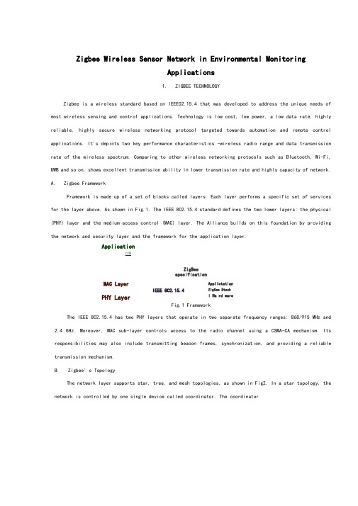
Zigbee Wireless Sensor Network in Environmental MonitoringApplications1. ZIGBEE TECHNOLOGYZigbee is a wireless standard based on IEEE02.15.4 that was developed to address the unique needs of most wireless sensing and control applications. Technology is low cost, low power, a low data rate, highly reliable, highly secure wireless networking protocol targeted towards automation and remote control applications. It's depicts two key performance characteristics -wireless radio range and data transmission rate of the wireless spectrum. Comparing to other wireless networking protocols such as Bluetooth, Wi-Fi, UWB and so on, shows excellent transmission ability in lower transmission rate and highly capacity of network.A. Zigbee FrameworkFramework is made up of a set of blocks called layers. Each layer performs a specific set of services for the layer above. As shown in Fig.1. The IEEE 802.15.4 standard defines the two lower layers: the physical (PHY) layer and the medium access control (MAC) layer. The Alliance builds on this foundation by providing the network and security layer and the framework for the application layer.Application口导ZigBeespecificationFig.1 FrameworkThe IEEE 802.15.4 has two PHY layers that operate in two separate frequency ranges: 868/915 MHz and2.4 GHz. Moreover, MAC sub-layer controls access to the radio channel using a CSMA-CA mechanism. Its responsibilities may also include transmitting beacon frames, synchronization, and providing a reliable transmission mechanism.B. Zigbee' s TopologyThe network layer supports star, tree, and mesh topologies, as shown in Fig2. In a star topology, the network is controlled by one single device called coordinator. The coordinatorMAC LayerIEEE 802.15.4PHY Layer Applictatian ZlgSee Stack I Ha rd wareis responsible for initiating and maintaining the devices on the network. All other devices, known as end devices, directly communicate with the coordinator. In mesh and tree topologies, the coordinator is responsible for starting the network and for choosing certainkey network parameters, but the network may be extended through the use of routers. In tree networks, routers move data and control messages through the network using a hierarchicalrouting strategy. Mesh networks allow full peer-to-peer communication.• Coordinator • Router (FFD| Fig.2 Mesh topologiesFig.3 is a network model, it shows that supports both single-hop star topology constructed with one coordinator in the center and the end devices, and mesh topology. In the network, the intelligent nodes are composed by Full Function Device (FFD) and Reduced Function Device (RFD). Only the FFN defines the full functionality and can become a network coordinator. Coordinator manages the network, it is to say thatcoordinator can start a network and allow other devices to join or leave it. Moreover, it can provide binding andaddress-table services, and save messages until they can be delivered.11. THE GREENHOUSE ENVIRONMENTAL MONITORINGSYSTEM DESIGNTraditional agriculture only use machinery and equipment which isolating and no communicating ability. And farmers have to monitor crops growth by th emselves. Even if some people use electrical devices, but most of them were restricted to simple communication between control computer and end devices like sensors instead X Star NetworkEnd Device i|RF 口)Mesh Network(Best RellabihtylTree Network (Least RAM) Z\n = H Coord in atariFFD.LlnHEnd 口・*lx|甘FEI nr< A »1)rFig.3 Zigbee network modelof wire connection, which couldn ' be strictly defined as wireless sensor network. Therefore, by through using sensor networks and, agriculture could become more automation, more networking and smarter.In this project, we should deploy five kinds of sensors in the greenhouse basement. By through these deployed sensors, the parameters such as temperature in the greenhouse, soil temperature, dew point, humidity and light intensity can be detected real time. It is key to collect different parameters from all kinds of sensors. And in the greenhouse, monitoring the vegetables growing conditions is the top issue. Therefore, longer battery life and lower data rate and less complexity are very important. From the introduction about above, we know that meet the requirements for reliability, security, low costs and low power.A.System OverviewThe overview of Greenhouseenvironmental monitoring system, which is made up by one sink node (coordinator), many sensor nodes, workstation and database. Mote node and sensor node together composed of each collecting node. When sensorscollect parameters real time, such as temperature in the greenhouse, soil temperature, dew point, humidity and light intensity, these data will be offered to A/D converter, then by through quantizing and encoding become the digital signal that is able to transmit by wireless sensor communicating node. Each wireless sensor communicating node has ability of transmitting, receiving function.In this WSN, sensor nodes deployed in the greenhouse, which can collect real time data and transmit data to sink node (Coordinator) by the way of multi-hop. Sink node complete the task of data analysis and data storage. Meanwhile, sink node is connected with GPRS/CDMA can provide remote control and data download service. In the monitoring and controlling room, by running greenhouse management software, the sink node can periodically receives the data from the wireless sensor nodes and displays them on monitors.B.Node Hardware DesignSensor nodes are the basic units of WSN. The hardware platform is made up sensor nodes closely related to the specific application requirements. Therefore, the most important work is the nodes design which can perfect implement the function of detecting and transmission as a WSN node, and perform its technology characteristics. Fig.4 shows the universal structure of the WSN nodes. Power module provides the necessary energy for the sensor nodes. Data collection module is used to receive and convert signals of sensors. Data processing and control module' sanctions are node device control, task scheduling, and energy computing and so on. Communication module is used to send data between nodes and frequency chosen and so on.Fig.4 Universal structure of the wsn nodesIn the data transfer unit, the module is embedded to match the MAC layer and the NET layer of the protocol. We choose CC 2430 as the protocol chips, which integrated the CPU, RF transceiver, net protocol and the RAM together. CC2430 uses an8 bit MCU ( 8051), and has 128KB programmable flash memory and 8KB RAM. It also includes A/D converter, some Timers, AES128 Coprocessor, Watchdog Timer,32K crystal Sleep mode Timer, Power on Reset, Brown out Detection and 21 I/Os. Based on the chips, many modules for the protocol are provided. And the transfer unit could be easily designed based on the modules.As an example of a sensor end device integrated temperature, humidity and light, the design is shown in Fig.5.Fig.5 The hardware design of a sensor nodeThe SHT11 is a single chip relative humidity and temperature multi sensor module comprising a calibrated digital output. It can test the soil temperature and humidity. The DS18B20 is a digital temperature sensor, which has 3 pins and data pin can link MSP 430 directly. It can detect temperature in greenhouse. The TCS320 is a digital light sensor. SHT11, DS18B20 and TCS320 are both digital sensors with small size and low power consumption. Other sensor nodes can be obtained by changing the sensors.The sensor nodes are powered from onboard batteries and the coordinator also allows to be powered from an external power supply determined by a jumper.C.Node Software DesignThe application system consists of a coordinator and several end devices. The general structure of the code in each is the same, with an initialization followed by a main loop.The software flow of coordinator, upon the coordinator being started, the first action of theapplication is the initialization of the hardware, liquid crystal, stack and application variables and opening the interrupt. Then a network will be formatted. If this net has been formatted successfully, some network information, such as physical address, net ID, channel number will be shown on the LCD. Then program will step into application layer and monitor signal. If there is end device or router want to join in this net, LCD will shown this information, and show the physical address of applying node, and the coordinatorwill allocate a net addressto this node. If the node has been joined in this network, the data transmitted by this node will be received by coordinator and shown in the LCD.The software flow of a sensor node, as each sensor node is switched on, it scans all channels and,after seeing any beacons, checks that the coordinator is the one that it is looking for. It then performs a synchronization and association. Once association is complete, the sensor node enters a regular loop of reading its sensors and putting out a frame containing the sensor data. If sending successfully, end device will step into idle state; by contrast, it will collect data once again and send to coordinator until sending successfully.D.Greenhouse Monitoring Software DesignWe use VB language to build an interface for the test and this greenhouse sensor network software can be installed and launched on any Windows-based operating system. It has 4 dialog box selections: setting controlling conditions, setting Timer, setting relevant parameters and showing current status. By setting some parameters, it can perform the functions of communicating with port, data collection and data viewing.Zigbee无线传感器网络在环境监测中的应用I. Zigbee技术Zigbee是一种基于IEEE802.15.4的无线标准上被开发用来满足大多数无线传感和控制应用的独特需求。
数据采集外文文献翻译中英文
数据采集外文文献翻译(含:英文原文及中文译文)文献出处:Txomin Nieva. DATA ACQUISITION SYSTEMS [J]. Computers in Industry, 2013, 4(2):215-237.英文原文DATA ACQUISITION SYSTEMSTxomin NievaData acquisition systems, as the name implies, are products and/or processes used to collect information to document or analyze some phenomenon. In the simplest form, a technician logging the temperature of an oven on a piece of paper is performing data acquisition. As technology has progressed, this type of process has been simplified and made more accurate, versatile, and reliable through electronic equipment. Equipment ranges from simple recorders to sophisticated computer systems. Data acquisition products serve as a focal point in a system, tying together a wide variety of products, such as sensors that indicate temperature, flow, level, or pressure. Some common data acquisition terms are shown below.Data collection technology has made great progress in the past 30 to 40 years. For example, 40 years ago, in a well-known college laboratory, the device used to track temperature rises in bronze made of helium was composed of thermocouples, relays, interrogators, a bundle of papers, anda pencil.Today's university students are likely to automatically process and analyze data on PCs. There are many ways you can choose to collect data. The choice of which method to use depends on many factors, including the complexity of the task, the speed and accuracy you need, the evidence you want, and more. Whether simple or complex, the data acquisition system can operate and play its role.The old way of using pencils and papers is still feasible for some situations, and it is cheap, easy to obtain, quick and easy to start. All you need is to capture multiple channels of digital information (DMM) and start recording data by hand.Unfortunately, this method is prone to errors, slower acquisition of data, and requires too much human analysis. In addition, it can only collect data in a single channel; but when you use a multi-channel DMM, the system will soon become very bulky and clumsy. Accuracy depends on the level of the writer, and you may need to scale it yourself. For example, if the DMM is not equipped with a sensor that handles temperature, the old one needs to start looking for a proportion. Given these limitations, it is an acceptable method only if you need to implement a rapid experiment.Modern versions of the strip chart recorder allow you to retrieve data from multiple inputs. They provide long-term paper records of databecause the data is in graphic format and they are easy to collect data on site. Once a bar chart recorder has been set up, most recorders have enough internal intelligence to operate without an operator or computer. The disadvantages are the lack of flexibility and the relative low precision, often limited to a percentage point. You can clearly feel that there is only a small change with the pen. In the long-term monitoring of the multi-channel, the recorders can play a very good role, in addition, their value is limited. For example, they cannot interact with other devices. Other concerns are the maintenance of pens and paper, the supply of paper and the storage of data. The most important is the abuse and waste of paper. However, recorders are fairly easy to set up and operate, providing a permanent record of data for quick and easy analysis.Some benchtop DMMs offer selectable scanning capabilities. The back of the instrument has a slot to receive a scanner card that can be multiplexed for more inputs, typically 8 to 10 channels of mux. This is inherently limited in the front panel of the instrument. Its flexibility is also limited because it cannot exceed the number of available channels. External PCs usually handle data acquisition and analysis.The PC plug-in card is a single-board measurement system that uses the ISA or PCI bus to expand the slot in the PC. They often have a reading rate of up to 1000 per second. 8 to 16 channels are common, and the collected data is stored directly in the computer and then analyzed.Because the card is essentially a part of the computer, it is easy to establish the test. PC-cards are also relatively inexpensive, partly because they have since been hosted by PCs to provide energy, mechanical accessories, and user interfaces. Data collection optionsOn the downside, the PC plug-in cards often have a 12-word capacity, so you can't detect small changes in the input signal. In addition, the electronic environment within the PC is often susceptible to noise, high clock rates, and bus noise. The electronic contacts limit the accuracy of the PC card. These plug-in cards also measure a range of voltages. To measure other input signals, such as voltage, temperature, and resistance, you may need some external signal monitoring devices. Other considerations include complex calibrations and overall system costs, especially if you need to purchase additional signal monitoring devices or adapt the PC card to the card. Take this into account. If your needs change within the capabilities and limitations of the card, the PC plug-in card provides an attractive method for data collection.Data electronic recorders are typical stand-alone instruments that, once equipped with them, enable the measurement, recording, and display of data without the involvement of an operator or computer. They can handle multiple signal inputs, sometimes up to 120 channels. Accuracy rivals unrivalled desktop DMMs because it operates within a 22 word, 0.004 percent accuracy range. Some data electronic automatic recordershave the ability to measure proportionally, the inspection result is not limited by the user's definition, and the output is a control signal.One of the advantages of using data electronic loggers is their internal monitoring signals. Most can directly measure several different input signals without the need for additional signal monitoring devices. One channel can monitor thermocouples, RTDs, and voltages.Thermocouples provide valuable compensation for accurate temperature measurements. They are typically equipped with multi-channel cards. Built-in intelligent electronic data recorder helps you set the measurement period and specify the parameters for each channel. Once you set it all up, the data electronic recorder will behave like an unbeatable device. The data they store is distributed in memory and can hold 500,000 or more readings.Connecting to a PC makes it easy to transfer data to a computer for further analysis. Most data electronic recorders can be designed to be flexible and simple to configure and operate, and most provide remote location operation options via battery packs or other methods. Thanks to the A/D conversion technology, certain data electronic recorders have a lower reading rate, especially when compared with PC plug-in cards. However, a reading rate of 250 per second is relatively rare. Keep in mind that many of the phenomena that are being measured are physical in nature, such as temperature, pressure, and flow, and there are generallyfewer changes. In addition, because of the monitoring accuracy of the data electron loggers, a large amount of average reading is not necessary, just as they are often stuck on PC plug-in cards.Front-end data acquisition is often done as a module and is typically connected to a PC or controller. They are used in automated tests to collect data, control and cycle detection signals for other test equipment. Send signal test equipment spare parts. The efficiency of the front-end operation is very high, and can match the speed and accuracy with the best stand-alone instrument. Front-end data acquisition works in many models, including VXI versions such as the Agilent E1419A multi-function measurement and VXI control model, as well as a proprietary card elevator. Although the cost of front-end units has been reduced, these systems can be very expensive unless you need to provide high levels of operation, and finding their prices is prohibited. On the other hand, they do provide considerable flexibility and measurement capabilities.Good, low-cost electronic data loggers have the right number of channels (20-60 channels) and scan rates are relatively low but are common enough for most engineers. Some of the key applications include:•product features•Hot die cutting of electronic products•Test of the environmentEnvironmental monitoring•Composition characteristics•Battery testBuilding and computer capacity monitoringA new system designThe conceptual model of a universal system can be applied to the analysis phase of a specific system to better understand the problem and to specify the best solution more easily based on the specific requirements of a particular system. The conceptual model of a universal system can also be used as a starting point for designing a specific system. Therefore, using a general-purpose conceptual model will save time and reduce the cost of specific system development. To test this hypothesis, we developed DAS for railway equipment based on our generic DAS concept model. In this section, we summarize the main results and conclusions of this DAS development.We analyzed the device model package. The result of this analysis is a partial conceptual model of a system consisting of a three-tier device model. We analyzed the equipment project package in the equipment environment. Based on this analysis, we have listed a three-level item hierarchy in the conceptual model of the system. Equipment projects are specialized for individual equipment projects.We analyzed the equipment model monitoring standard package in the equipment context. One of the requirements of this system is the ability to use a predefined set of data to record specific status monitoring reports. We analyzed the equipment project monitoring standard package in the equipment environment. The requirements of the system are: (i) the ability to record condition monitoring reports and event monitoring reports corresponding to the items, which can be triggered by time triggering conditions or event triggering conditions; (ii) the definition of private and public monitoring standards; (iii) Ability to define custom and predefined train data sets. Therefore, we have introduced the "monitoring standards for equipment projects", "public standards", "special standards", "equipment monitoring standards", "equipment condition monitoring standards", "equipment project status monitoring standards and equipment project event monitoring standards, respectively Training item triggering conditions, training item time triggering conditions and training item event triggering conditions are device equipment trigger conditions, equipment item time trigger conditions and device project event trigger condition specialization; and training item data sets, training custom data Sets and trains predefined data sets, which are device project data sets, custom data sets, and specialized sets of predefined data sets.Finally, we analyzed the observations and monitoring reports in the equipment environment. The system's requirement is to recordmeasurements and category observations. In addition, status and incident monitoring reports can be recorded. Therefore, we introduce the concept of observation, measurement, classification observation and monitoring report into the conceptual model of the system.Our generic DAS concept model plays an important role in the design of DAS equipment. We use this model to better organize the data that will be used by system components. Conceptual models also make it easier to design certain components in the system. Therefore, we have an implementation in which a large number of design classes represent the concepts specified in our generic DAS conceptual model. Through an industrial example, the development of this particular DAS demonstrates the usefulness of a generic system conceptual model for developing a particular system.中文译文数据采集系统Txomin Nieva数据采集系统, 正如名字所暗示的, 是一种用来采集信息成文件或分析一些现象的产品或过程。
无线射频识别技术外文翻译参考文献
无线射频识别技术外文翻译参考文献无线射频识别技术外文翻译参考文献(文档含中英文对照即英文原文和中文翻译)翻译:当前无线射频识别技术应用略述摘要无线射频识别技术可以自动识别多目标并以非接触式方式移动目标。
越来越多的零售商、银行、交通管理系统、展览及物流供应商将这项新技术应用于他们的产品和服务。
因此,这给RFID技术的研究带来了机遇和挑战。
本文简单介绍了RFID系统的组成、原理及RFID技术的特点。
本文比较了RFID 与传统条码,然后提供了一个简短的关于目前RFID 应用情况的调查报告。
关键词:无线射频识别技术应用物流一、简介无线射频识别(RFID )是一种识别技术。
与RFID 技术的前身——条码技术相比,RFID 技术具有很多的优点。
但由于其成本高,RFID 技术至今未能广泛应用到各行各业。
RFID 技术因其无需视线扫描而具有无可比拟的先进性,它能够降低劳动力水平,提高知名度并改善库存管理。
RFID 技术的普及提供了一项人或物体定位及追踪的解决方案。
RFID 定位与跟踪系统根据独特的识别标签、阅读器与物体标签间射频通信的信号强度确定物体的空间位置,主要适用于室内,而GPS 系统是不适合应用于室内的。
RFID 技术是一项基于“无线电频率”的非接触式的自动识别技术,自动识别静态或动态的人和对象。
RFID 标签是一个特殊的微芯片,植入商品中,可以跟踪和管理物理对象,是物流管理信息化和跟踪信息化的重要手段。
RFID 的系统组成部分包括:(1)标签(应答器):对象植入待确定。
(2)阅读器:可以读或读/写,按结构和技术。
正如图1-1,RFID 的工作原理图1-1 RFID 的工作原理与计算机通讯阅读器电磁波(操作指令和新的数据)标签发出的ID代码和数据二、目前RFID技术的研究重点由于RFID技术日趋成熟且RFID标签价格下降,RFID越来越受到工业界和学术界的关注。
通过在物品上贴射频标签,我们就可以跟踪和管理这些对象。
数据采集外文翻译
中文1950字附录附录A外文资料Data CollectionAt present,the management of China’s colleges and universities’apartments are developing toward standardization and market development,accidents have occurred in electricity,while some colleges and universities have installed apart ment energy metering control system,however,these systems monitor the prevale nce of low level,billing accuracy is low,electricity-sharing,the network number o f the drawbacks of low extent.Therefore,improving the Energy Measurement m onitoring device has become more urgent.The issue of student hostels in colle ges and universities to monitor energy metering system to study,design the st udent hostels in colleges and universities of the electricity data collector apartm ent.Data acquisition, also known as data acquisition, is the use of a device th at collect data from outside the system and enter into an interface within the s ystem.Data acquisition technology is widely cited in the various fields.Such as camera, microphone, all data collection tools.Data is being collected has been c onverted to electrical signals of various physical quantities such as temperature, water level, wind speed, pressure, etc., can be analog, it can be digital.Sampl e collection generally means that a certain time interval (called the sampling p eriod) to repeat the same point of data collection.The data collected are mostly instantaneous value, but also a feature within a certain period of time value.A ccurate data measurement is the basis for data collection.Data measurement met hod of contact and non-contact detection elements varied.Regardless of which method and components are measured object does not affect the status and me asurement environment as a precondition to ensure the accuracy of the data.Ver y broad meaning of data collection, including continuous physical hold the collection across the state.In computer-aided mapping, surveying and mapping, desi gn, digital graphics or image data acquisition process may also be called, this time to be collected is the geometric volume (or include physical quantities, su ch as gray)data.[1] In today's fast-growing Internet industry, data collection has been widely used in the field of Internet and distributed data acquisition field has undergone important changes.First, the distributed control applications in i ntelligent data acquisition system at home and abroad have made great progres s.Second, the bus-compatible data acquisition plug-in number is increasing, and personal computer-compatible data acquisition system the number is increasing. Various domestic and international data collection machine has come out, the d ata acquisition into a new era.Digital signal processor (DSP) to the high-speed data processing ability an d strong peripherals interface, more and more widely used in power quality an alysis field, in order to improve the real-time and reliability.The DSP and micr ocomputer as the center of the system, realize the power system signal collecti on and analysis. This paper based on the FFT algorithm with window interpola tion electric system harmonic analysis, improves the accuracy of the power qua lity parameters. In electricity parameter acquisition circuit, by highaccuracy tran sformer and improve software synchronous communication sampling method to conduct electricity parameters of the acquisition.The system consists of two main components, mainly complete data acquis ition and logic control.To synchronous sampling and A/D converter circuit pri ority . The DSP development board(SY-5402EVM),complete data processing. T HE signal after transformer, op-amp into A/D converter, using DSP multi-chann el buffer (McBSP) and serial port (A/D connected, data collection and operatio ns. At the same time, adopt PLL circuit implementation synchronous sampling, can prevent well due to sampling synchronization and cause the measuring err or. The overall system diagram of the A/D converter chooses the Analog to pr oduce stats redetect (AD) company AD73360. The chip has six analogue input channel, each channel can output 16 the digital quantity. Six channel simultan eous sampling, and conversion, timeshare transmission, effectively reduce gener ated due to the sampling time different phase error. SY - 5402EVM on-board DSP chip is TI company's 16 fixed-point digital signal processor TMS320VC54 02. It has high costperformance and provide high-speed, bidirectional, multi-channel belt cushion, be used to serial port with system of other serial devices di rectly interface.The realization method of ac sample:In the field of power quality analysi s,The fast Fourier transform (FFT) algorithm analysis of electric system harmon ic is commonly used.and the FFT algorithm to signal a strict requirements syn chronous sampling. The synchronous sampling influence: it's difficult to accomp lish synchronous sampling and integer a period truncation in the actual measur ement, so there was a affect the measurement accuracy of the frequency spectr um leakage problem. The signal has to deal with through sampling and A/D c onversion get limited long digital sequence,the original signal multiplied by A r ectangular window to truncated. Time-domain truncation will cause the detuning frequency domain, spectrum leakage occurs. In the synchronous sampling, bec ause the actual signal every harmonic component can't exactly landed in freque ncy resolution point in, but fall between the frequency resolution points. But F FT spectrum is discrete, only in all sampling points, while in other places of s pectrum is not. Such through FFT and cannot directly get every harmonic com ponent, but only the accurate value in neighboring frequency resolution point v alue to approximate instead of, can cause the fence effect error.The realization method of synchronous sampling signal:According to provide different ways of sampling signal, synchronous sampling method and divided into software sync hronous sampling method and hardware synchronous sampling method is two k inds. Software is synchronous sampling method by micro controller (MCU) or DSP provide synchronized sampling pulse, first measured the measured signal, the sa mpling interval period T Δ T = T/N (N for week of sampling points), T hus the count value determined timer,Use timing interrupt way realization sync hronous sampling. The advantage of this method is no hardware synchronous c ircuit, simple structure .This topic will be the eventual realization of access to embedded systems,the realization of the power measurement and monitoring,m onitoring system to meet the electricity network,intelligence requirement,it prom ote the development of remote monitoring services,bringing a certain degree of socio.economic effectiveness.On the fundamental reactive current and harmonic current detection, there are mainly 2 ways: First, the instantaneous reactive power theory based method, the second is based on adaptive cancellation techniques.In addition, there areother non-mainstream approach, such as fast Fourier transform method, wavelet transform.Instantaneous power theory based on the method of offensive principles ar e: a three-phase current detection and load phase voltage A, the coordinate tra nsformation, two-phase stationary coordinate system the current value, calculate the instantaneous active and instantaneous reactive power ip iq,then after coor dinate transformation, three-phase fundamental active current, with the final loa d current minus the fundamental current, active power and harmonic currents a re fundamental iah, ibhi, ich.From:Principles of Data Acquisitio数据采集目前,我国高校公寓管理正在向着正规化、市场化发展,在不断提高学生方便用电的同时,用电事故频有发生,虽然部分高校公寓已经安装了电能计量监控系统,但这些系统普遍存在着监控程度低、计费精度不高、电费均分、网络程度低等诸多端。
蜂窝无线通信系统中英文对照外文翻译文献
中英文对照外文翻译文献(文档含英文原文和中文翻译)原文:RESEARCH OF CELLULAR WIRELESS COMMUNATIONSYSTEMA wide variety of wireless communication systems have been developed to provide access to the communications infrastructure for mobile or fixed users in a myriad of operating environments. Most of today’s wireless systems are based on the cellular radio concept. Cellular communication systems allow a large number of mobile users to seamlessly and simultaneously communicate to wireless modems at fixed base stations using a limited amount of radio frequency (RF) spectrum. The RF transmissions received at the base stations from each mobile are translated to baseband, or to a wideband microwave link, and relayed to mobile switching centers (MSC), which connect the mobile transmissions with the Public Switched Telephone Network (PSTN). Similarly, communications from the PSTN are sent to the base station, where they are transmitted to the mobile. Cellular systems employ eitherfrequency division multiple access (FDMA), time division multiple access (TDMA), code division multiple access (CDMA), or spatial division multiple access (SDMA) .Wireless communication links experience hostile physical channel characteristics, such as time-varying multipath and shadowing due to large objects in the propagation path. In addition, the performance of wireless cellular systems tends to be limited by interference from other users, and for that reason, it is important to have accurate techniques for modeling interference. These complex channel conditions are difficult to describe with a simple analytical model, although several models do provide analytical tractability with reasonable agreement to measured channel data . However, even when the channel is modeled in an analytically elegant manner, in the vast majority of situations it is still difficult or impossible to construct analytical solutions for link performance when error control coding, equalization, diversity, and network models are factored into the link model. Simulation approaches, therefore, are usually required when analyzing the performance of cellular communication links.Like wireless links, the system performance of a cellular radio system is most effectively modeled using simulation, due to the difficulty in modeling a large number of random events over time and space. These random events, such as the location of users, the number of simultaneous users in the system, the propagation conditions, interference and power level settings of each user, and the traffic demands of each user, combine together to impact the overall performance seen by a typical user in the cellular system. The aforementioned variables are just a small sampling of the many key physical mechanisms that dictate the instantaneous performance of a particular user at any time within the system. The term cellular radio system, therefore, refers to the entire population of mobile users and base stations throughout the geographic service area, as opposed to a single link that connects a single mobile user to a single base station. To design for a particular system-level performance, such as the likelihood of a particular user having acceptable service throughout the system, it is necessary to consider the complexity of multiple users that are simultaneously using the system throughout the coverage area. Thus, simulation is needed to consider the multi-user effects upon any of the individual links between the mobile and the base station.The link performance is a small-scale phenomenon, which deals with the instantaneouschanges in the channel over a small local area, or small time duration, over which the average received power is assumed constant. Such assumptions are sensible in the design of error control codes, equalizers, and other components that serve to mitigate the transient effects created by the channel. However, in order to determine the overall system performance of a large number of users spread over a wide geographic area, it is necessary to incorporate large-scale effects such as the statistical behavior of interference and signal levels experienced by individual users over large distances, while ignoring the transient channel characteristics. One may think of link-level simulation as being a vernier adjustment on the performance of a communication system, and the system-level simulation as being a coarse, yet important, approximation of the overall level of quality that any user could expect at any time.Cellular systems achieve high capacity (e.g., serve a large number of users) by allowing the mobile stations to share, or reuse a communication channel in different regions of the geographic service area. Channel reuse leads to co-channel interference among users sharing the same channel, which is recognized as one of the major limiting factors of performance and capacity of a cellular system. An appropriate understanding of the effects of co-channel interference on the capacity and performance is therefore required when deploying cellular systems, or when analyzing and designing system methodologies that mitigate the undesired effects of co-channel interference. These effects are strongly dependent on system aspects of the communication system, such as the number of users sharing the channel and their locations. Other aspects, more related to the propagation channel, such as path loss, shadow fading (or shadowing), and antenna radiation patterns are also important in the context of system performance, since these effects also vary with the locations of particular users. In this chapter, we will discuss the application of system-level simulation in the analysis of the performance of a cellular communication system under the effects of co-channel interference. We will analyze a simple multiple-user cellular system, including the antenna and propagation effects of a typical system. Despite the simplicity of the example system considered in this chapter, the analysis presented can easily be extended to include other features of a cellular system.2 Cellular Radio SystemSystem-Level Description:Cellular systems provide wireless coverage over a geographic service area by dividing the geographic area into segments called cells as shown in Figure 2-1. The available frequency spectrum is also divided into a number of channels with a group of channels assigned to each cell. Base stations located in each cell are equipped with wireless modems that can communicate with mobile users. Radio frequency channels used in the transmission direction from the base station to the mobile are referred to as forward channels, while channels used in the direction from the mobile to the base station are referred to as reverse channels. The forward and reverse channels together identify a duplex cellular channel. When frequency division duplex (FDD) is used, the forward and reverse channels are split in frequency. Alternatively, when time division duplex (TDD) is used, the forward and reverse channels are on the same frequency, but use different time slots for transmission.Figure 2-1 Basic architecture of a cellular communications system High-capacity cellular systems employ frequency reuse among cells. This requires that co-channel cells (cells sharing the same frequency) are sufficiently far apart from each other to mitigate co-channel interference. Channel reuse is implemented by covering the geographic service area with clusters of N cells, as shown in Figure 2-2, where N is known as the cluster size.Figure 2-2 Cell clustering:Depiction of a three-cell reuse pattern The RF spectrum available for the geographic service area is assigned to each cluster, such that cells within a cluster do not share any channel . If M channels make up the entire spectrum available for the service area, and if the distribution of users is uniform over the service area, then each cell is assigned M/N channels. As the clusters are replicated over the service area, the reuse of channels leads to tiers of co-channel cells, and co-channel interference will result from the propagation of RF energy between co-channel base stations and mobile users. Co-channel interference in a cellular system occurs when, for example, a mobile simultaneously receives signals from the base station in its own cell, as well as from co-channel base stations in nearby cells from adjacent tiers. In this instance, one co-channel forward link (base station to mobile transmission) is the desired signal, and the other co-channel signals received by the mobile form the total co-channel interference at the receiver. The power level of the co-channel interference is closely related to the separation distances among co-channel cells. If we model the cells with a hexagonal shape, as in Figure 2-2, the minimum distance between the center of two co-channel cells, called the reuse distance ND, is(2-1)R3D N Nwhere R is the maximum radius of the cell (the hexagon is inscribed within the radius).Therefore, we can immediately see from Figure 2-2 that a small cluster size (small reuse distance ND), leads to high interference among co-channel cells.The level of co-channel interference received within a given cell is also dependent on the number of active co-channel cells at any instant of time. As mentioned before, co-channel cells are grouped into tiers with respect to a particular cell of interest. The number of co-channel cells in a given tier depends on the tier order and the geometry adopted to represent the shape of a cell (e.g., the coverage area of an individual base station). For the classic hexagonal shape, the closest co-channel cells are located in the first tier and there are six co-channel cells. The second tier consists of 12 co-channel cells, the third, 18, and so on. The total co-channel interference is, therefore, the sum of the co-channel interference signals transmitted from all co-channel cells of all tiers. However, co-channel cells belonging to the first tier have a stronger influence on the total interference, since they are closer to the cell where the interference is measured.Co-channel interference is recognized as one of the major factors that limits the capacity and link quality of a wireless communications system and plays an important role in the tradeoff between system capacity (large-scale system issue) and link quality (small-scale issue). For example, one approach for achieving high capacity (large number of users), without increasing the bandwidth of the RF spectrum allocated to the system, is to reduce the channel reuse distance by reducing the cluster size N of a cellular system . However, reduction in the cluster sizeincreases co-channel interference, which degrades the link quality.The level of interference within a cellular system at any time is random and must be simulated by modeling both the RF propagation environment between cells and the position location of the mobile users. In addition, the traffic statistics of each user and the type of channel allocation scheme at the base stations determine the instantaneous interference level and the capacity of the system.The effects of co-channel interference can be estimated by the signal-tointerference ratio (SIR) of the communication link, defined as the ratio of the power of the desired signal S, to the power of the total interference signal, I. Since both power levels S and I are random variables due to RF propagation effects, user mobility and traffic variation, the SIR is also a random variable. Consequently, the severity of the effects of co-channel interference onsystem performance is frequently analyzed in terms of the system outage probability, defined in this particular case as the probability that SIR is below a given threshold 0S IR . This isdx p ]SIR Pr[SIR P )x 0SIR 0SIR 0outpage (⎰=<= (2-2)Where is the probability density function (pdf) of the SIR. Note the distinction between the definition of a link outage probability, that classifies an outage based on a particular bit error rate (BER) or Eb/N0 threshold for acceptable voice performance, and the system outage probability that considers a particular SIR threshold for acceptable mobile performance of a typical user.Analytical approaches for estimating the outage probability in a cellular system, as discussed in before, require tractable models for the RF propagation effects, user mobility, and traffic variation, in order to obtain an expression for PSIR (x ). Unfortunately, it is very difficult to use analytical models for these effects, due to their complex relationship to the received signal level. Therefore, the estimation of the outage probability in a cellular system usually relies on simulation, which offers flexibility in the analysis. In this chapter, we present a simple example of a simulation of a cellular communication system, with the emphasis on the system aspects of the communication system, including multi-user performance, traffic engineering, and channel reuse. In order to conduct a system-level simulation, a number of aspects of the individual communication links must be considered. These include the channel model, the antenna radiation pattern, and the relationship between Eb/N0 (e.g., the SIR) and the acceptable performance.SIR(x)p翻译:蜂窝无线通信系统的研究摘要蜂窝通信系统允许大量移动用户无缝地、同时地利用有限的射频(radio frequency,RF)频谱与固定基站中的无线调制解调器通信。
- 1、下载文档前请自行甄别文档内容的完整性,平台不提供额外的编辑、内容补充、找答案等附加服务。
- 2、"仅部分预览"的文档,不可在线预览部分如存在完整性等问题,可反馈申请退款(可完整预览的文档不适用该条件!)。
- 3、如文档侵犯您的权益,请联系客服反馈,我们会尽快为您处理(人工客服工作时间:9:00-18:30)。
无线数据采集和传输系统外文翻译文献(文档含中英文对照即英文原文和中文翻译)译文:一种无线数据采集和传输系统的设计【摘要】在现代无线通信领域主要有一些技术为无线传输网络提供解决方法,例如:GSM,CDMA,3G,Wi-Fi。
这些方法使得网络能够高效率和高质量的工作,但是成本很高。
因此要低成本和在没有基础设施或者基础设施被破坏的情况下推广它们是很困难的。
根据这种情况,本论文中数据采集和无线传输网络里的信息终端和无线收发模块的关键部件,是依据nRF905收发模块和51系列单片机的原理设计而成作为核心硬件,此外,结合目前自组无线网络的技术,可以构建一个短距离无线数据采集和传输网络,这个网络能够提供一个工作在ISM(工业科学医学)频段的低功率及高性能的数据通信系统。
然后提出了一个对无线通信可行的解决方案,这个方案优势在于更强的实时响应,更高的可靠性要求和更小的数据量。
通过软件和硬件的调试和实际测量,这个系统在我们的解决方案基础上运行良好,达到了预期的目标并且已经成功的应用到无线车辆系统。
【关键词】自组网络;数据采集;传输网络1 简介在现代无线通信里,GSM,CDMA,3G和Wi-Fi因为其高速和可靠的质量而逐渐成为无线数据传输网络的主流解决方案。
它们也有高成本的缺点,因此如果广泛的应用,将会引起大量的资源浪费,也不能在小区域,低速率的数据通信中得到提升。
多点短距离无线数据采集和传输网络将成为最佳解决方案。
此系统支持点对点,点对多点和多点对多点通信系统的发展。
短距离无线通信可以适应各种不同的网络技术,例如蓝牙,IEEE802.11,家庭无线网和红外。
与远距离无线通信网络相比,它们的不同之处在于基本结构,应用水平,服务范围和业务(数据,语音)。
设计短距离无线通信网络的最初目的是为了提供短距离宽带无线接入到移动环境或者制定临时网络,这是在移动环境里互联网更深的发展。
短距离无线通信网络最主要的优势是更低的成本和更灵活的应用。
本文介绍信息终端(单个器件)的硬件和软件以及多点短距离无线数据采集和传输网络的无线接收模块的设计建议,提供一个低功率高性能的工作于ISM(工业科学医学)频段的无线数据通信系统。
文章剩余部分由如下内容组成:在第二部分,我们描述了无线数据采集和传输系统的通用模块图表,第三部分,我们分析此系统硬件设计的关键技术,第四部分,介绍系统的软件设计,第五部分,展示系统的测试结果,最后我们在第六部分阐述结论和进一步的工作。
2 系统实现模型1.系统模型作为一个点对多点的多功能无线通信系统,它包含了一个中央监控系统和多个远程终端单元(图1)。
实际上,远程终端单元是一些在移动过程中可互相通信的移动电台。
另外,中央监控系统与远程终端单元进行双向通信。
在下一部分,设计信息终端和控制中心的软件和硬件上的一些关键部件。
2.相关模型本论文中的系统是根据OSI(国际标准组织)中的OSI/RM模型里的第一层(物理层)和第二层(数据链路层)而设计的,如图2所示。
物理层的功能是通过建立电路和专用芯片组完成的。
然而通信协议里的数据链路层是由软件来实现的。
3 系统硬件设计为了设计,管理和更新的方便,一些硬件单元和节点根据它们的功能和电学特性被划分成不同的模型。
本设计以射频收发芯片nRF905为核心,以模块搭建设计为指导思想,搭建无线温度采集系统,系统主要由数据采集模块和无线传输模块组成。
数据采集模块以数字式温度传感器DSl8B20监测温度参数,并将监测的温度参数简单处理后通过nRF905无线模块发送到接收端口。
无线数据传输模块通过nRF905芯片进行数据收发处理,nRF905芯片的集成度较高,所需的外围器件较少,因此整体的电路设计相对比较简单点。
本设计给出其与MSP430F449的接口电路设计和接收端通过电平转换芯片MAX3232与PC机连接。
并根据硬件特性及连接设计相应的软件流程,并编写软件。
通过相适应的无线传输模块和数据采集模块控制软件的操控,保证整个硬件系统的流畅运作。
系统基本结构中包含无线射频收发模块,控制处理模块,通用串行接口模块,数据缓冲存储模块以及多功能电源管理模块等。
1.收发器和接收模块在数据发送过程中,数据包将被调制到高频然后发送到目标无线射频传输模块,接收过程中,高频信号通过无线射频接收模块又被解调成原始数据包。
NRF905是无线射频收发模块的关键,它的频率是16兆赫兹的晶体振荡器。
NRF905可以通过印刷式天线接收无线射频信号,但是为了提高接收机的灵敏度和抗干扰能力,这种模块也适用外部天线和滤波器电路。
2.控制处理模块控制处理模块包含MCU和外部电路,有两个功能:一是使所有模块在其控制下协调工作,二是处理和传输从接口来的数据,例如路由处理,数据打包,验证和重传请求。
模块的关键部件MCU是51系列单片机,考虑到工业功能,WINBOND 78LE546因其在8位CMOS微处理器里较好的容量特性被而被应用,与2.4-2.5伏的宽电压供电,256比特嵌入式RAM,16KB Flash EPROM以及64KB地址空间,四个8位标准I/O接口,一个标准I/O双串行口相兼容。
SCM的晶体振荡器频率是22.1184兆赫兹,电功率为3.3伏适合无线收发芯片里nRF905的逻辑水平。
它的引脚通过与VCC相连受到保护并保持器稳定性。
MCU与所有模块的具体连接如表1所示。
4 系统软件设计系统性能的真实取决于其有效性和合理的软件控制。
软件设计是在硬件环境的基础上开发一个无线网络协议,为了到达设计目标,这个协议要有诸如数据传输,冲突避免,错误后重传以及超时重试的功能。
整个网络由一个主机和许多分散的终端组成,每个终端必须有一个无线收发节点(此系统支持Nrf905单片无线收发器),整个无线网络的任何节点都有一个唯一认证地址对应一个唯一认证终端。
为了方便起见,每个确定系统的终端无线收发器节点地址都是我们自己设定的4字节。
为了提高系统的稳定性,协议被设置成停止-等待模式。
在数据链路层,发送过程大概如下:首先,数据源发送一个连接请求道数据目标,得到数据源的响应后传输数据。
接着,每一次传输都要等待接收方的回应。
如果响应正确,另一次的传输才会开始。
当所有数据传输完后,数据源将发送一个释放信道请求,当收到接收方的响应后传输结束。
接收过程如下:在接收方给数据源响应后将收到数据,然后会发送一个有效或无效的响应,直到收到拆除链路请求。
接下来,保存数据且发送一个响应来结束整个过程。
5 系统测试任何两个节点之间的通信大都可以通过点对点来测试,因此在系统测试过程中,A节点和B节点之间的通信模型对测试图解来说是一个很好的样本,就像图10。
闭环测试电路是通过PC带双串口以及两个RS32口和通信节点A和B建立起来的。
在一个终端,数据时通过串口测试辅助工具“串口助手V2.2”发送,在另一端,监控着返回的数据。
数据通过PC的串口A,RS32口发送,然后数据缓冲,最后成功到达终端无线收发器模块。
然而,数据接收过程是SPI串口,数据缓冲,然后RS32口,最后才是PC。
在本论文中,根据以收发器nRF905和51系列单片机作为核心硬件的原理设计一个低功耗高性能的无线数据通信系统。
提出无线数据通信一个可行的解决方案,这个解决方案适合于强大的实时响应,高可靠性要求和小数据量,被广泛的应用于各种领域,例如数据通信,环境监测和安全保卫系统。
我们相信在软件设计进一步精炼和提高以后集成和智能通信协议将会实现。
测试过程中,用数字示波器监测通信节点A、B,RS32口和SPI口的数据传输。
在接下来的部分,通过分析来自MOSI/SCK和MISO/SCK 的信息来验证系统的正确性。
6 总结在本论文中,根据以收发器nRF905和51系列单片机作为核心硬件的原理设计一个低功耗高性能的无线数据通信系统。
提出无线数据通信一个可行的解决方案,这个解决方案适合于强大的实时响应,高可靠性要求和小数据量,被广泛的应用于各种领域,例如数据通信,环境监测和安全保卫系统。
我们相信在软件设计进一步精炼和提高以后集成和智能通信协议将会实现。
原文:The Design of a Wireless Data Acquisitionand Transmission SystemAbstract—In the field of modern wireless communication, there are mainly some technologies that provide solutions to the wireless data transmission network, such as: GSM, CDMA, 3G, Wi-Fi.These solutions make network work with high efficiency and good quality, but still with high cost. So it was difficulty in popularizing in with low cost and at the circumstance of infrastureless or infrastructure destruction. According to this situation, in this paper, the key components of the Information Terminal and the wireless receiving modules on the data collection and wireless transmission network were designed with the principle of transceiver nRF905 and 51 series of single-chip computer as the core hardware, besides, combining with the current technology on the Wireless Ad Hoc Networks,a short-rang wireless data sampling and transmission network was putting up,which provides a low-powered and high-performance wireless data communication system, works in the ISM (Industrial Scientific Medical )Band.Then,an available solution to the wireless data communications was put forward, and this solution was good at stronger real-time response, higher reliability requirement and smaller data amount. Through software and hardware debugging and actual measuring, this system based on our solution had work well, reached the expected goal and been already successfully applied toWireless vehicle System.Index Terms—Ad Hoc Network;data acquisition; transmission network.I. INTRODUCTIONIn modern wireless communication,GSM,CDMA, 3G, and Wi-Fi become the mainstream solution of wireless data transmission network because of their high speed and reliable quality. They also have the shortcomings of high cost, so wider application would cause a great waste of resources, and they cannot be promoted in small regional, low speed data communications.Multi-point short-range wireless data collection and transmission network will be the best solution.The system supports the development of communication system of peer-to-peer, point-to-multipoint, and multipoint-to-multipoint. Short-range wireless communication can adopt different network technologies, such as Bluetooth [1], IEEE802.11 [2],HomeRF [3] and Infrared [4]. Compared with long-distance wireless communication network, they are different in the basic structure, the application level, service range, and business (data, voice). The originalintention of design of short-range wireless communication network is to provide short-distance broadband wireless access to mobile environment or formulation of temporary network, it is the further development of internet in mobile environment. The main advantage of short-range wireless communication network is lower cost and more flexible use. This paper presents the design proposal of hardware and software of information terminal (a machine) and wireless receiver module of multi-point short-range wirelessdata collection and transmission network, which provides a low-powered and high-performance wireless data communication system, works in the ISM (Industrial Scientific Medical)Band. The remainder of this paper is organized as follows. In Section Ⅱ, we describe the general block diagram of the wireless data acquisition and transmission system. In section Ⅲ, we analyze the key technologies about the system hardware design. In section Ⅳ, the system software design is introduced. In section Ⅴ, the testing results of system is presented. Finally, we present the conclusion and future work in Section Ⅵ.II. SYSTEM IMPLEMENTATION MODELA. System ModelAs a point to multi-points multi-mission wireless communication system, it consists of one central monitoring system (CMS) and Multiple Remote Terminal Units (RTU) (figure 1). In fact, this remote terminal unit is some kind of removable stations which can communicate with other stations in the process of motion. Furthermore, the CMS communicate with RTU in bidirectional way. In the next part, some pivotal segment on software and hardware of the information terminal and control center was designed.B. Reference ModelThe system in this paper is designed based on the first layer (the physical layer) and the second layer (the data link layer) of the architecture of OSI/RM (Open Systems Interconnection Reference Model) that the ISO (InternationalOrganization for Standardization) proposed, such as figure 2. The function of the physical layer is finished through constructing the circuit and special chips. Otherwise, communication protocols in the data link layer are realized by software.Ⅲ.THE HARDWARE DESIGN OF THE SYSTEMFor the sake of the convenience of design, maintenance and update, some hardware circuit cell and node was divided into some different module according to functional and electric characteristic. There are RF Transceiver module [5], controlling and dealing module, Universal Serial interface module, data buffer and storage module and multifunctional power management module in the basic structure (Figure 2). In the process of sending, the data package should been Modulated with High frequency and sent to object RF Transmitting module, in the process of receiving, the high frequency signal have been demodulated to original data package through the RF receiver module. NRF905 [5] is the key of RF Transceiver module whose frequency is 16MHz Crystal Oscillator. NRF905 can receive the RF signal by Printed Antenna, but this module adopts the external antenna and Filter Circuits in order to improve the receiver sensitivity and anti-jamming ability.B. Controlling and Treating modueThe controlling and treating module consists of MCU and external circuit, it have two functions: one made all module’s working under control and harmony; the other function is treating and transmitting the data got frominterface, such as router processing, data packaging, verification and repeating request. Module’s key MCU is 51 series microprocessor, and considering the industrial function, the WINBOND was applied in this practical experiment because of it’s good capability in 8-bit CMOS microprocessor, compatibility with 2.4-5.5V wide voltage electric supply, 256Bytes embedded RAM, 16KB Flash EPROM and 64KB addressing space, four 8 Bit standard I/O interfaces, one standard I/O dual serial interface. The Crystal Oscillator frequency of SCM is 22.1184MHz, and the electric power is 3.3V to adapting to nRF905 logical level in wireless transceiver chip. The impending PIN was protected by connecting with VCC to keeping its stability. The specific connection between MCU and all modules is described in TABLAE 1.C. Multifunctional Electric Power Management ModuleThe most remarkable characteristic is compatibility with 8-24V wide voltage electric supply including CMOS power and TTL power, respectively in 5V and 3.3V, which provided all modules with the suitable and stable power. Meanwhile,it means so much in energy source saving because of its electronic switch. The power supply transfer chip C851414 and AS-1117-3.3 is the primary ingredient in this module.The C851414 made the electric voltage transfer from 8V to 24V, then, the AS-1117-3.3 made it from 5V to 3.3V. Furthermore,suitable filter capacitance and inductance was introduced to make power’s ripple characteristic perfect as possible.D. Universal Serial Interface ModuleThe main function of Universal Serial interface module is connecting universal terminal equipment, such as signal output equipment or analog collection equipment with AD transfer. At the same time, it provides entrance to the computer terminal data exchange through universal RS232 serial interface.E. Data Buffer and Storage ModuleIt has two kinds of function, one is data buffer, the other is data storage, respectively performed by 32KByte RAM and 16KByte EEPROM. Data buffer district supervise buffering some temporary data, such as transmit data, waiting data. Data storage district supervise some fixed data memory, such as router data, local host, local address and some renewed data for power-off protective. F. High Frequency Shielding Protecting Moudule In order to prevent electromagnetic interference from environment, circuit in our designing system is protected with metal enclosure. At the same time, preventing the digital circuit interfere from the radio frequency circuit in the system, we placed the two circuits in different isolated bin, such as figure 3. There is a small hole with diameter less than 1/4 wavelength in the metal box side, which is either easy to pass the line or prevent the electromagnetic wave from getting in it.Ⅳ.SYSTEM SOFTWARE DESIGNThe realization of system performance depends on its effective and reasonable software control. The design of this software is on the basis of the hardwareenvironment to development a wireless network protocol that have functions as data transmission, avoiding conflict, the retransmission when error occurs, and overtime retry, in order to achieve the design goal. The entire network is composed of a host and many scattered terminals, each terminal must have a wireless transceiver node (this system adopts nRF905 single-chip RF transceiver), any nodes of the entire wireless network has a unique identified address which is composed of an unique identified terminal. For convenience’s sake, each terminal wireless transceiver node a ddresses of the actual system is set by ourselves (4 bytes). In order to improve the reliability of the system, the protocol is designed as stop-wait mode. In data link layer, the send process is roughly as follow. Firstly, the data sources send a connection request to the data targets, and it will transfer data after the data sources respond. Then wait for response from data target after each transmission. If the response is correct, another transmission will start. After all the data transmission is done, the data source will send a request to release channel resources, the transmission is finished when the response from the target is received. The receive process is as follow: the data target will receive data after give a response to the source, and will give a effective or uneffective response, until receive a demolition request. Then, save the data and send a response to end the entire process. data values are serially transferred, pumped into a shift register and are then internally available for parallel processing. Here we already see an important point, that must beconsidered in the philosophy of SPI bus systems: The length of the shift registers is not fixed, but can differ from device to device. Normally the shift registers are 8Bit or integral multiples of it. Of course there also shift registers with an odd number of bits. For example two cascaded 9Bit EEPROMs can store 18Bit data. If a SPI device is not selected, its data output goes into a high-impedance state, so that it does not interfere with the currently activated devices. When cascading several SPI devices, they are treated as one slave and therefore connected to the same chip select [5]. In figure 4 the cascaded devices are evidently looked at as one larger device and receive therefore the same chip select. The data output of the preceding device is tied to the data Ⅴ.SYSTEM TESTINGBecause communication between any two nodes may be tested through point to point, in this system Testing Process, communication model between node A and node B is a good example for testing schematic diagram, just like figure 10. Closed-loop testing circuit is put up through PC with double serial ports and two RS232 ports and communication node A and B. On one terminal, data was sent through serial port testin g auxiliary tool “serial port assistant V2.2”, on the other terminal, returning data is monitored. Data is sent through PC’s serial port A, RS232 port, then data buffer and finally wireless transceiver module successively. However, the process of data receiving was SPI serial, data buffer, then RS232 port, finally PC. In t In this paper, a low-powered and high-performance wireless data communicationsystem were designed with the principle of transceiver nRF905 and 51 series of single-chip computer as the core hardware. An available solution to the wireless data communications was put forward, and this solution was good at stronger real-time response, higher reliability requirement and smaller data amount, which is widely applied various fields such as data communications, environmental monitoring and security Guard System. We believe that integrated and intelligent Communication Protocol are realized after software design is refined and improved further.he testing process, digital oscilloscope was also used to monitor the data transfer of communication node A , node B , RS232 port and SPI port. In the following section, information from MOSI/SCK and MISO/SCK was analyzed to verify the system’s Correctness. As a waveform of wireless sending data, figure 11 demonstrate some relations among efficient data, address information and synchronous clock in wireless sending process. Because the receiver address must be designated by the transmit terminal, 4 byte address require to be sent after sending packet.Ⅵ.CONCLUSIONIn this paper, a low-powered and high-performance wireless data communication system were designed with the principle of transceiver nRF905 and 51 series of single-chip computer as the core hardware. An available solution to the wireless data communications was put forward, and this solution was good at stronger real-time response, higher reliability requirement and smaller data amount, which is widely applied various fieldssuch as data communications, environmental monitoring and security Guard System. We believe that integrated and intelligent Communication Protocols are realized after software design is refined and improved further.TDD-CDMA systems to support asymmetric services by using directional antennas.。