无线通信外文翻译文献
Wireless communication(无线通信)

The application of wireless communication
LiFi technology
• Wi-Fi technology has been more and more popular, but more and more people complain that wireless signal is not stable, speed of internet is slow, Wi-Fi hotspots are too few. Now, there is a new technology may bring solutions.
Wireless communication
• The most common wireless technologies use radio. With radio waves distances can be short, such as a few meters for television or as far as thousands or even millions of kilometers for deep-space radio communications.
• A cellular network or mobile network is a communication network where the last link is wireless. The network is distributed over land areas called cells, each served by at least one fixed-location transceiver, known as a cell site or base station. This base station provides the cell with the network coverage which can be used for transmission of voice, data and others. In a cellular network, each cell uses a different set of frequencies from neighboring cells, to avoid interference and provide guaranteed bandwidth within each cell.
通信外文翻译外文文献英文文献及译文
通信外文翻译外文文献英文文献及译文通信外文翻译外文文献英文文献及译文Communication SystemA generalized communication system has the following components:(a) Information Source. This produces a message which may be written or spoken words, or some form of data.(b) Transmitter. The transmitter converts the message into a signal, the form of which is suitable for transmission over the communication channel.(c) Communication Channel. The communication channel is the medium used transmit the signal, from the transmitter to the receiver. The channel may be a radio link or a direct wire connection.(d) Receiver. The receiver can be thought of as the inverse of the transmitter. Itchanges the received signal back into a message and passes the message on to its destination which may be a loudspeaker,teleprinter or computer data bank.An unfortunate characteristic of all communication channels is that noise is added to the signal. This unwanted noise may cause distorionsof sound in a telephone, or errors in a telegraph message or data.Frequency Diversion MultiplexingFrequency Diversion Multiplexing(FDM) is a one of analog technologies. A speech signal is 0~3 kHz, single sideband amplitude (SSB) modulation can be used to transfer speech signal to new frequency bands,four similar signals, for example, moved by SSB modulationto share the band from 5 to 20 kHz. The gaps between channels are known as guard spaces and these allow for errors in frequency, inadequate filtering, etc in the engineered system.Once this new baseband signal, a "group" of 4 chEmnels, has been foimed it ismoved around the Lrunk network as a single unit. A hierarchy can be set up withseveral channels fonning a "group". several groups a "supergroup" and several"supergraup" eicher a "nmsrergroup" or "hypergroup".Groups or supergroups are moved around as single units by the communicationsequipment and it is not necessary for the radios to know how many channels are involved. A radio can handle a supergroup provided sufficient bandwidth is available. The size of the groups is a compromise as treating each channel individually involves far more equipment because separate filters, modulators and oscillators are required for every channel rather than for each group. However the failure of one module will lose all of the channels associated with a group.Time Diversion MultiplexingIt is possible, with pulse modulation systems, to use the between samples to transmit signals from other circuits. The technique is knownas time diversion multiplexing (TDM). To do this, it is necessary to employ synchronized switches at eachend of the communication links to enable samples to be transmittedin turn, from each of several circuits. Thus several subscribers appear to use the link simultaneously. Although each user onlyhas periodic short time slots, the original analog signals between samples can be reconstituted at the receiver.Pulse Code ModulationIn analog modulation, the signal was used to modulate the amplitude or frequency of a carrier, directly. However, in digital modulation a stream of pulse, representing the original,is created. This stream is then used to modulate a carrier or alternatively is transmitted directly over a cable. Pulse Code Modulation (PCM) is one of the two techniques commonly used.All pulse systems depend on the analog waveform being sampled at regular intervals. The signal created by sampling our analog speech input is known as pulse amplitude modulation. It is not very useful in practice but is used as an intermediate stage towards forming a PCM signal. It will be seen later that most of the advantages of digital modulation come from the transmitted pulses having two levels only, this being known as a binary system. In PCM the height of each sample is converted into a binary number. There are three step in the process of PCM: sampling, quantizing and coding.Optical Fiber CommunicationsCommunication may be broadly defined as the transfer of information from one point to another. When the information is to be conveyed over any distance acommunication system is usually required. Within a communication system the information transfer is frequently achieved by superimposing or modulating the information on to an electromagnetic wave which acts as a carrier for the informationsignal. This modulated carrier is then transmitted to the required destination where it is received and the originalinformation signal is obtained by demodulation. Sophisticated techniques have been developed for this process by using electromagnetic carrier wavesoperating at radio frequencies as well as microwave and millimeter wave frequencies. However,拻 communication?may also be achieved by using an electromagneticcarrier which is selected from the optical range of frequencies.In this case the information source provides an electrical signal to a transmitter comprising an electrical stage which drives an optical source to give modulation of the light-wave carrier. The optical source which provides the electrical-optical conversion may be either a semiconductor laser or light emitting diode (LED). The transmission medium consists of an optical fiber cable and the receiver consists of an optical detector which drives a further electrical stage and hence provides demodulation optical carrier. Photodiodes (P-N, P-I-N or avalanche) and , in some instances,phototransistor and photoconductors are utilized for the detection of the optical signal and the electrical-optical conversion. Thus there is a requirement for electrical interfacing at either end of the optical link and at present the signal processing is usually performed electrically.The optical carrier may be modulated by using either an analog or digital information signal. Analog modulation involves the variation of the light emitted from the optical source in a continuous manner. With digital modulation, however, discrete changes in the light intensity are obtained (i.e. on-off pulses). Although often simpler to implement, analog modulation with an optical fiber communication system is lessefficient, requiring a far higher signal to noise ratio at the receiver than digital modulation. Also, the linearity needed for analog modulation is not always provided by semiconductor optical source, especially at high modulation frequencies. For thesereasons,analog optical fiber communications link are generally limited to shorter distances and lower bandwidths than digital links.Initially, the input digital signal from the information source is suitably encoded for optical transmission. The laser drive circuit directly modulates the intensity of the semiconductor laser with the encoded digital signal. Hence a digital optical signal is launched into the optical fiber cable. The avalanche photodiode detector (APD) is followed by a fronted-end amplifier and equalizer orfilter to provide gain as well as linear signal processing and noise bandwidth reduction. Finally, the signal obtained is decoded to give the original digital information.Mobile CommunicationCordless Telephone SystemsCordless telephone system are full duplex communication systems that use radio to connect a portable handset to a dedicated base station,which is then connected to a dedicated telephone line with a specific telephone number on the public switched telephone network (PSTN) .In first generation cordless telephone systems5(manufactured in the 1980s), the portable unit communications only to the dedicatedbase unit and only over distances of a few tens of meters.Early cordless telephones operate solely as extensiontelephones to a transceiver connected to a subscriber line on the PSTN and are primarily for in-home use.Second generation cordless telephones have recently been introduced which allowsubscribers to use their handsets at many outdoor locations within urban centers such as London or Hong Kong. Modern cordless telephones are sometimes combined with paging receivers so that a subscriber may first be paged and then respond to the pageusing the cordless telephone. Cordless telephone systems provide the user with limited range and mobility, as it is usually not possible to maintain a call if the user travels outside the range of the base station. Typical second generation base stations provide coverage ranges up to a few hundred meters.Cellular Telephone SystemA cellular telephone system provides a wireless connection to the PSTN for any user location within the radio range of the system.Cellular systems accommodate alarge number of users over a large geographic area, within a limited frequency spectrum. Cellular radio systems provide high quality service that is often comparable to that of the landline telephone systems. High capacity is achieved by limiting the coverage of each base station transmitter to a small geographic area called a cell so that the same radio channels may be reused by another base station located some distance away. A sophisticated switching technique called a handoff enables a call to proceeduninterrupted when the user moves from one cell to another.A basic cellular system consists of mobile station, basestations and a mobile switching center (MSC). The Mobile Switching Center is sometimes called a mobiletelephone switching office (MTSO), since it is responsible for connecting all mobiles to the PSTN in a cellular system. Each mobilecommunicates via radio with one of the base stations and may be handed-off to any number of base stations throughout the duration of a call. The mobile station contains a transceiver, an antenna, and control circuitry,and may be mounted in a vehicle or used as a portable hand-held unit. Thebase stations consists of several transmitters and receivers which simultaneously handlefull duplex communications and generally have towers which support several transmitting and receiving antennas. The base station serves as a bridge between all mobile users in the cell and connects the simultaneous mobile calls via telephone lines or microwave links to the MSC. The MSC coordinates the activities of all the base stations and connects the entire cellular system to the PSTN. A typical MSC handles 100000 cellular subscribers and 5000 simultaneous conversations at a time, and accommodates all billing and system maintenance functions, as well. In large cities, several MSCs are used by a single carrier.Broadband CommunicationAs can be inferred from the examples of video phone and HDTV, the evolution offuture communications will be via broadband communication centered around video signals. The associated services make up a diverse set of high-speed and broadband services ranging from video services such as video phone,video conferencing,videosurveillance, cable television (CATV) distribution, and HDTV distribution to the high-speed data services such as high-resolution image transmission, high-speed datatransmission, and color facsimile. The means of standardizing these various broadbandcommunication services so that they can be provided in an integrated manner is no other than the broadband integrated services digital network (B-ISDN). Simple put, therefore, the future communications network can be said to be a broadband telecommunicationsystem based on the B-ISDN.For realization of the B-ISDN, the role of several broadband communicationtechnologies is crucial. Fortunately, the remarkable advances in the field of electronics and fiber optics have led to the maturation of broadband communication technologies.As the B-ISDN becomes possible on the optical communication foundation, the relevant manufacturing technologies for light-source and passive devices and for optical fiberhave advanced to considerable levels. Advances in high-speed device and integratedcircuit technologies for broadband signal processing are also worthy of close attention. There has also been notable progress in software, signal processing, and video equipment technologies. Hence, from the technological standpoint, the B-ISDN hasfinally reached a realizable state.On the other, standardization activities associated with broadband communication have been progressing. TheSynchronous Optical Network (SONET) standardization centered around the T1 committee eventually bore fmit in the form of the Synchronous Digital Hierarchy (SDH) standards of the International Consultative Committee in Telegraphy and Telephony (CCITT), paving the way for synchronous digital transmission based on optical communication. The standardization activities of the 5integrated services digital network (ISDN), which commenced in early 1980s with the objective of integrating narrowband services, expanded in scope with the inclusion of broadband services, leading to the standardization of the B-ISDN in late1980抯and establishing the concept of asynchronous transfer mode (ATM)communication in process. In addition, standardization of various video signals is becoming finalized through the cooperation among such organizations as CCITT, the International Radio-communications Consultative Committee (CCIR), and theInternational Standards Organization (ISO), and reference protocols for high-speedpacket communication are being standardized through ISO, CCITT, and the Institute of Electrical and Electronics Engineer (IEEE).Various factors such as these have made broadband communication realizable.5Therefore, the 1990s is the decade in which matured broadband communicationtechnologies will be used in conjunction with broadband standards to realize broadband communication networks. In the broadband communication network, the fiber opticnetwork will represent the physical medium for implementing broadband communication, while synchronous transmission will make possible the transmission of broadband service signals over the optical medium. Also, the B-ISDN will be essentialas the broadband telecommunication network established on the basis of optical medium and synchronous transmission and ATM is the communication means that enables the realization of the B-ISDN. The most important of the broadband services to be providedthrough the B-ISDN are high-speed data communication services and videocommunication services.Image AcquisitionA TV camera is usually used to take instantaneous images and transform them into electrical signals, which will be further translated into binary numbers for the computer to handle. The TV camera scans oneline at a time. Each line is further divided into hundreds of pixels. The whole frame is divided into hundreds (for example, 625) of lines.The brightness of a pixel can be represented by a binary number with certain bits, for example, 8 bits. The value of the binary number varies from 0 to 255, a range great enough to accommodate all possible contrast levels of images taken from real scene.These binary numbers are sorted in an RAM (it must have a great capacity) ready for processing by the computer.Image ProcessingImage processing is for improving the quality of the imagesobtained. First, it is necessary to improve the signal-to-noise ratio. Here noise refers to any interference flaw or aberation that obscure the objects on the image. Second, it is possible to improve contrast, enhance sharpness of edges between images through various computational means.Image AnalysisIt is for outlining all possible objects that are included in the scene. A computer program checks through the binary visual informationin store for it and identifies specific feature and characteristics of those objects. Edges or boundaries are identifiablebecause of the different brightness levels on either side of them. Usingcertain algorithms, the computer program can outline all possible boundaries of the objects in the scene. Image analysis also looks for textures and shadings between lines.Image ComprehensionImage Comprehension means understanding what is in a scene. Matching the prestored binary visual information with certain templates which represent specific objects in a binary form is technique borrowed from artificial intelligence, commonly referred to as "templeite matching"emplate matching? One by one,the templates are checked against the binary information representing the scene. Once a match occurs, an object is identified. The template matching process continues until all possible objects in the scene have been identified, otherwise it fails.通信系统一般的通信系统由下列部分组成:信源。
通信技术类英文文献
通信技术类英文文献以下是一篇通信技术类英文文献,供参考:Title: 5G Wireless Communication: The Future of Communication TechnologyAbstract: The fifth-generation (5G) wireless communication is the next-generation technology, which is 100 times faster than the 4G technology and provides a higher bandwidth, low latency, and more reliable and secure communication. The 5G wireless communication aims to provide the flexibility of different services, including multimedia, cloud computing, internet of things (IoT), and virtual reality (VR). This paper provides an overview of the5G wireless communication technology, including its features, architecture, and its applications.Introduction: The rapid growth of wireless communication technology has brought significant changes in the way people interact with each other. The 5G wireless communication technology is the revolutionary technology that aims to provide a higher level of communication, which is 100 times faster than the 4G technology. The 5G wireless communication is expected to be the future of communication technology, which will change the way people interact with each other.Features of 5G Wireless Communication:The 5G wireless communication has various features that provide a higher level of communication. These features are:1. High Bandwidth: The 5G wireless communication provides a high bandwidth, which increases the data transfer rate. This high bandwidth provides a better experience for multimedia services, such as streaming video, music, and gaming.2. Low Latency: The 5G wireless communication provides a lower latency, which improves the response time of the communication. This low latency is ideal for real-time applications such as autonomous vehicles, AR/VR, and remote surgeries.3. Massive IoT: The 5G wireless communication supports a large number of IoT devices with a higher density of devices per unit area. This feature enables the functionality of IoT applications in various industries, such as smart homes, smart cities, and healthcare.4. Network Slicing: The 5G wireless communication provides network slicing, which enables the partitioning of the network into multiple virtual networks. This feature provides the flexibility to provide different services with different requirements such as high speed, low latency, and high reliability.5. Security: The 5G wireless communication provides a higher level of security for communication. This security is provided through various features such as authentication, encryption, and privacy.Architecture of 5G Wireless Communication:The 5G wireless communication has a different architecture thanthe previous generations of wireless communication technology. The architecture of the 5G wireless communication is divided into three layers: the user plane, the control plane, and the management plane.1. User Plane: The user plane is responsible for the transmission and reception of user data. This layer involves the transmission and reception of user data through the radio access network (RAN) and the core network.2. Control Plane: The control plane is responsible for controlling the signaling messages between the user equipment (UE) and the network. This layer involves the control of signaling messages related to call setup, call tear down, and mobility management.3. Management Plane: The management plane is responsible for the management of the network resources and the configuration of the network. This layer includes the management of the network functions such as orchestration, automation, and telemetry.Applications of 5G Wireless Communication:The 5G wireless communication has various applications, which will have a significant impact on different industries. Some of the applications are:1. Smart City: The 5G wireless communication enables the functionality of smart city applications such as smart transport, smart parking, and smart street lighting.2. Healthcare: The 5G wireless communication provides a higher level of healthcare with the use of various applications such as telemedicine, remote surgery, and health monitoring.3. Industrial Internet of Things (IIoT): The 5G wireless communication enables the functionality of IIoT applications such as predictive maintenance, asset tracking, and real-time manufacturing process monitoring.4. Agriculture: The 5G wireless communication provides the functionality of precision agriculture applications such as intelligent irrigation, crop monitoring, and farm automation.Conclusion:The 5G wireless communication is the next-generation technology, which is expected to be the future of communication technology. The 5G wireless communication provides a higher level of communication with its features such as high bandwidth, low latency, and massive IoT. The implementation of the 5G wireless communication will have a significant impact on different industries such as healthcare, smart city, and IIoT.。
无线通信的英语作文
无线通信的英语作文Wireless Communication。
In today's world, wireless communication plays acrucial role in connecting people and devices seamlessly. From smartphones to IoT devices, wireless technologies enable us to communicate and access information without the constraints of wires. This essay explores the evolution, benefits, and challenges of wireless communication.Wireless communication began with the invention of the radio by Guglielmo Marconi in the late 19th century. Since then, it has evolved significantly, leading to the development of technologies like Wi-Fi, Bluetooth, and cellular networks. These technologies have revolutionized the way we live, work, and communicate.One of the key benefits of wireless communication isits convenience. With wireless technologies, we can communicate from virtually anywhere, as long as there isnetwork coverage. This has greatly improved productivity and efficiency, allowing people to work remotely and stay connected while on the go.Wireless communication has also transformed the way we access information. With the advent of smartphones and mobile internet, we can now access a wealth of information with just a few taps on a screen. This has democratized access to information, making it easier for people around the world to learn, communicate, and collaborate.Another benefit of wireless communication is its flexibility. Unlike wired communication, which requires physical cables, wireless communication allows for easy scalability and mobility. This makes it ideal for scenarios where wired connections are impractical or impossible.However, wireless communication also poses some challenges. One of the main challenges is security. Wireless networks are more vulnerable to hacking and eavesdropping compared to wired networks. As a result, robust security measures, such as encryption andauthentication, are essential to protect sensitive information.Another challenge is interference. Wireless signals can be affected by environmental factors, such as walls, buildings, and other electronic devices. This can result in poor signal quality and slower data speeds. To mitigate this, technologies like MIMO (Multiple Input, Multiple Output) are used to improve signal strength and reliability.Despite these challenges, the future of wireless communication looks promising. Technologies like 5G promise to deliver faster speeds, lower latency, and more reliable connections. This will enable new applications and services, such as autonomous vehicles, remote surgery, and augmented reality, that were previously not possible.In conclusion, wireless communication hasrevolutionized the way we live, work, and communicate. Its convenience, flexibility, and accessibility have made it an indispensable part of our daily lives. While there are challenges to overcome, the future of wirelesscommunication looks bright, with new technologies poised to further enhance our connectivity and enable new possibilities.。
无线通信外文翻译
无线通信外文翻译南京工程学院毕业设计文献资料翻译,原文及译文,原文名称: Wireless Communications课题名称: 无线电子门铃设计学生姓名: 顾玲玲学号: 208080603 指导老师: 马新华所在系部: 通信工程学院专业名称: 电子信息工程2012 年 3 月南京Wireless CommunicationsModern computer technology, industrial revolution, the world economy from the capital into the economy to knowledge economy. Field in the electronic world, fromthstthe 20 century into the era of radio to computer technology in the 21 century as thecenter of the intelligent modern era of electronic systems. Thebasic core of modern electronic systems are embedded computer systems (referred to as embedded systems), while the microcontroller is the most typical and most extensive and most popular embedded systems.Fist, radio has created generations of excellence in the world.thFifties and sixties in the 20 century, the most representative of the advancedelectronic, technology is wireless technology, including radio broadcasting, radio, wireless communications (telegraph) ,Amateur Radio,radio positioning, navigation and other telemetry, remote control, remote technology. Early that these electronic technology led many young people into the wonderful digital world, radio show was a wonderful life, the prospects for science and technology. Electronics began to form a new discipline. Radio electronics, wireless communications began e-world journey. Radio technology not only as a representative of advanced science and technology at that time, but also from popular to professional fields of science, attracting the young people and enable them to find a lot of fun. Ore from the bedside to the superheterodyne radio; report issued from the radio amateur radio stations; from the telephone, electric bell to the radio control model. Became popularyouth radio technology, science and technology education is most popular and most extensive content. So far, many of the older generation of engineer, experts. Professor of the year are radio enthusiasts. Funradio technology, radio technology, components to the radio-based remote control, telemetry, remote electronic systems, has trained several generations of technological excellence.Second, from the popularity of the radio era to era of electronic technology. The early radio technology to promote the development of electronic technology, most notably electronic vacuum tube technology to semiconductor electronic technology, Semiconductor technology to realize the active device miniaturization and low cost, so more popular with radio technology and innovation, and to greatly broaden the number ofnon-radio-control areas. The development of semiconductor technologyleads to the production of integrated circuits. Electronic design engineers1no longer use the discrete electronics components designed circuit modules, and direct selection of integrated circuit componentsconstitute a single system. They freed the design of the circuit unit dedicated to system design, greatly liberating the productive forces of science and technology; promote the wider spread of electronic systems. Semiconductor integrated circuits in the basic digital logic circuits first breakthrough. A large number of digital logic circuits, such as gates, counters, timers, shift registers, and analog switches, comparators, etc., for the electronic digital control provides excellent conditions for the traditional mechanical control to electronic control. Power electronic devices and sensor technology to make the original to the radio as the center of electronic technology turned to mechanical engineering in the field of digital control systems, testing in thefield of information collection, movement of electrical mechanical servo drive control object. Semiconductor and integrated circuit thunit-specific electronic technology a part of. 70 years into the20 century, large scaleintegrated circuit appeared to promote the conventional electronic circuit unit-specific electronic systems development. Many electronic systems unit into a dedicated integrated device such as radios, electronic clocks, calculators, electronic engineers in these areas fromthe circuit, the system designed to debug into the device selection, peripheral device adapter work. Electronic technology, and electronic products enriched, electronic engineers to reduce the difficulty, but at the same time, radio technology, electronic technology has weakened the charm. The development of semiconductor integrated circuits classical electronic systems are maturing, remain in the large scale integrated circuit other than the shrinking of electronic technology, electronic technology is not the old days of radio fun times and comprehensive engineering training.Third, from the classic era of electronic technology to modern electronic technology of the times.th80 years into the 20 century of economic change is most important revolution inthe computer. The computer revolution in the most important sign is the birth of the computer embedded applications. Modern computer numerical requirements should be born. A long period of time is to develop the massive computer numerical duty. But the computer shows the logic operation, processing, control, attracting experts in the filed of electronic control, they want development to meet the control, object requirements of embedded applications computer systems. If you meet the massive data-processing computer system known as general-purpose computer system, then2the system can be the embedded object(such as ships, aircraft, motorcycles, etc.) in a computer system called the embedded computer. Clearly, both the direction of technology development is different. The former requires massive data storage, handling, processing and analysis of high-speed data transmission; while the latter requires reliable operation in the target environment, the external physical parameters on high-speed acquisition, analysis and processing logic and the rapid control of external objects. It will add an early general-purpose computer data acquisition unit, the output driver circuit reluctance to form a heat treatment furnace temperature control system. This general-purpose computer system is not possible for most of the electronic system used, and to make general-purpose computer system meets the requirements of embedded applications, will inevitably affect the development of high-speed numeric processing. In order to solve the contradiction between thethdevelopment of computer of computer technology, in the 20 century 70s.,semiconductor experts another way, in full accordance with the electronic system embedded computer application requirements, a micro-computer’s basic system on achip, the formation of early SCM(single Chip Microcomputer). After the advent of single chip in the computer industry began to appear in the general-purpose computer systems and embedded systems the two branches. Since then, both the embedded system, and general-purposecomputer systems have been developed rapidly. Although the early general-purpose computer converted the embedded system began in the emergence of SCM. Because the microcontroller is designed specifically for embedded applications, the MCU can only achieve embedded applications. MCU embedded applications that best meet environmental requirements, for example, chip-level physical space, large-scale instruction. A computer system microcontroller core embedded electronic systems, intelligent electronic systems for the foundation. Therefore, the current single chip electronic system in widespread use of electronic systems to enable rapid transition to the classical modern intelligent electronic systems.译文无线通信从无线电世界到单片机世界,现代计算机技术的产业革命将世界经济从资本经济带入到知识经济时代。
ZigBee外文文献加翻译
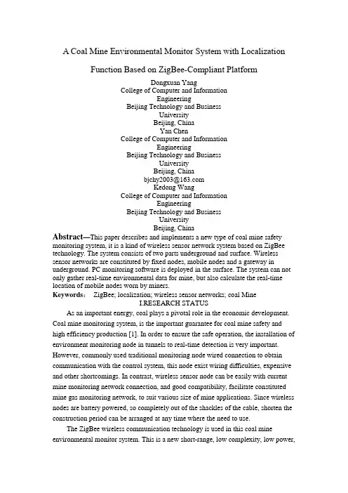
A Coal Mine Environmental Monitor System with LocalizationFunction Based on ZigBee-Compliant PlatformDongxuan YangCollege of Computer and InformationEngineeringBeijing Technology and BusinessUniversityBeijing, ChinaYan ChenCollege of Computer and InformationEngineeringBeijing Technology and BusinessUniversityBeijing, China*****************Kedong WangCollege of Computer and InformationEngineeringBeijing Technology and BusinessUniversityBeijing, ChinaAbstract—This paper describes and implements a new type of coal mine safety monitoring system, it is a kind of wireless sensor network system based on ZigBee technology. The system consists of two parts underground and surface. Wireless sensor networks are constituted by fixed nodes, mobile nodes and a gateway in underground. PC monitoring software is deployed in the surface. The system can not only gather real-time environmental data for mine, but also calculate the real-time location of mobile nodes worn by miners.Keywords:ZigBee; localization; wireless sensor networks; coal MineI.RESEARCH STATUSAs an important energy, coal plays a pivotal role in the economic development. Coal mine monitoring system, is the important guarantee for coal mine safety and high efficiency production [1]. In order to ensure the safe operation, the installation of environment monitoring node in tunnels to real-time detection is very important. However, commonly used traditional monitoring node wired connection to obtain communication with the control system, this node exist wiring difficulties, expensive and other shortcomings. In contrast, wireless sensor node can be easily with current mine monitoring network connection, and good compatibility, facilitate constituted mine gas monitoring network, to suit various size of mine applications. Since wireless nodes are battery powered, so completely out of the shackles of the cable, shorten the construction period can be arranged at any time where the need to use.The ZigBee wireless communication technology is used in this coal mine environmental monitor system. This is a new short-range, low complexity, low power,low data rate, low-cost two-way wireless communication technology [2]. Now, wireless sensor network product based on ZigBee technology are quantity and variety, but the real product can be applied in underground environments of special sensor node is very few[3]. The sensor node that we designed in the system is truly able to apply to in-well environment, it through the wireless sensor node security certification. At the same time, due to the special nature of the wireless network is that it can spread the wireless signal, we can easily locate staff for coal mine safety monitoring provides more protection [4].II. SYSTEM ARCHITECTUREThis system is a comprehensive monitoring system which is combined with software and hardware. Hardware part includes wireless mobile nodes and fixed nodes which were deployed in the underground tunnel, the main function of them is to collect coal mine environment data and require person’s location. Software part refers to the PC monitoring software which is designed in VC++ is used to summarize and display the data of each node. Monitoring node is divided into mobile nodes and fixed nodes; they are using ZigBee protocol for wireless transmission of data. Because the fixed node is also using wireless data transmission method, so it's deployed in the underground roadway becomes very convenient. As the mobile node is carried by the miner, it must be using wireless transmission method. This allows the mine to form a topology of ZigBee wireless sensor network. The fixed node in wireless sensor network is router device and the mobile node carried by miner is the end device. Normally, the router of ZigBee network has no sensor equipment; it is only responsible for data forwarding. But considering the practical application, we believe that add sensor devices on the router will be better on monitoring underground coal mine environment. So in our design, the router also has an environment monitoring function which is usually designed in end device.Fixed node will sent received data from mobile node to the gateway, then the gateway transmits data to monitor computer through RS232 or optical fiber. The PC monitor software in the computer will process all data and display them in a visualization window. The PC software also calculates each mobile node’s real-time location through the specific localization algorithm, according to the received signal strength (RSSI) obtained from mobile nodes.III. NODE DESIGNSince the ZigBee wireless network platform sold on present market was designed for the general environment, for special underground so they are not suitable for the environment. Therefore, we need to customize the system for underground environment whit a special hardware circuit. Node photo are shown in Fig. 1 Then wireless microcontroller CC2530 chip is the core processor of the node device, it can constitute a ZigBee network with very few peripheral circuits. TheCC2530 is an IEEE 802.15.4 compliant true System-on-Chip, supporting theproprietary 802.15.4 market as well as the ZigBee, ZigBee PRO, and ZigBee RF4CE standards. Unlike other wireless chip, CC2530 built-in 8051 monolithic integrated circuits kernel, therefore we no longer need to use a single MCU to control the circuit, and this save us a lot of cost [5].A.Mobile NodeThe mobile node is the end device of a ZigBee network that can be carried by miner; it should be a portable and low power consumption node. So the mobile node we designed is only as small as a mobile phone, and it is by built-in lithium ion battery power supply. In power loss, the core processor CC2530 is a low power consumption chip, when it is in the sleep mode, it only need to use less then 1uA work current. In order to reduce power consumption as much as possible on the display, a 100*32 pixel matrix with no backlighting LCD screen was used. The battery’s capacity of the mobile node is 1500mAh,so it is enough to meet the miner’s long hour works in the underground. The battery charge management chip is TP4057, the maximum charge current can up to 500Ma.Figure 1. Node photo.The mobile node circuit includes the gas concentration sensor MJ4.0 and temperature sensor PT-1000. As far as we know, many wireless sensor platforms use the digital type sensor. The communication between the digital sensor and the MCU need strict timing requirements. But considering the actual application, the wireless MCU usually has a real-time operating system in general, if we use the microcomputer to simulate the strict timing, it will affect the real-time of whole operating system. These two sensors output analog signals not digital signals. Only input this signal into a differential amplifier, can we get an appropriate signal that can be converted to a digital signal by an ADC mode within the CC2530 chip. In order to facilitate the carrying, external antenna was not used in our mobile node, instead ofusing a 2.4GHz patch antenna. And we customize a shell like a cell phone size; it is enough to put all PCBs, sensors and battery in it. Taking into account the small shell of the explosive performance is not very good, the design of PCBs and the selection of component are all carried out the safety assessment.B. Fixed NodeFixed node is installed in the wall of the underground tunnel. Because it is big than the mobile node, it is not appropriate to carry around. The circuit of the fixed node is almost same with the mobile node, it also use a CC2530 chip as core processor. Because of underground tunnels generally deploy with power cable, fixed nodes can use cable power-supply modes. At the same time, because we use wireless signal transmission, the deployment of new fixed nodes become very convenient, which also resolves the problem of the signal lines deployment.As a fixed node, the minor who is doing work may far from it, in order to facilitate the miners observed environmental data around the fixed nodes, it uses LED digital display. At the same time, the large current LED lights and buzzer are designed in the circuit; it makes the fixed node with the function of sound-light alarm. Considering that it may occur the emergency of without electricity, fixed node also built-in a lithium-ion battery. Under normal conditions, lithium-ion battery is in charging status, when external cable disconnect, fixed node is automatic switched to battery power, which can ensure the mobile node can deliver the information through fixed nodes in underground.Without regarding to fixed nodes’ portability, we have a customized shell that has excellent explosion properties, and the internal space is enough to hold down the 2.4 GHz antenna. To ensure safety, all cables and the location of sensors are placed with particular glue sealed, so that it has a good seal.IV.POSITIONING FUNCTIONOne of the important functions of the wireless sensor networks is localization, especially in the underground tunnel, it relates to the safe of the miner's life. Currently most widely used orientation method is GPS satellite positioning, it is a high precision, all-weather and global multifunctional system with the function of radio navigation, positioning and timing. But the GPS positioning method is not suitable for the underground work environment of coal mine, once you enter the underground, it cannot receive satellite signal, thus unable to achieve targeting [6]. We need to consider how to use wireless network to realize positioning function, means using wireless signal between the communications of devices for positioning. The existing distance measuring technology between the wireless-devices basically is the following kinds of methods: TOA, TDOA, AOA and RSSI.About the TOA method, the distance between the two devices is determined by the product of the speed of light and transmission time [7]. Although the precision of this method is accurate, but it require a precise time synchronization, so it demand hardware is higher.TDOA technology need ultrasonic signal,which is setting on a node with receive and transmit function. When measure the distance, it can sent ultrasonic wave and wireless signals together. By measuring the difference between two signals arrival time, we can calculate the distance between two devices [8]. Using this method can also obtain accurate result, but the method need to increase ultrasonic sending and receiving device on the node circuit, it will increase cost.AOA technology needs to install multiple antennas through the nodes so it canobtain adjacent nodes’ signals on deferent directions [9]. With this it can determine the location information from number of adjacent nodes and calculate its own position. This method not only need to add additional hardware, but also it's still very vulnerable to external disturbance, therefore it's not suitable for utilize.RSSI ranging is a cheap and easy technology. By using this method, we don't need to add additional hardware design. We also do not need very precise time requirements. This technique is about with measuring the wireless signals strength in the propagation of the loss, to measure the distance between two nodes. Because of this method requires hardware equipment is less, algorithm is simple, so it has been using in many wireless communication field. Comprehensive all conditions, positioning on the use of RSSI ranging technique.A. Hardware Location EngineThe CC2431 wireless microcontroller chip produced by TI Company has a hardware location engine. From the software's point of view, CC2431’s hardware location engine has a very simple API interface, as long as writing the necessary parameters and waiting for calculation, it can read the location results [10].The hardware location engine is also based on RSSI technology. The localization system includes reference nodes and blind nodes. The reference node is a fixed node that located in a known position, the node know their place and send a packet notifyto other nodes. The blind node receives packets from reference nodes, which can obtains reference nodes’ location and the corresponding RSSI value and put them into the hardware location engine, and then the blind node’s location can be read from the engine [11].On the surface, using the CC2431 hardware location engine targeting the program as a good choice, but considering the practical application, it will encounter the following problems. First of all, we have choose the CC2530 as the main chip of fixed nodes of the system, its internal programs is running in ZigBee2007 protocol, but CC2431 as a early chip, it applies only to ZigBee2006 protocol. In the communications between CC2431 and CC2530 that will have compatibility problems. Secondly, CC2431 hardware location engine use the distributed computing, all mobile nodes’ location are calculated by themselves, and then they upload information to the gateway node, this will not only occupy the mobile node processing time, still it can take up more network resources. For this reason, we have to shelve this approach, consider how to implement location by using CC2530 chip.B. Software Location EngineIf we want to use CC2530 to implement location function, that we must write software location engine by ourselves. Because that chip do not have a hardware location engine inside of it. This software location engine is still used RSSI technology; meanwhile mobile node position is calculated by the PC software, so asto reduce the burden of mobile node computing. To calculate the mobile node location, there must be at least three reference nodes. We will regard router nodes as reference nodes in network, and record the X, Y coordinates of every reference node. Then we let the mobile node send signal to each reference node, so that each reference node can obtain a RSSI values, with these parameters, we can use trilateral measurement method to calculate the specified location of the mobile node. The simpler way give the mobile node to broadcast way to send data, then around it every router node would receive the data from the mobile node, thus obtains RSSI values. Once the mobile node number increasing network, this method will make router nodes more burden, because the every radio message that the router node receives will transmit from the low layer to the top layer. Finally the application layer will analyze data packets. Infact, the mobile node need not to broadcast transmitted data, other routing node can also receive the mobile node packets. Only child mobile nodes of the router node will continue to transmit the packet forwarding upward, the other router nodes will shield out the packet in the bottom of the protocol.In order to let all router nodes can receive the packet which sending by mobile nodes, and send its RSSI values up to the gateway node, we need to modify the relevant function in Z- Stack protocol which is provided by TI. First we find the function named afIncomingData, it deals with the received data from the bottom of protocol, in which we add some code that can obtain packet’s RSSI value. Then through the osal_set_event function to add and send an eventMY_RSSI_REPORT_EVT of RSSI value task to OSAL polling system. This event’s corresponding function will be executed in the task of OSAL interrupt-driven function, thus the mobile node corresponding RSSI values will be sent to gateway node. Through this method, the packet will only be processed by bottom function of the protocol. According to this method we can obtain corresponding RSSI value and save the computation time of mobile nodes.In fact, this software location engine is not implementing with a single mobile node, but through the operation of the whole system to achieve. By which the mobile node is only responsible for sending unicast packets. The mobile node’s parent router node is responsible to forward the packet to the gateway. Other router nodes are not responsible for forwarding this packet, just clipping the mobile node of RSSI value, then forwarded to the gateway. Finally the gateway bring all RSSI values of the mobile node to PC monitoring software, the corresponding mobile node’s location is calculated. In order to reduce the error, monitoring software will collect 10 times of the RSSI value and take average on it, and then select the nearest value of the three fixed nodes. Finally the trilateral measurement method is used to calculate the location of mobile nodes.V.SYSTEM IMPLEMENTATIONAll software systems embedded in nodes are based on Z-Stack. BecauseZ-Stack is an open-source project, it is very beneficial to the secondary development. These nodes were tested in a real coal mine locate in Shanxi Province. We deployed the fixed node every 50 meters in the tunnel, and also set a fixed node in each entrance of the work area. Because the fixed node have large size digital LED displays, so the display content of the fixed node can be seen far from away the miner. Each miner carries a mobile node, the temperature and gas concentration is displayed on the LCD screen at real-time.The gateway node is placed at the entrance of the mine, through the RS232 cable connected to the monitoring computer in the control room. In this system all packets collected by the gateway node are transmitted to PC through a serial port, and it can save historical data backup to a SQL database. The main function of monitoring software is to display and store the data of every node, and calculates related mobile nodes’ location according to RSSI values. The monitoring software has two main dialog interfaces, one is used to display a two- dimensional profile of the coal mine, and user can see all the miners' working position. Another interface is data displaying interface, and environmental data were shown here. The picture of PC monitoring software is shown in Fig. 2.Figure 2. PC monitoring software.VI.SYSTEM EV ALUATIONThrough repeated testing of the system, we made the system an objective assessment. First is the power consumption assess for node hardware, fixed node’s working voltage is in 9V ~ 24V when the power supplied by cable. The maximum operating current for fixed node is 93mA; the average operating current is 92.2mA. When the power cable was disconnected, fixed node powered by lithium-ion battery. On battery power, the fixed node’s maximum working current is 147mA; average working current is 146.3mA. Fixed nodes can work 8 hours on battery power at least.Another quite important performance is the location function of the system performance. At four different locations of tunnel and working areas, mobile nodes were placed there. Two sets of different average error data were shown in From table 1. Because this system uses RSSI technology and it relies mainly on the signal strength, the signal quality will be affected by interferences. From different locations’ errors we can see that, the error in working areas was larger than it in tunnels, because the tunnel is generally straight, but the shape of the working areas are uncertainty.We gratefully acknowledge Texas Instruments for devices provided to us free of charge. And also thank staffs of XinNuoJin Company for giving us supports onsystem testing.REFERENCES[1] Xinyue Zhong Wancheng Xie. “Wireless sensor network in the coal mineenvironment monitoring“. Coal technology, 2009, Vol. 28, No. 9,pp.102-103. [2] Shouwei Gao. “ZigBee Technology Practice Guide”. Beijing: Beijing Universityof Aeronautics and Astronautics Press , 2009, pp. 27-28.[3] Yang Wang, Liusheng Huang, Wei Yang. “A Novel Real-Time CoalMinerLocalization and Tracking System Based on Self-Organized Sensor Networks”.EURASIP Journal onWireless Communications and Networking, Volume 2010, Article ID 142092.[4] Sang-il Ko, Jong-suk Choi, Byoung-hoon Kim. “Indoor Mobile LocalizationSystem and Stabilization of Localizaion Performance using Pre-filtering”.International Journal of Control, Automation and Systems, Vol. 6, No. 2, pp.204-213, April 2008.[5] .[6] Hawkins Warren, Daku Brian L. F, Prugger Arnfinn F. “Positioning inunderg round mines”. IECON 2006 - 32nd Annual Conference on IEEE Industrial Electronics, 2006, pp. 3159-3163.[7] Zhu, Shouhong, Ding, Zhiguo, Markarian Karina. “TOA based jointsynchronization and localization”. 2010 IEEE International Conference on Communications, ICC 2010, 2010, Article ID 5502036.[8] Ni Hao, Ren Guangliang, Chang Yilin. “A TDOA location scheme in OFDMbased WMANs”. IEEE Transactions on Consumer Electronics,2008, Vol. 54, No. 3, pp. 1017-1021.[9] Dogançay Kutluyil, Hmam Hatem. “Optimal angular sensor separation for AOAlocalization”. Signal Processing, 2008, Vol. 88, No. 5, pp. 1248-1260.[10] K. Aamodt. “CC2431 Location Engine”. Texas Instruments, Application NoteAN042, SWRA095.[11] Tennina Stefano, Di Renzo Marco, Graziosi Fabio, Santucci Fortunato.“Locating zigbee nodes using the tis cc2431 location engine: A testbed platform and new solutions for positioning estimation of wsns in dynamic indoor environments”. Proc Annu Int Conf Mobile Comput Networking, 2008, pp.37-42.摘要-本文介绍并设计了一个新类型的煤矿安全监控系统,它是一种基于ZigBee 技术的无线传感器网络系统。
无线通信5G介绍英文论文 A Brief Introduction About 5G Network
A Brief Introduction About 5G Network JiaAbstractWith the rapid development of wireless technologies, theconcept of the Fifth Generation (5G) wireless communication system started to emerge. But most people know little about 5G,including some aspects of 5G wireless communication networks ,just like what 5G is about: what are the building blocks of core 5G system concept, what are the main challenges and how to tackle them. Besides,A number of countries and organizations working on 5G, 5G development situation in China is of concern to everyone, China also needs to have its own place in such a competitive environment. Keywords:5G Network, history,Core concept, Challenges, Solutions, In chinaTable of Content1. Introduction................................................................................................................. - 3 -2. Research and development history ............................................................................. - 3 -3. Core Concept .............................................................................................................. - 4 -4. Challenges and Solutions............................................................................................ - 5 - 4.1 5G Transport Challenge ........................................................................................ - 6 - 4.2 5G Transport Challenge and some Solutions........................................................ - 7 - 4.3 Machine to Machine Communication................................................................... - 7 - 4.3 Core Network Virtualisation ................................................................................. - 8 -4.4 Summary............................................................................................................... - 8 -5. 5G In China................................................................................................................. - 9 - 5.5.1 White paper........................................................................................................ - 9 - 5.5.2 5G standards ...................................................................................................... - 9 - 5.5.3 China communications companies .................................................................... - 9 -5.5.4 Summary.......................................................................................................... - 10 -6. Conlusion.................................................................................................................. - 10 -7. Acronyms.................................................................................................................. - 11 -8. References................................................................................................................. - 11 -1. Introduction5G (Fifth-generation mobile communications) is a new generation of mobile communication mobile communication systems for 2020, with high spectral efficiency and low power consumption, in terms of transfer rate and resource utilization improvement over 4G system 10 times, its wireless coverage performance and user experience will be significantly improved. 5G will be closely integrated with other wireless mobile communication technology, constitute a new generation of ubiquitous mobile information network, to meet future mobile Internet traffic 1000x development needs in 10 years.[1]In this paper I will show you some latest research and development history,what are the building blocks of core 5G system concept, what are the main challenges and how to tackle them firstly. In the rest of paper I will show how 5G development in China in recent years and my conclusion after research literature.2. Research and development historyFebruary 2013, the EU announced that it would grant 50 million euros to accelerate the development of 5G mobile technology, plans to launch a mature standard in 2020. [2][3]May 13,2013,South Korea's Samsung Electronics Co., Ltd. announced that it has successfully developed the 5th generation mobile communication (5G) core technology, which is expected to begin in 2020 to commercialization. The technology can transmit data at ultra-high frequency 28GHz to 1Gbps per second speed, and the maximum transmission distance of up to 2 km. In contrast, the current fourth generation Long Term Evolution (4GLTE) and services of only the transmission rate 75Mbps. Prior to the transmission bottleneck is widely believed that a technical problem, while Samsung Electronics is the use of 64 adaptive array antenna elements transmission technology to crack this problem. Compared with the transmission speed of 4G technology in South Korea, 5G technology is hundreds of times faster. Using this technique, download a high-definition (HD) movie just need 10 seconds.Back in 2009, Huawei has launched the early research related technologies, and to show the prototype of the 5G base in later years.In November 6, 2013,Huawei announced that it would invest $600 million in 2018 for the 5G technology development and innovation, and predicted that users will enjoy 20Gbps commercial 5G mobile networks in 2020. May 8, 2014, the Japanese telecom operator NTT DoCoMo announced officially, Ericsson ,Nokia, Samsung and other six manufacturers to work together, began testing override 1000 times than existing 4G networks the carrying capacity of the high-speed network 5G network, the transmission speed is expected to 10Gbps. Outdoor testing scheduled to commence in 2015, and expects to begin operations in 2020.[3]March 1, 2015, the British "Daily Mail" reported that the British 5G network has successfully developed and tested for data transmission within 100 meters per second data transfer of up to 125GB, is 6.5 times the 4G network, in theory, a 30 seconds to download movies, adding that investment in public test in 2018, 2020 officially put into commercial use.[4]February 11, 2015 in the afternoon news, IMT-2020 (5G) to promote the group (hereinafter referred to as "advance group") held a conference in Beijing 5G concept of white paper. White Paper from the mobile Internet and networking composed mainly of application scenarios, business needs and challenges of starting summed continuous wide area coverage, high reliability of the four major technology 5G scene of high capacity, low power consumption and low latency connection. Meanwhile, the combination of core technologies and key capabilities 5G and 5G concept proposed by the "flag sexuality index + a set of key technologies" common definition.March 3,2015,the European Economic and Social Commission for Digital Furusawa Ottinge officially announced the EU's vision of public-private partnerships 5G, and strive to ensure that the right to speak in the next generation of mobile technology in Europe in the global standard.Ottinger said that, 5G vision of public-private partnership involves not only fiber, wireless or satellite communications network integrated with each other, will also use the software-defined networking (SDN), network functions virtualization (NFV), Mobile Edge computing (MEC) and Fog Computing technology. In the spectrum, the EU's vision of public-private partnership will be designated 5G hundreds of megahertz to improve network performance, 60 GHz and higher frequency bands will also be taken into account.A number of countries and organizations announced, 5G network will be operational between 2020 ~ 2025.3. Core ConceptWhat is 5G? I believe many people will be so questionable when see 5G. Judging from the word meaning, 5G refers to the fifth generation of mobile communications. However, how should it define? Currently, the global industry for 5G concept not yet agreed. China IMT-2020 (5G) group released the White Paper considers the concept 5G, 5G integrated key capabilities and core technology, 5G concept by "important targets" and "a group of key technologies" to a common definition. Among them, the flag indicators "Gbps rate user experience" is a set of key technologies, including large-scale antenna array, ultra-dense networking, new multi-site, full-spectrum access and new network architectures.Recalling the course of development of mobile communications, each generation ofmobile communication systems can be defined by sexual performance indicators and signs of key technologies. Wherein, 1G using FDMA, only analog voice services; 2G mainly using TDMA, can provide voice and low -speed digital data services; 3G to CDMA technology is characterized by user peak rate of 2Mbps to reach tens of Mbps, support multimedia data services; 4G OFDMA technology as the core, the user peak rate of up to 100Mbps ~ 1Gbps, can support a variety of mobile broadband data services.5G key competencies richer than previous generations of mobile communications, user experience, speed, density of connections, end to end delay, the peak rate and mobility and so will be the 5G key performance indicators. However, unlike the case in the past only to emphasize different peak rate, the industry generally believe that the rate of the user experience is the most important performance indicators, it truly reflects the real data rate available to the user, and the user experience is the closest performance. Based on the technology needs of the main scene 5G, 5G user experience rate should reach Gbps magnitude.Faced with diverse scenes of extreme performance demands differentiation, 5G cannot have solutions for all scenarios. In addition, the current wireless technology innovation has diversified development trend, in addition to the new multi -access technology, large -scale antenna array, ultra -dense network, the whole spectrum access, the new network architecture, also is considered to be the main technical direction.5G can play a key role in the major technology scene. [5]4. Challenges and SolutionsIn this part I outline some observed research challengesand directions in the mobile network development and show some may become the future trends and solutions that may lead to improved network performance while meeting the constantly increasing user demands. the new network architecture Gbps user exerperience rate Ultra -dense network Large -scale antenna array New multi -access technology The new network architecture Figure 1 - 5G Concept4.1 5G Transport ChallengeIn order to understand the 5G transport challenges one must understand how 5G may evolve the radio access segment.Among the various initiatives that are looking into 5G, we can defines 5G in terms of scenarios which the next generation wireless access networks will have to support. [6]A total of five future scenarios have been defined,namely amazingly fast (users want to enjoy instantaneous network connectivity), great service in a crowd, ubiquitous things communicating (i.e., effective support to Internet of Things), super real time and reliable connections, and best experience follows you. Each of these scenarios introduces a challenge .Three of these challenges (i.e., very high data rate, very dense crowds of users and mobility) are more traditional in the sense that they are related to continued enhancement of user experience and supporting increasing traffic volumes and mobility. Two emerging challenges, very low latency and very low energy, cost and massive number of devices, are associated with the application of wireless communications to new areas. Future applications may be associated with one or several of these scenarios imposing different challenges to the network. In METIS twelve specific test cases were defined and mapped onto the five scenarios. The selected test cases essentially sample the space of future applications. Once technical enablers that fulfill there quirements for these test cases are defined, it is expected that other applications subject to the same fundamental challenges, will successfully be supported. As a consequence, defining technical enablers for the 5G test cases means also defining technical solutions to the 5G challenges.While METIS[7] is focused on wireless access, the challenges defined for 5G are expected to impact also the transport. Support for very high data rates will require both higher capacity radio access nodes as well as a densification of radio access sites. This, in turn, translates into a transport network that needs to support more sites and higher capacity per site, i.e. huge traffic volumes. The great service in a crowd scenario will put requirements on the transport network to provide very high capacity on-demand to specific geographical locations. In addition, the best experience follows you scenario, suggests a challenge in terms of fast reconfigurability of the transport resources. On the contrary, the other 5G challenges are not expected to play as important role for shaping the transport, as for example the case of very low latency and very low energy, cost and massive number of devices. A properly dimensioned transport network based on modern wireless and/or optical technologies is already today able to provide extremely low latency, i.e., the end-to-end delay contribution of the transport network is usually almost negligible. In addition, while a huge number of connected machines and devices will create a challenge for the wireless network, it will most probably not significantly impact the transport. This is due to the fact that the traffic generated by a large number of devices over a geographical area will already be aggregated in the transport. The three scenarios for the transport network described above are summarized along with their corresponding challenges and test cases. Note that does not report all the original test cases but only those that pose challenges to the transport network. This information will be used later inthe paper to identify the appropriate transport technologies.4.2 5G Transport Challenge and some SolutionsThis section provides an overview of a number of transportoptions for 5G wireless networks. A 5G transport network can be divided in two different segments, i.e., small cell transportand metro/aggregation (Fig. 2). The small cell transport segment aggregates the traffic to/from the wireless small cells towards the metro/aggregation segment. Different solutions in terms of technology (e.g., optics, wireless) and topology (e.g., tree, ring, mesh) are possible depending on the specific wireless access scenario. The metro/aggregation segment, on the other hand, connects different site types (i.e., macro and/or small cells) among themselves and to the core network, the latter via the service edge (service node for the interconnection among different network domains).For the metro/aggregation segment one promising solution is represented by a dense-wavelength-division multiplexing (DWDM)[8] -centric network. In such a network, packet aggregation takes place at the edges of the network (e.g., at small/macro cells sites and at the service edge), while at center (i.e., between access and metro rings) switching is done completely in the optical domain thanks to active optical elements such as wavelength selective switches (WSSs) and reconfigurable optical add-drop multiplexers (ROADMs). It has already been demonstrated that DWDM-centric solutions have the potential to offer high capacity (in the order of tens to hundreds of Gbps) and lower energy consumption than their packet-centric counterparts (i.e., with packet aggregation at the center of the network). [9] For this reason the DWDM-centric metro/aggregation concept may represent a good candidate for future 5G transport networks.[10]4.3 Machine to Machine CommunicationMachine to Machine Communication Besides network evolution, we observe also device evolution that become more and more powerful. The future wireless landscape will serve not only mobile users through such devices as smartphones, tablets or game consoles but also a tremendous number of any other devices, such as cars, smart grid terminals, health monitoring devices and household appliances that would soon require a connection to the Internet. The number of connected devices will proliferate at a very high speed. It is estimated that the M2M traffic will increase 24-fold between 2012 and 2017 .[11]M2M communication is already today often used in fleet monitoring or vehicle tracking. Possible future usage scenarios include a wide variety of e-health applications and devices, for instance new electronic and wireless apparatus used to address the needs of elderly people suffering from diseases like Alzheimer’s, or wearable heart monitors. Suchsensors would enable patient monitoring and aid doctors to observe patients constantly and treat them in a better way. It will also reduce the costs of treatment, as it can be done remotely, without the need of going to a hospital.Remote patient monitoring using a Body Area Network (BAN), where a number of wireless sensors, both on-skin and implanted, record the patient’s health parameters and sends reports to a doctor, will soon become a reality and an important part of 5G paradigm. Therefore, in order to offer e-health services, 5G will need to provide high bandwidth, meet extremely high Quality of Service (QoS) requirements, e.g., ultra low latency and lossless video compression for medical purposes, and implement enhanced security mechanisms. Furthermore, extended work will need to be done to efficiently manage radio resources, due to high diversity of traffic types, ranging from the reports sent periodically by the meters, to high quality medical video transmission.4.3 Core Network VirtualisationMoving towards 5G imposes changes not only in the Radio Access Network (RAN) but also in the Core Network (CN), where new approaches to network design are needed to provide connectivity to growing number of users and devices. The trend is to decouple hardware from software and move the network functions towards the latter one. Software Defined Networking (SDN) being standardised by Open Networking Foundation (ONF) assumes separation of the control and data plane[12]. Consequently, thanks to centralization and programmability, configuration of forwarding can be greatly automated.Moreover, standardisation efforts aiming at defining Network Functions Virtualisation (NFV) are conducted by multiple industrial partners including network operators and equipment vendors within ETSI.[13] Introducing a new software based solution is much faster than installing an additional specialised device with a particular functionality. Both solutions would improve the network adaptability and make it easily scalable. As a result of simpler operation, one can expect more dynamic and faster deployment of new network features.4.4 SummaryI only list a partial of the challenges of 5G networks and possible solutions , in fact, before making a formal universal 5G are still many problems to be overcome, it also requires effort frontline researchers.5. 5G In China5.5.1 White paperFebruary 11, 2015,China released White paper about concept of 5G.It instantly make more people are concerned about 5G. People eager to 5G network as soon as possible. The White Paper published, the concept from various angles, core competencies, technical characteristics of 5G defined and interpreted. At the same time, this is the IMT-2020 (5G) to promote the group last year after the publication of the White Paper 5G vision and needs another masterpiece. The foreseeable future, as the Chinese government pay more attention to the development of 5G and adopt a more open attitude, with the joint efforts of the industry, and China will play an increasingly important role in the global 5G development, global industry will also be unified 5G standard stride forward.5.5.2 5G standardsChina will actively participate in the development of 5G standards, will help China to further enhance the patent position in international communication standards, escort for our mobile phone manufacturing.China is a big manufacturing country, the state has proposed the creation of a strategic shift to China, 3G and 4G standards successful experience will help us win more patents in the development of 5G standard time, to achieve the transformation of China to create the goal.5.5.3 China communications companiesFebruary 12, 2015, the International Telecommunication Union standard 5G start research work, and clearly the IMT-2020 work plan: will complete the IMT-2020 international standard preliminary studies in 2015, 2016 will be carried out 5G technical performance requirements and evaluation methods Research, by the end of 2017 to start collecting 5G candidate to complete standards by the end of 2020.It is worth noting that, in the 5G standards, Huawei, ZTE and other Chinese telecommunications companies such as Ericsson veteran communications companies also play an important role, in which Huawei from between 2013 to 2018, five years is ho throw $ 600 million 5G conduct research and innovation.Recently, ZTE 5G key technologies to achieve new progress. Following the end of the year to complete Massive MIMO antenna array massive field test, ZTE independently developed the proposed super dense network UDN, multiple users to share access to Multi-User Shared Access and other core technologies through demonstration, in Pre5G phase is expected to be applied.[14]Huawei CEO HuHouKun rotation, said in 2015, the company will spend the equivalent of about 10% in 2014 research and development budget, or $ 60 million, the development of 5G technology. Overall, the company's commitment in the next few years, $ 600 million investment in 5G technology. 5G is a next-generation mobile communications standard, is expected early in the next decade and put into use.[15]5.5.4 SummaryChina needs to have its own place in the 5G market, China's communications companies are also very hard, believe in the future, China's R & D level 5G will lead other countries.6. ConlusionIn this paper,I presented a summary of the concept,chanlleges,solusions and 5G in china.For 2020 and the future of the mobile Internet and networking business needs, 5G will focus on supporting the continuous wide area coverage, hot high-capacity, low power consumption and low latency connection highly reliable four main technical scenario, the use of large scale antenna array , ultra-dense networking, new multi-site, full-spectrum access and new network architectures, such as the core technology, through the evolution of new 4G air interface and two technical routes to achieve Gbps rate user experience, and to ensure consistency in service under a variety of scenarios .5G network to achieve real business there are a lot of unresolved issues. Also faced include how to design network architecture, including many technical challenges. Compared with previous generations of communications technology, 5G era biggest challenge is not how to increase the rate, but the user experience with traffic density, the number of terminals from a series of interwoven problems. As much as possible while also reducing user costs. This is the 5G network must be solved.5G study conducted in China are enthusiastic, China needs to accelerate the pace of its own 5G technology to get rid of dependence on foreign companies.5G study conducted in China are enthusiastic, China needs to accelerate the pace of its own 5G technology to get rid of dependence on foreign companies. 5G accelerate the development is conducive to China stand at the forefront of the competition in the next wave of data, a competitive advantage.7. Acronyms5G - Fifth-generation mobile communicationsSDN - software-defined networkingNFV - network functions virtualizationMEC - Mobile Edge computingFDMA - Frequency Division Multiple AccessTDMA - Time Division Multiple AccessCDMA - Code Division Multiple AccessOFDMA - Orthogonal Frequency Division Multiple AccessDWDM - dense-wavelength-division multiplexingBAN - Body Area NetworkQoS - Quality of ServiceRAN - Radio Access Network8. References[1]Chen Si ,Li Hua Sheng,”5G technology trends and challenges for radio management”, /news/41/a888991.html[2]”Samsung developed 5G technology”,/link?url=m_HOSi6QF36L7im-m0NRBaQggvikTgV0GLWBNy vN1OllSGp6_nYwU2B_fXsl6tEnyO0lXAw4Fnk0Ku0vtPSBMq#reference-[2]-764107 0-wrap[3] C114 China Communication Network,(Shanghai) ,March2015 ,”The EU announced 5G Vision: To guarantee the right to speak of global standards”/15/0311/10/AKE0JHMD000915BE.html[4]People’s Posts and Telecommunications News (PPTN),March,2015,”Bell Labs: 5G urgent task is to be completed as soon as possible standardization”/info/2015-03/11/c_134058306.htm[5] Baidu Encyclopedia,”5G network”/view/6220993.htm”[6] METIS deliverable D1.1, ”Scenarios, requirements and KPIs for 5G mobile and wireless system”, April 2013.[7] METIS deliverable D6.1, ”Simulation guidelines”, October 2013.[8] Shuqiang Zhang, Ming Xia, S. Dahlfort, ”Fiber routing, wavelength assignment and multiplexing for DWDM-centric converged metro/aggregation networks,” in Proc. of ECOC, Sept. 2013.[9] B. Skubic, I. Pappa, ”Energy consumption analysis of converged networks:Node consolidation vs metro simplification,” in Proc. of OFC,March 2013.[10] Matteo Fiorani,”Challenges for 5G Transport Networks”,IEEE,2014[11]Cisco, “Global Mobile Data Traffic Forecast Update,2012-2017,” Feb. 2013, White Paper.[12]Open Networking Foundation, “SDN Architecture Overview,” Dec. 2013.[13]ETSI, “Network Functions Virtualisation,” Oct. 2012, White Paper.[14]”ZTE 5G MUSA and UDN developed key technologies to achieve new progresss”/news/127/a892565.html[15]”Huawei will invest $ 600 million R & D 5G”/2015-04/02/content_543144.htm。
通信工程外文文献翻译
毕业设计(论文)的外文文献翻译原始资料的题目/来源:Fundamentals of wireless communications by David Tse翻译后的中文题目:无线通信基础专业通信工程学生王晓宇学号110240318班号1102403指导教师杨洪娟翻译日期2015年6月15日外文文献的中文翻译7.mimo:空间多路复用与信道建模本书我们已经看到多天线在无线通信中的几种不同应用。
在第3章中,多天线用于提供分集增益,增益无线链路的可靠性,并同时研究了接受分解和发射分解,而且,接受天线还能提供功率增益。
在第5章中,我们看到了如果发射机已知信道,那么多采用多幅发射天线通过发射波束成形还可以提供功率增益。
在第6章中,多副发射天线用于生产信道波动,满足机会通信技术的需要,改方案可以解释为机会波束成形,同时也能够提供功率增益。
章以及接下来的几章将研究一种利用多天线的新方法。
我们将会看到在合适的信道衰落条件下,同时采用多幅发射天线和多幅接收天线可以提供用于通信的额外的空间维数并产生自由度增益,利用这些额外的自由度可以将若干数据流在空间上多路复用至MIMO信道中,从而带来容量的增加:采用n副发射天线和接受天线的这类MIMO 信道的容量正比于n。
过去一度认为在基站采用多幅天线的多址接入系统允许若干个用户同时与基站通信,多幅天线可以实现不同用户信号的空间隔离。
20世纪90年代中期,研究人员发现采用多幅发射天线和接收天线的点对点信道也会出现类似的效应,即使当发射天线相距不远时也是如此。
只要散射环境足够丰富,使得接受天线能够将来自不同发射天线的信号分离开,该结论就成立。
我们已经了解到了机会通信技术如何利用信道衰落,本章还会看到信道衰落对通信有益的另一例子。
将机会通信与MIMO技术提供的性能增益的本质进行比较和对比是非常的有远见的。
机会通信技术主要提供功率增益,改功率增益在功率受限系统的低信噪比情况下相当明显,但在宽带受限系统的高信噪比情况下则很不明显。
无线通信外文文献译文
无线通信电机及电子学工程师联合会2005年国际研讨会上关于微波,天线,传播和无线通信的电磁兼容技术在技术发展上的最新动态竹内清一地区10主任东京电机大学摘要本文介绍无线通信技术的最新发展趋势以及组成无线通信技术的四个部分。
第一个也是最重要的发展是全球互联网流量的增长。
在全球互联网流量增长的重要趋势总结在全球地理区域和他们的互联网渗透方面。
第二个部分是实现无线通信所必备的骨干网络中的硬件配套技术的发展。
第三部分是无线通信的中心问题,特别是本地个人用户,第四和最后一个部分是总结发言。
1简介许多技术的发展显然是需要通过无线通信的实现,以满足环保要求的社会背景需要这的种技术发展。
例如,互联网流量每年约增加一倍,而这种快速增长的互联网流量和WWW(全球资讯网)需要为骨干网络配置无线并不一定需要,但对本地无线通信的实现至关重要的巨大带宽。
骨干网主要靠光纤电缆的技术发展以及相关的配套技术配套支持运行的。
这样的等配套技术包括信息处理和WDM(波分复用)和他们使取得的高效无线通信成为了可能。
无线通信,特别是无线互联网特别是无线互联网对于集中,甚至不断移动的短距离范围内的本地个人用户非常重要。
在IEEE 802.11是无线局域网用于与合作媒介访问控制协议的一般原则,也可以扩展到其他类型的无线网络,如无线个人区域网络(WPAN的)。
该服务区的范围变得越来越小,以便让当地个人用户的充分利用无线通讯媒介用于无线互联网流量。
无线通信是无线互联网最便捷的传输介质,这种无线传输介质的有效使用是至关重要的。
可靠的访问几十兆赫可以跨相当大的在其中无线互联网将需要十倍多的细胞的语音系统的地理区域,每个这样的monocles将测量面积小,几十平方米的大约是百分之常规细胞的大小。
它比传统电池可以容纳更多给定的数据速率的有源器件。
为了使这成为可能的,有效的射频频谱空间复用是必要的,从而能够让个人用户访问更贴近低功率的传输点。
对于快速增长的互联网流量的整体通信系统可以由的三个关键的重要领域的技术发展来支持,1)硬件技术需要个人用户的高密度无线传输的实现,2)配套硬件技术的光纤电缆,3)整体通信系统的运作和维护方面的软件技术,我们主要回顾了前两部分的硬件方面2互联网的发展表1显示了最高的互联网普及率最高的24个国家。
通信工程 毕业设计 外文文献翻译:超宽带系统的数据通信
英文资料Ultra-Wideband Systems for Data CommunicationsG. Racherla, J.L. Ellis, D.S. Furuno, S.C. LinGeneral Atomics, Advanced Wireless Group10240 Flanders Ct. San Diego CA 92121WebsitABSTRACTUltra-Widebandt (UWB) is a radio transmission scheme that uses extremely low power pulses of radio energy spread across a wide spectrum of frequencies. UWB has several advantages over conventional continuous wave radio communications including potential support for high data rates, robustness to multipath interference and fading. We present an overview of UWB technology and its use in data communications and networking. We look at design considerations for UWB based networks at various layers of the protocol stack.1.INTRODUCTIONUltra-Wideband [1-6]一also known as baseband or impulse radio一is a carrier-free radio transmission that uses narrow, extremely low power pulses of radio energy spread across a wide spectrum of frequencies. UWB has recently gained a great deal of interest due to the recent Federal Communications Commission (FCC) Report and Order which allocates the UWB band一7.5 GHz of unlicensed spectrum for indoor and outdoor communication applications. UWB communications are required to have a -10 dB fractional bandwidth of more than 20% or a -10 dB bandwidth of more than 500 MHz [7]. It is important to note that the FCC has not defined a specific modulation scheme to be used. UWB systems offer the promise of high data rate, low susceptibilityto multipath fading, high transmission security low prime power requirements, low cost, and simple design [1,2,5,6].UWB has been used in military applications for the past several years for ground-penetrating precision radar applications and secure communications [3,8]. For the past few years, UWB has been developed for commercial applications [1,2,5,6]. With the recent FCC [7] report and order for theuse of UWB technology, there has been an added impetus to this endeavor. Other notable UWB applications include collision avoidance radar, tagging/identification; geolocation [9] and data communications in personal area networks (PAN) and local area network (LAN) environments.There are several future challenges to the wide adoption of UWB for wireless data communications including the infancy of the technology in the commercial arena, lack of reliablechannel models, the early stages of standardization effort and lack of low-cost system on chip (SoC) implementations. In this paper, we look at UWB technology for data communications and inside a UWB physical (PHY) layer characteristics. We also briefly introduce other related wireless standards such as 802.11 [10], 802.15.3 [11-13] Bluetooth [14], HomeRF [15] and HIPERLAN [16] and present a brief synopsis of the regulatory effort worldwide with special emphasis on the FCC. We also present the design considerations for UWB based data networking.2.ULTRA-WIDEBAND TECHNOLOGYThe basic waveform that employed in a UWB system is an approximation to an impulse, such as that shown in Fig. 1. The short duration of the pulse is associated with large inherent bandwidth; hence, the nomenclature "Ultra-Wideband". Typical attributes of UWB waveforms are summarized in Table 1.Fig. 1. UWB waveform example.The high spectral content of the UWB waveform gives rise to one of the primary advantages UWB operation for communications where a UWB system is robust against multipath fading[17] and narrowband interference [18]. In multipath fading, where the transmitted radio frequency (rt) signal can reflect off objects in its transmission path and can cause destructive interferences at the receiver, a loss of reception can occur. ThisTable 1: Characteristics of Typical UWB SystemsFractional Bandwidth > 20%Pulse Width 0.1-2 asPulse Repetition Frequency 1 kHz-2 GHzAverage Transmitted Power<1mWeffect is particularly problematic indoors where there are many reflecting surfaces. In the frequency domain, multipath is shown as frequency selective fading. Because UWB communications systems spreads the transmitted data over a broad frequency band if destructive interference occurs at a specific frequency, whether due to multipath or narrowband interference, the information can still be recovered over the good frequencies.UWB implementations can provide low complexity, low cost solutions [19], thus enabling vast deployments of the technology. A critical component that reaffirms a low cost solution is noting that UWB signals, being carrier-less, have greater simplicity over narrowband transceivers and require smaller silicon die sizes [20]. UWB can be designed to achieve very high bit rates while still achieving low power consumption, a feature set which will be exploited by the consumer electronics industry [21]. UWB schemes can further be designed to be very scalable in terms of complexity, bit rate, power consumption, and range.UWB technology can support many applications. Different UWB modulation schemes offer different advantages for communication, radar, and precisiongeo-location applications. UWB technology, which operates between 3.1 and 10.6 GHz, intrinsically offers an efficient reuse of precious spectrum by operating stealthily at the noise floor [22]. This UWB system operates at low power, to be compliant with operating under FCC Part 15 emissions, across a wide range of frequencies. As a spread spectrum technology, UWB offers a low probability of intercept and a low probability of detection [8]. Thus, it is particularly well suited for covert military or sensitive usage seenarios [8]. Because UWB signals have extremely short bursts in time (e.g., durations of 1 ns or less) they are suited for precision geo-location applications. Though UWB intrinsically offers the above-mentioned features, application optimization and improvements on these characteristics are left to specific designs and implementations, most notably by careful consideration of modulation schemes.2.1. UWB System Design ConsiderationsSeveral considerations are needed when designing a PAN. First, low power design is necessary because the portable devices within the network are battery powered. Second, high data rate transmission is crucial for broadcasting multiple digi\tal audio and video streams: Lastly, low cost is a prerequisite to broadening consumer adoption. In addition to these criteria, the UWB system designer must address synchronization and coexistence. Capturing and locking onto these short pulses make synchronization a non-trivial task. Coexisting peacefully with other wireless systems without interference is important;In particular, one needs to pay attention to the 802.1 la wireless LANs that operate in the 5 GHz ISM bands.At the physical layer, additional challenges lie in the transceiver and antenna design. At the transmitter, pulse shaping is required to produce flat and wideband emission in the desired frequency bands. Although new integrated circuits provide less expensive forms of integration, the pulses can be affected by the parasitics from the component and packaging [23]. To accommodate the high data rates, tradeoffs between high and low pulse repetition frequency (PRF) and modulation schemes must be considered. The low PRF system with higher modulation (more bits per symbol) may require a more complex receiver, while the high PRF system with lower modulation may lead to performance degradation for delay spread in the channel. Finally, traditional antenna designs gear towards narrow band systems. To avoid dispersion at the receiver, the new wideband antennas need phase linearity and a fixed phase center [23].3. UWB STANDARDIZATION ANDREGULATORY EFFORTSThere are several standards bodies presently considering, at some level, UWB technologies. The standards body most advanced in the consideration of UWB is study group "a" of IEEE 802.15.3, which was formed in November 2001 [11-13]. A serious effort is well underway to define a UWB channel model, and numerous UWB tutorials have been given. Many hallway conversations talk to a physical layer standard being ratified in 2004 (though there is no formal knowledge or position on this) and will accompany the soon to be approved 802.15.3 Medium Access Control (MAC) which supports quality of service (QoS) for real-time multimedia applications [12]. The technical requirements presently call for bit rates of 110 to 200 Mbps at ranges up to 10 m, with the option to achieve 480 Mbps possibly at shorter distances. The powerconsumption requirement is presently set at 100 to 250 mW with lOe 5 bit error rate at the top of the physical layer. Complexity/cost are presently expected to be comparable to Bluetooth and the physical layer is required to support four collocated piconets. Coexistence is presently crucial (e.g., IEEE 802.1 la) and the ability to scale the technology is key to a long lasting and widely adopted standard. These technical requirements come from documents that are still being revised; additionally, it is not possible to predict if proposals may fall short of meeting some of the desired requirements.The United States FCC issued a report and order in the early part of 2002. This landmark decision to permit UWB operation in the 3.1 to 10.6 GHz spectrum under Part 15 emis- sion limits, with some additional restrictions, has catalyzed development and standardization processes as is evident by the sheer number of entities (companies, academic and government institutions) associated with UWB and through the serious efforts of the IEEE 802.15.3 group. The FCC carefully chose the frequency band of operation to be above 3.1 GHz to avoid interfering with GPS and other life critical systems. Furthermore, the FCC ruled that emissions below Part 15 would pro-vide for peaceful coexistence, the ability to have narrowband and UWB systems collocated on a non-interfering basis, because unintentional emissions from devicessuch as laptops are also limited to Part 15 rules. This ruling makes it possible to have up to 15 UWB frequency bands in the 7.5 GHz allocated unlicensed spectrum [7]. Extensive efforts are being conducted throughout Europe (CEPT, ETSI, and the European Commission), Korea, and Japan (Association of Radio Industries and Businesses, and the Japanese Ministry of Telecommunications).4. NETWORKING WITH UWB SYSTEMSThere is a significant interest in the ability to perform location determination and tracking of assets and people throughout warehouses, factories, ships, hospita梦,business environments, and other buildings or structures. The ability for UWB technologies to operate within such intense multipath environments in conjunction with the ability for UWB to provide very accurate geo-location capability at low cost and long battery life justifies the increasing technological activity in this market [20].As the rf tags [24] are distributed, it is also recognized tha they can be coordinated and networked. To further reduce the cost of the transceivers, position determination can occur at networked computer terminals. Additionally, it is quite conceivable that tag complexity can be further simplified by installink transmitters that chirp periodically [8]. Just as UWB demonstrates many benefits for rf tags, the technology equally lends itself to distributed sensor networks [9]. Sensor network applications include feedback controls systems and environmental surveillance for commercial, industrial,_ and military applications.In the data communication area, UWB technology may be used to implement ad-hoc networks. An ad-hoc network [25-27] is characterized by a collection of hosts that form a network "on-the-fly". An ad-hoc network is a multi-hop wireless network wherein each host also acts as a router. Mobile TRANSPORT Ad-hoc NETworks (MANETs) [25-27] are ad-hoc networks wherein the wireless hosts have the ability to move. Mobility of hosts in MANETs has a profound impact on the topology of the network and its performance. Figure 2 illustrates how the various layers of the OSI protocol stack have to operate in order to successfully complete a communication session. We look at some of relevant design issues at the different layers for UWB-based sensor networks and MANETs.4.1. Design Issues for Layers of the Protocol StackThere are several design considerations of sensor networks setup (including rftags) [24]. The sensors typically work on batteries and need be low cost, low power, with LPI/LPD and the ability to do geo-location. All of these requirements are satisfied by a UWB PHY.The PHY layer [26,27] is a very complex layer which deals with the medium specification (physical, electrical and mechanical) for data transmission between devices. The PHY layer specifies the operating frequency range, the operating temperature range, modulation scheme, channelization scheme. channel switch time, timing, synchronization, symbol coding, and interference from other systems, carrier-sensing and transmit/receive operations of symbols and power requirements for operations. The PHY layer interacts closely with, the MAC sublayer to ensure smooth performance of the network. The PHY layer for wireless systems (such as MANETs) has special considerations to take into account as the wireless medium is inherently error-prone and prone to interference from other wireless and rf systems in the proximity. Multipath is important to consider when designing wireless PHY layer as the rf propagation environment changes dynamically with time; frequent disconnections may occur. The problem is exacerbated when the devices in the network are mobile because of handoffs and new route establishment. It should be noted that there is a concerted effort by several UWB companies muster supportfor a UWB-based high data rate PITY in the IEEE 802.15.3 working group.The data link layer consists of the Logical Link Control (LLC) and the MAC sub layers. The MAC sublayer is responsible for channel access and the LLC is responsible for link maintenance, framing data unit, synchronization, error detection and possible recovery, and flow control. The MAC sublayer tries to gain access to the shared channel to prevent collision and distortion of transmitted frames with frames sent by the MAC sublayers of other nodes sharing the medium. TheMAC sublayer in sensor networks and MANETs needs to be power-aware, self-organizing and support mobility and handoffs.The network layer of such networks should perform routing so as to minimize power and the number of node hops in the route. In some cases, flooding/gossiping may be required to increase chances of the packets reaching the destination. Data aggregation/fusion may be used for. data-centric routing [24] in the network layer. The network layer needs to allow for route maintenance and updates for fast changing network topology.The transport layer is responsible for the end-to-end integrity of data in thenetwork. The transport layer performs multiplexing, segmenting, blocking, concatenating, error detection and recovery, flow control and expedited data transfer. In the MANET environment, the mobility of the nodes will almost certainly cause packets to be delivered out of order and a significant delay in the acknowledgements is to be expected as a result. Retransmissions are very expensive in terms of the power requirements. Transport protocols for MANETs and sensor networks need to focus on the development of feedback mechanisms that enable the transport layer to recognize the dynamics of the network and adjust its retransmission timer, window size and perform congestion control with more information on the network.Fig. 2. Issues at each layer of the protocol stackThe application layer needs support for location-based services, network management, task assignment, query and data dissemination for sensor networks and possible MANETs.5. RELATED TECHNOLOGIESIn order to better understand UWB-based technologies, we look at some related technology standards. More information on these technologies can be found in Ref. 27.5.1. BluetoothBluetooth [14] is a short-range radio technology standard originallyintended as a wireless cable replacement to connect portable computers, wireless devices, handsets and headsets. Bluetooth devices operate in the 2.4 GHz ISM band. Bluetooth uses the concept of a piconet which is a MANET with a master device controlling one or several slave devices. Bluetooth also allow scatternets wherein a slave device can be part of multiple piconets. Bluetooth has beed designed to handle both voice and data. traffic.5.2. HIPERIANl1 and HIPERIANIlHIPERLAN/I and HIPERLAN/2 [16] are European wireless LAN (WLAN) standards developed by European Telecommunications Standards Institute (ETSI). HIPERLAN/1 is a wireless equivalent of Ethernet while HIPERLAN/2 has architecture based on wireless Asynchronous Transfer Mode (ATM). Both the standards use dedicated frequency spectrum at -5 GHz. HIPERLAN/I provides a gross data rate of 23.5 Mb/s and net data rate of more than 18 Mb/s while HIPERLAN/2 provides gross data rates of 6/16/36154 Mb/s and a maximum of 50 Mb/s net data rate. Both standards use 10/100/1000 mW of transmit power and have a maximum range of 50 m. Also, the standards provide isochronous and asynchronous services with support for QoS. However, they have different channel a-ss and modulation schemes.5.3. IEEE 802]]This IEEE family of wireless Etherdet standards is primarily intended for indoor and in-building WLANs. There are several varities of this standard. The current available versions are the 802.1 la, 802.11b and 802.llg (emerging draft standard) with other versions which are starting to show on the horizon [10]. The 802.11 standards support ad-hoc networking as well as connections using an access point (AP). The standard provides specifications of the PHY and the MAC layers. The MAC specified uses CSMA/CA for access and provides service discovery and scanning, link setup and tear down, data fragmentation, security, power management and roaming facilities. The 802.1 la PHY is similar to the HIPERLAN/2 PHY. The PHY uses OFDM and operates in the 5 GHz UNII band. 802.1 la supports data rates ranging from 6 to 54 Mbps. 802.11 a currently offers much less potential for rf interference than other PHYs (e.g., 802.11b and 802.11g) that utilize the crowded 2.4 GHz ISM band. 802.11 a can support multimedia applications in densely populated user environments.' The 802.11b standard, proposed jointly by Harris and Lucent Technologies, extends the 802.11 Direct Sequence Spread Spectrum (DSSS) PHY to provide 5.5 and 11 Mb/s data rates.5.4. IEEE 802.75.3The emerging draft standard [11-13] defines MAC and PHY (2.4 GHz) layer specifications for a Wireless Personal Area Network (WPAN). The standard is based on the concept of a piconet which is a network confined to a 10 m personal operating space (POS) around a person or object. A WPAN consists of one or more collocated piconets. Each piconet is controlled by a piconet coordinator (PNC) and may consist of devices (DEVs). The 802.15.3 PHY is defined for 2.4 to 2.4835 GHz band and has two defined channel plans. It supports five different data rates (11 to 55 Mb/s). The base uncoded PHY rate is 22 Mb/s5.5. HomeRFHomeRF [15] working group was formed to develop a standard for wireless data communication between personal computers and consumer electronics in a home environment. The HomeRF standard is technically solid, simple, secure, and is easy to use. HomeRF networks provide a range of up to 150 ft typically enough for home networking. HomeRF uses Shared Wireless Access Protocol (SWAP) to provide efficient delivery of voice and data traffic. SWAP uses a transmit power of up to 100 mW and a gross data rate of 2 Mb/s. It can support a maximum of 127 devices per network. A SWAP-based system can work as an ad-hoc network or as a managed network using a connection point6. CONCLUSIONIn this paper, we presented an overview of UWB technology and its characteristics and advantages over conventional, continuous wave transmissions. We presented how UWB is well suited for several applications like sensor networks and MANETs. UWB technology has garnered a lot of interest among vendors who are looking at standardizing the use of the technology in various forums including IEEE.中文翻译超宽带系统的数据通信G. Racherla, J.L. Ellis, D.S. Furuno, S.C. LinGeneral Atomics, Advanced Wireless Group10240 Flanders Ct.San Diego CA 92121E-mail: {gopal.racherla, jason.ellis, susan.lin,超宽带(UWB)是一种在宽频谱范围内使用超低功耗传播无线脉冲能量的无线电传输方案。
- 1、下载文档前请自行甄别文档内容的完整性,平台不提供额外的编辑、内容补充、找答案等附加服务。
- 2、"仅部分预览"的文档,不可在线预览部分如存在完整性等问题,可反馈申请退款(可完整预览的文档不适用该条件!)。
- 3、如文档侵犯您的权益,请联系客服反馈,我们会尽快为您处理(人工客服工作时间:9:00-18:30)。
无线通信外文翻译文献(文档含中英文对照即英文原文和中文翻译)译文:一种无线数据采集和传输系统的设计【摘要】在现代无线通信领域主要有一些技术为无线传输网络提供解决方法,例如:GSM,CDMA,3G,Wi-Fi。
这些方法使得网络能够高效率和高质量的工作,但是成本很高。
因此要低成本和在没有基础设施或者基础设施被破坏的情况下推广它们是很困难的。
根据这种情况,本论文中数据采集和无线传输网络里的信息终端和无线收发模块的关键部件,是依据nRF905收发模块和51系列单片机的原理设计而成作为核心硬件,此外,结合目前自组无线网络的技术,可以构建一个短距离无线数据采集和传输网络,这个网络能够提供一个工作在ISM(工业科学医学)频段的低功率及高性能的数据通信系统。
然后提出了一个对无线通信可行的解决方案,这个方案优势在于更强的实时响应,更高的可靠性要求和更小的数据量。
通过软件和硬件的调试和实际测量,这个系统在我们的解决方案基础上运行良好,达到了预期的目标并且已经成功的应用到无线车辆系统。
【关键词】自组网络;数据采集;传输网络1 简介在现代无线通信里,GSM,CDMA,3G和Wi-Fi因为其高速和可靠的质量而逐渐成为无线数据传输网络的主流解决方案。
它们也有高成本的缺点,因此如果广泛的应用,将会引起大量的资源浪费,也不能在小区域,低速率的数据通信中得到提升。
多点短距离无线数据采集和传输网络将成为最佳解决方案。
此系统支持点对点,点对多点和多点对多点通信系统的发展。
短距离无线通信可以适应各种不同的网络技术,例如蓝牙,IEEE802.11,家庭无线网和红外。
与远距离无线通信网络相比,它们的不同之处在于基本结构,应用水平,服务范围和业务(数据,语音)。
设计短距离无线通信网络的最初目的是为了提供短距离宽带无线接入到移动环境或者制定临时网络,这是在移动环境里互联网更深的发展。
短距离无线通信网络最主要的优势是更低的成本和更灵活的应用。
本文介绍信息终端(单个器件)的硬件和软件以及多点短距离无线数据采集和传输网络的无线接收模块的设计建议,提供一个低功率高性能的工作于ISM(工业科学医学)频段的无线数据通信系统。
文章剩余部分由如下内容组成:在第二部分,我们描述了无线数据采集和传输系统的通用模块图表,第三部分,我们分析此系统硬件设计的关键技术,第四部分,介绍系统的软件设计,第五部分,展示系统的测试结果,最后我们在第六部分阐述结论和进一步的工作。
2 系统实现模型1.系统模型作为一个点对多点的多功能无线通信系统,它包含了一个中央监控系统和多个远程终端单元(图1)。
实际上,远程终端单元是一些在移动过程中可互相通信的移动电台。
另外,中央监控系统与远程终端单元进行双向通信。
在下一部分,设计信息终端和控制中心的软件和硬件上的一些关键部件。
2.相关模型本论文中的系统是根据OSI(国际标准组织)中的OSI/RM模型里的第一层(物理层)和第二层(数据链路层)而设计的,如图2所示。
物理层的功能是通过建立电路和专用芯片组完成的。
然而通信协议里的数据链路层是由软件来实现的。
3 系统硬件设计为了设计,管理和更新的方便,一些硬件单元和节点根据它们的功能和电学特性被划分成不同的模型。
本设计以射频收发芯片nRF905为核心,以模块搭建设计为指导思想,搭建无线温度采集系统,系统主要由数据采集模块和无线传输模块组成。
数据采集模块以数字式温度传感器DSl8B20监测温度参数,并将监测的温度参数简单处理后通过nRF905无线模块发送到接收端口。
无线数据传输模块通过nRF905芯片进行数据收发处理,nRF905芯片的集成度较高,所需的外围器件较少,因此整体的电路设计相对比较简单点。
本设计给出其与MSP430F449的接口电路设计和接收端通过电平转换芯片MAX3232与PC机连接。
并根据硬件特性及连接设计相应的软件流程,并编写软件。
通过相适应的无线传输模块和数据采集模块控制软件的操控,保证整个硬件系统的流畅运作。
系统基本结构中包含无线射频收发模块,控制处理模块,通用串行接口模块,数据缓冲存储模块以及多功能电源管理模块等。
1.收发器和接收模块在数据发送过程中,数据包将被调制到高频然后发送到目标无线射频传输模块,接收过程中,高频信号通过无线射频接收模块又被解调成原始数据包。
NRF905是无线射频收发模块的关键,它的频率是16兆赫兹的晶体振荡器。
NRF905可以通过印刷式天线接收无线射频信号,但是为了提高接收机的灵敏度和抗干扰能力,这种模块也适用外部天线和滤波器电路。
2.控制处理模块控制处理模块包含MCU和外部电路,有两个功能:一是使所有模块在其控制下协调工作,二是处理和传输从接口来的数据,例如路由处理,数据打包,验证和重传请求。
模块的关键部件MCU是51系列单片机,考虑到工业功能,WINBOND 78LE546因其在8位CMOS微处理器里较好的容量特性被而被应用,与2.4-2.5伏的宽电压供电,256比特嵌入式RAM,16KB Flash EPROM以及64KB地址空间,四个8位标准I/O接口,一个标准I/O双串行口相兼容。
SCM的晶体振荡器频率是22.1184兆赫兹,电功率为3.3伏适合无线收发芯片里nRF905的逻辑水平。
它的引脚通过与VCC相连受到保护并保持器稳定性。
MCU与所有模块的具体连接如表1所示。
4 系统软件设计系统性能的真实取决于其有效性和合理的软件控制。
软件设计是在硬件环境的基础上开发一个无线网络协议,为了到达设计目标,这个协议要有诸如数据传输,冲突避免,错误后重传以及超时重试的功能。
整个网络由一个主机和许多分散的终端组成,每个终端必须有一个无线收发节点(此系统支持Nrf905单片无线收发器),整个无线网络的任何节点都有一个唯一认证地址对应一个唯一认证终端。
为了方便起见,每个确定系统的终端无线收发器节点地址都是我们自己设定的4字节。
为了提高系统的稳定性,协议被设置成停止-等待模式。
在数据链路层,发送过程大概如下:首先,数据源发送一个连接请求道数据目标,得到数据源的响应后传输数据。
接着,每一次传输都要等待接收方的回应。
如果响应正确,另一次的传输才会开始。
当所有数据传输完后,数据源将发送一个释放信道请求,当收到接收方的响应后传输结束。
接收过程如下:在接收方给数据源响应后将收到数据,然后会发送一个有效或无效的响应,直到收到拆除链路请求。
接下来,保存数据且发送一个响应来结束整个过程。
5 系统测试任何两个节点之间的通信大都可以通过点对点来测试,因此在系统测试过程中,A节点和B节点之间的通信模型对测试图解来说是一个很好的样本,就像图10。
闭环测试电路是通过PC带双串口以及两个RS32口和通信节点A和B建立起来的。
在一个终端,数据时通过串口测试辅助工具“串口助手V2.2”发送,在另一端,监控着返回的数据。
数据通过PC的串口A,RS32口发送,然后数据缓冲,最后成功到达终端无线收发器模块。
然而,数据接收过程是SPI串口,数据缓冲,然后RS32口,最后才是PC。
在本论文中,根据以收发器nRF905和51系列单片机作为核心硬件的原理设计一个低功耗高性能的无线数据通信系统。
提出无线数据通信一个可行的解决方案,这个解决方案适合于强大的实时响应,高可靠性要求和小数据量,被广泛的应用于各种领域,例如数据通信,环境监测和安全保卫系统。
我们相信在软件设计进一步精炼和提高以后集成和智能通信协议将会实现。
测试过程中,用数字示波器监测通信节点A、B,RS32口和SPI口的数据传输。
在接下来的部分,通过分析来自MOSI/SCK和MISO/SCK 的信息来验证系统的正确性。
6 总结在本论文中,根据以收发器nRF905和51系列单片机作为核心硬件的原理设计一个低功耗高性能的无线数据通信系统。
提出无线数据通信一个可行的解决方案,这个解决方案适合于强大的实时响应,高可靠性要求和小数据量,被广泛的应用于各种领域,例如数据通信,环境监测和安全保卫系统。
我们相信在软件设计进一步精炼和提高以后集成和智能通信协议将会实现。
原文:The Design of a Wireless Data Acquisitionand Transmission SystemAbstract—In the field of modern wireless communication, there are mainly some technologies that provide solutions to the wireless data transmission network, such as: GSM, CDMA, 3G, Wi-Fi.These solutions make network work with high efficiency and good quality, but still with high cost. So it was difficulty in popularizing in with low cost and at the circumstance of infrastureless or infrastructure destruction. According to this situation, in this paper, the key components of the Information Terminal and the wireless receiving modules on the data collection and wireless transmission network were designed with the principle of transceiver nRF905 and 51 series of single-chip computer as the core hardware, besides, combining with the current technology on the Wireless Ad Hoc Networks,a short-rang wireless data sampling and transmission network was putting up,which provides a low-powered and high-performance wireless data communication system, works in the ISM (Industrial Scientific Medical )Band.Then,an available solution to the wireless data communications was put forward, and this solution was good at stronger real-time response, higher reliability requirement and smaller data amount. Through software and hardware debugging and actual measuring, this system based on our solution had work well, reached the expected goal and been already successfully applied toWireless vehicle System.Index Terms—Ad Hoc Network;data acquisition; transmission network.I. INTRODUCTIONIn modern wireless communication,GSM,CDMA, 3G, and Wi-Fi become the mainstream solution of wireless data transmission network because of their high speed and reliable quality. They also have the shortcomings of high cost, so wider application would cause a great waste of resources, and they cannot be promoted in small regional, low speed data communications.Multi-point short-range wireless data collection and transmission network will be the best solution.The system supports the development of communication system of peer-to-peer, point-to-multipoint, and multipoint-to-multipoint. Short-range wireless communication can adopt different network technologies, such as Bluetooth [1], IEEE802.11 [2],HomeRF [3] and Infrared [4]. Compared with long-distance wireless communication network, they are different in the basic structure, the application level, service range, and business (data, voice). The originalintention of design of short-range wireless communication network is to provide short-distance broadband wireless access to mobile environment or formulation of temporary network, it is the further development of internet in mobile environment. The main advantage of short-range wireless communication network is lower cost and more flexible use. This paper presents the design proposal of hardware and software of information terminal (a machine) and wireless receiver module of multi-point short-range wirelessdata collection and transmission network, which provides a low-powered and high-performance wireless data communication system, works in the ISM (Industrial Scientific Medical)Band. The remainder of this paper is organized as follows. In Section Ⅱ, we describe the general block diagram of the wireless data acquisition and transmission system. In section Ⅲ, we analyze the key technologies about the system hardware design. In section Ⅳ, the system software design is introduced. In section Ⅴ, the testing results of system is presented. Finally, we present the conclusion and future work in Section Ⅵ.II. SYSTEM IMPLEMENTATION MODELA. System ModelAs a point to multi-points multi-mission wireless communication system, it consists of one central monitoring system (CMS) and Multiple Remote Terminal Units (RTU) (figure 1). In fact, this remote terminal unit is some kind of removable stations which can communicate with other stations in the process of motion. Furthermore, the CMS communicate with RTU in bidirectional way. In the next part, some pivotal segment on software and hardware of the information terminal and control center was designed.B. Reference ModelThe system in this paper is designed based on the first layer (the physical layer) and the second layer (the data link layer) of the architecture of OSI/RM (Open Systems Interconnection Reference Model) that the ISO (InternationalOrganization for Standardization) proposed, such as figure 2. The function of the physical layer is finished through constructing the circuit and special chips. Otherwise, communication protocols in the data link layer are realized by software.Ⅲ.THE HARDWARE DESIGN OF THE SYSTEMFor the sake of the convenience of design, maintenance and update, some hardware circuit cell and node was divided into some different module according to functional and electric characteristic. There are RF Transceiver module [5], controlling and dealing module, Universal Serial interface module, data buffer and storage module and multifunctional power management module in the basic structure (Figure 2). In the process of sending, the data package should been Modulated with High frequency and sent to object RF Transmitting module, in the process of receiving, the high frequency signal have been demodulated to original data package through the RF receiver module. NRF905 [5] is the key of RF Transceiver module whose frequency is 16MHz Crystal Oscillator. NRF905 can receive the RF signal by Printed Antenna, but this module adopts the external antenna and Filter Circuits in order to improve the receiver sensitivity and anti-jamming ability.B. Controlling and Treating modueThe controlling and treating module consists of MCU and external circuit, it have two functions: one made all module’s working under control and harmony; the other function is treating and transmitting the data got frominterface, such as router processing, data packaging, verification and repeating request. Module’s key MCU is 51 series microprocessor, and considering the industrial function, the WINBOND was applied in this practical experiment because of it’s good capability in 8-bit CMOS microprocessor, compatibility with 2.4-5.5V wide voltage electric supply, 256Bytes embedded RAM, 16KB Flash EPROM and 64KB addressing space, four 8 Bit standard I/O interfaces, one standard I/O dual serial interface. The Crystal Oscillator frequency of SCM is 22.1184MHz, and the electric power is 3.3V to adapting to nRF905 logical level in wireless transceiver chip. The impending PIN was protected by connecting with VCC to keeping its stability. The specific connection between MCU and all modules is described in TABLAE 1.C. Multifunctional Electric Power Management ModuleThe most remarkable characteristic is compatibility with 8-24V wide voltage electric supply including CMOS power and TTL power, respectively in 5V and 3.3V, which provided all modules with the suitable and stable power. Meanwhile,it means so much in energy source saving because of its electronic switch. The power supply transfer chip C851414 and AS-1117-3.3 is the primary ingredient in this module.The C851414 made the electric voltage transfer from 8V to 24V, then, the AS-1117-3.3 made it from 5V to 3.3V. Furthermore,suitable filter capacitance and inductance was introduced to make power’s ripple characteristic perfect as possible.D. Universal Serial Interface ModuleThe main function of Universal Serial interface module is connecting universal terminal equipment, such as signal output equipment or analog collection equipment with AD transfer. At the same time, it provides entrance to the computer terminal data exchange through universal RS232 serial interface.E. Data Buffer and Storage ModuleIt has two kinds of function, one is data buffer, the other is data storage, respectively performed by 32KByte RAM and 16KByte EEPROM. Data buffer district supervise buffering some temporary data, such as transmit data, waiting data. Data storage district supervise some fixed data memory, such as router data, local host, local address and some renewed data for power-off protective. F. High Frequency Shielding Protecting Moudule In order to prevent electromagnetic interference from environment, circuit in our designing system is protected with metal enclosure. At the same time, preventing the digital circuit interfere from the radio frequency circuit in the system, we placed the two circuits in different isolated bin, such as figure 3. There is a small hole with diameter less than 1/4 wavelength in the metal box side, which is either easy to pass the line or prevent the electromagnetic wave from getting in it.Ⅳ.SYSTEM SOFTWARE DESIGNThe realization of system performance depends on its effective and reasonable software control. The design of this software is on the basis of the hardwareenvironment to development a wireless network protocol that have functions as data transmission, avoiding conflict, the retransmission when error occurs, and overtime retry, in order to achieve the design goal. The entire network is composed of a host and many scattered terminals, each terminal must have a wireless transceiver node (this system adopts nRF905 single-chip RF transceiver), any nodes of the entire wireless network has a unique identified address which is composed of an unique identified terminal. For convenience’s sake, each terminal wireless transceiver node addresse s of the actual system is set by ourselves (4 bytes). In order to improve the reliability of the system, the protocol is designed as stop-wait mode. In data link layer, the send process is roughly as follow. Firstly, the data sources send a connection request to the data targets, and it will transfer data after the data sources respond. Then wait for response from data target after each transmission. If the response is correct, another transmission will start. After all the data transmission is done, the data source will send a request to release channel resources, the transmission is finished when the response from the target is received. The receive process is as follow: the data target will receive data after give a response to the source, and will give a effective or uneffective response, until receive a demolition request. Then, save the data and send a response to end the entire process. data values are serially transferred, pumped into a shift register and are then internally available for parallel processing. Here we already see an important point, that must beconsidered in the philosophy of SPI bus systems: The length of the shift registers is not fixed, but can differ from device to device. Normally the shift registers are 8Bit or integral multiples of it. Of course there also shift registers with an odd number of bits. For example two cascaded 9Bit EEPROMs can store 18Bit data. If a SPI device is not selected, its data output goes into a high-impedance state, so that it does not interfere with the currently activated devices. When cascading several SPI devices, they are treated as one slave and therefore connected to the same chip select [5]. In figure 4 the cascaded devices are evidently looked at as one larger device and receive therefore the same chip select. The data output of the preceding device is tied to the data Ⅴ.SYSTEM TESTINGBecause communication between any two nodes may be tested through point to point, in this system Testing Process, communication model between node A and node B is a good example for testing schematic diagram, just like figure 10. Closed-loop testing circuit is put up through PC with double serial ports and two RS232 ports and communication node A and B. On one terminal, data was sent through serial port testing auxil iary tool “serial port assistant V2.2”, on the other terminal, returning data is monitored. Data is sent through PC’s serial port A, RS232 port, then data buffer and finally wireless transceiver module successively. However, the process of data receiving was SPI serial, data buffer, then RS232 port, finally PC. In t In this paper, a low-powered and high-performance wireless data communicationsystem were designed with the principle of transceiver nRF905 and 51 series of single-chip computer as the core hardware. An available solution to the wireless data communications was put forward, and this solution was good at stronger real-time response, higher reliability requirement and smaller data amount, which is widely applied various fields such as data communications, environmental monitoring and security Guard System. We believe that integrated and intelligent Communication Protocol are realized after software design is refined and improved further.he testing process, digital oscilloscope was also used to monitor the data transfer of communication node A , node B , RS232 port and SPI port. In the following section, information from MOSI/SCK and MISO/SCK was analyzed to verify the system’s Correctness. As a waveform of wireless sending data, figure 11 demonstrate some relations among efficient data, address information and synchronous clock in wireless sending process. Because the receiver address must be designated by the transmit terminal, 4 byte address require to be sent after sending packet.Ⅵ.CONCLUSIONIn this paper, a low-powered and high-performance wireless data communication system were designed with the principle of transceiver nRF905 and 51 series of single-chip computer as the core hardware. An available solution to the wireless data communications was put forward, and this solution was good at stronger real-time response, higher reliability requirement and smaller data amount, which is widely applied various fieldssuch as data communications, environmental monitoring and security Guard System. We believe that integrated and intelligent Communication Protocols are realized after software design is refined and improved further.TDD-CDMA systems to support asymmetric services by using directional antennas.。