外文文献翻译ZigBee:无线技术-低功耗传感器网络
ZigBee环境监测技术中英文资料对照外文翻译文献综述
ZigBee环境监测技术中英文资料对照外文翻译文献综述简介本文综述了有关ZigBee环境监测技术的中英文资料,并提供了对照的外文翻译文献。
ZigBee是一种低功耗的无线通信技术,特别适用于物联网应用中的环境监测。
通过对这些资料的对比和研究,可以更好地了解和应用ZigBee环境监测技术。
中文资料1. 许明宝, 胡永凡, 钟红民. 基于ZigBee的环境监测系统研究[J]. 现代检测技术, 2011, 31(1): 5-8.2. 杨洛, 李明洲. 基于ZigBee的温湿度监测系统设计[J]. 现代电子技术, 2012(9): 29-32.3. 谭勇, 王群, 李吉庆. 基于ZigBee的室内环境监测系统设计[J]. 仪器仪表学报, 2015, 36(3): 571-575.英文资料1. Wang, X., Hu, Z., & Hang, L. Wireless sensor network-based indoor temperature and humidity monitoring system using ZigBee technology[C]. 2020 6th International Conference on Control, Automation and Robotics (ICCAR), 2020: 100-105.2. Gao, J., Li, R., & Zhang, L. Study on wireless temperature and humidity monitoring system based on ZigBee[C]. 2019 4th International Conference on Green Technology and Sustainable Development (GTSD), 2019: 1-5.外文翻译文献1. 许明宝, 胡永凡, 钟红民. 基于ZigBee的环境监测系统研究(英文翻译). 现代检测技术, 2011, 31(1): 5-8. (Translation of "Research on ZigBee-based Environmental Monitoring System" by Xu Mingbao, Hu Yongfan, and Zhong Hongmin)2. 杨洛, 李明洲. 基于ZigBee的温湿度监测系统设计(英文翻译). 现代电子技术, 2012(9): 29-32. (Translation of "Design of ZigBee-based Temperature and Humidity Monitoring System" by Yang Luo and Li Mingzhou)3. 谭勇, 王群, 李吉庆. 基于ZigBee的室内环境监测系统设计(英文翻译). 仪器仪表学报, 2015, 36(3): 571-575. (Translation of "Design of ZigBee-based Indoor Environment Monitoring System" by Tan Yong, Wang Qun, and Li Jiqing)以上是有关ZigBee环境监测技术的中英文资料对照外文翻译文献综述。
外文原文
基于ZigBee技术农业无线温湿度传感器网络与农业生产实践相结合,提出了农业无线和湿度传感器网络设计,它基于ZigBee技术。
我们使用基于CC2530 ZigBee协议作为数据的采集,传输和显示的传感器节点和协调器节点的芯片,目的是实现农业生产自动化和精确农业。
关键词:农业,生产,温度和湿度,无线网络,传感器。
1.简介目前,生产和生活的许多方面都需要提取和加工周围环境的温度和湿度信息。
在过去的技术是收集温度和湿度传感器的温湿度信息,并通过RS-485总线或现场总线再次发送数据到监控中心,所以你需要铺设大量的电缆来收集温度和湿度信息。
传统农业主要使用孤立的机械设备,没有沟通能力,主要依靠的人来监控作物生长状况。
然而,如果使用ZigBee无线传感器网络技术,农业将逐步转变为信息和生产的为主的生产模式,使用更加自动化,网络化,智能化的耕作方式,实现远程无线控制设备。
传感器可以收集信息,如土壤水分,氮浓度,pH值,降水,温度,空气湿度,空气压力等。
采集到的上述信息和所收集信息的位置被传递到中央控制设备用于通过ZigBee网络的决策和参考,所以我们可以提前和准确地识别用于帮助维持和提高作物产量的问题。
在许多面向数据的无线网络传输,低成本和复杂性的无线网络被广泛地使用。
2. ZigBee的技术特点ZigBee技术是一种短距离,低复杂度,低功耗,低数据速率,和低成本,双向无线通信技术,主要是采用在自动控制和远程控制的领域中,可以嵌入各种设备中,以实现他们的自动化[1]。
对于现有的各种无线通信技术,ZigBee技术将是最低功耗和成本的技术。
ZigBee的数据传输速率低,在10KB/ s到250KB/ s的范围内,并主要集中在低速率传输。
在低功耗待机模式下,两个普通的5号电池可以持续6至24个月。
ZigBee的数据传输速率低,并且它的协议很简单,所以它大大降低了成本。
而它的网络容量大,可容纳65000设备。
延迟时间很短,一般在15毫秒〜30毫秒。
基于ZigBee技术的低功耗无线传感器网络研究
基于ZigBee技术的低功耗无线传感器网络研究随着物联网技术的不断发展,传感器网络作为物联网的基础技术之一,日益受到人们的关注。
而在众多的传感器网络技术中,基于ZigBee技术的低功耗无线传感器网络备受瞩目。
一、低功耗无线传感器网络的意义低功耗无线传感器网络(Low-Power Wireless Sensor Network,LPWSN)是指由一组分布在空间中,通过自组织方式协调工作,能够在自身资源限制下完成感知、处理和通信等多种任务的无线传感器节点构成的网络。
它将传感器作为节点,通过无线传输技术将数据传输到基站或信关站,实现对环境等参数的监测和感知。
低功耗无线传感器网络具有以下优点:1. 能够实现对环境等参数的精细感知。
2. 可以实现对环境进行长期监测,不需要人工干预。
3. 系统具有稳定性,能够在节点数量变化和节点失效的情况下正常运行。
4. 能够实现远距离、多节点的监控,应用范围广泛。
二、ZigBee技术ZigBee是一种低功耗、短距离的无线通信技术,它采用工业、科学、医疗电磁波频段(ISM频段)进行通信,可以用于传感器网络、智能家居、工业自动化等多种场景。
ZigBee技术主要具有以下特点:1. 低功耗。
ZigBee采用间歇性通信方式,使得节点在空闲状态下能够进入低功耗模式,从而大大延长节点的续航能力。
2. 网络形态灵活。
ZigBee可以实现星型、网状、集群等多种网络拓扑形态,适用于不同场景的需求。
3. 数据传输效率高。
ZigBee采用短数据帧进行数据传输,有效减少了传输时间和能耗。
4. 安全性高。
ZigBee使用AES-128加密算法,确保数据传输的安全性。
三、基于ZigBee技术的低功耗无线传感器网络研究目前,基于ZigBee技术的低功耗无线传感器网络已经在工业控制、室内环境监测等领域得到广泛应用。
下面详细探讨它在清洁能源和环境监测中的应用。
1. 清洁能源低功耗无线传感器网络可以实现对太阳能、风能等清洁能源的监测。
Zigbee无线传感器网络英文文献与翻译
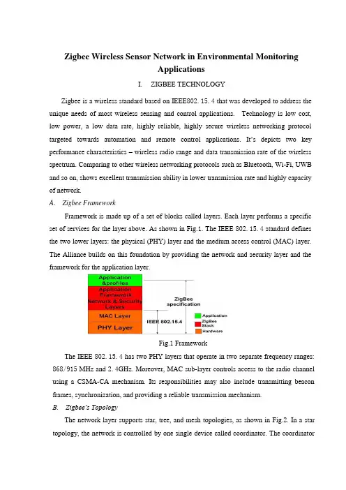
Zigbee Wireless Sensor Network in Environmental MonitoringApplicationsI. ZIGBEE TECHNOLOGYZigbee is a wireless standard based on IEEE802.15.4 that was developed to address the unique needs of most wireless sensing and control applications. Technology is low cost, low power, a low data rate, highly reliable, highly secure wireless networking protocol targeted towards automation and remote control applications. It’s depicts two key performance characteristics –wireless radio range and data transmission rate of the wireless spectrum. Comparing to other wireless networking protocols such as Bluetooth, Wi-Fi, UWB and so on, shows excellent transmission ability in lower transmission rate and highly capacity of network. A. Zigbee FrameworkFramework is made up of a set of blocks called layers.Each layer performs a specific set of services for the layer above. As shown in Fig.1. The IEEE 802.15.4 standard defines the two lower layers: the physical (PHY) layer and the medium access control (MAC) layer. The Alliance builds on this foundation by providing the network and security layer and the framework for the application layer.Fig.1 FrameworkThe IEEE 802.15.4 has two PHY layers that operate in two separate frequency ranges: 868/915 MHz and 2.4GHz. Moreover, MAC sub-layer controls access to the radio channel using a CSMA-CA mechanism. Its responsibilities may also include transmitting beacon frames, synchronization, and providing a reliable transmission mechanism.B. Zigbee’s TopologyThe network layer supports star, tree, and mesh topologies, as shown in Fig.2. In a star topology, the network is controlled by one single device called coordinator. The coordinator is responsible for initiating and maintaining the devices on the network. All other devices, knownas end devices, directly communicate with the coordinator. In mesh and tree topologies, the coordinator is responsible for starting the network and for choosing certain key network parameters, but the network may be extended through the use of routers. In tree networks, routers move data and control messages through the network using a hierarchical routing strategy. Mesh networks allow full peer-to-peer communication.Fig.2 Mesh topologiesFig.3 is a network model, it shows that supports both single-hop star topology constructed with one coordinator in the center and the end devices, and mesh topology. In the network, the intelligent nodes are composed by Full Function Device (FFD) and Reduced Function Device (RFD). Only the FFN defines the full functionality and can become a network coordinator. Coordinator manages the network, it is to say that coordinator can start a network and allow other devices to join or leave it. Moreover, it can provide binding and address-table services, and save messages until they can be delivered.Fig.3 Zigbee network modelII.THE GREENHOUSE ENVIRONMENTAL MONITORINGSYSTEM DESIGNTraditional agriculture only use machinery and equipment which isolating and no communicating ability. And farmers have to monitor crops’ growth by themselves. Even if some people use electrical devices, but most of them were restricted to simple communication between control computer and end devices like sensors instead of wire connection, which couldn’t be strictly defined as wireless sens or network. Therefore, by through using sensor networks and, agriculture could become more automation, more networking and smarter.In this project, we should deploy five kinds of sensors in the greenhouse basement. By through these deployed sensors, the parameters such as temperature in the greenhouse, soil temperature, dew point, humidity and light intensity can be detected real time. It is key to collect different parameters from all kinds of sensors. And in the greenhouse, monitoring the vegetables growing conditions is the top issue. Therefore, longer battery life and lower data rate and less complexity are very important. From the introduction about above, we know that meet the requirements for reliability, security, low costs and low power.A. System OverviewThe overview of Greenhouse environmental monitoring system, which is made up by one sink node (coordinator), many sensor nodes, workstation and database. Mote node and sensor node together composed of each collecting node. When sensors collect parameters real time, such as temperature in the greenhouse, soil temperature, dew point, humidity and light intensity, these data will be offered to A/D converter, then by through quantizing and encoding become the digital signal that is able to transmit by wireless sensor communicating node. Each wireless sensor communicating node has ability of transmitting, receiving function.In this WSN, sensor nodes deployed in the greenhouse, which can collect real time data and transmit data to sink node (Coordinator) by the way of multi-hop. Sink node complete the task of data analysis and data storage. Meanwhile, sink node is connected with GPRS/CDMA can provide remote control and data download service. In the monitoring and controlling room, by running greenhouse management software, the sink node can periodically receives the data from the wireless sensor nodes and displays them on monitors.B. Node Hardware DesignSensor nodes are the basic units of WSN. The hardware platform is made up sensor nodes closely related to the specific application requirements. Therefore, the most important work isthe nodes design which can perfect implement the function of detecting and transmission as a WSN node, and perform its technology characteristics. Fig.4 shows the universal structure of the WSN nodes. Power module provides the necessary energy for the sensor nodes. Data collection module is used to receive and convert signals of sensors. Data processing and control module’s functions are node device control, task sche duling, and energy computing and so on. Communication module is used to send data between nodes and frequency chosen and so on.Fig.4 Universal structure of the wsn nodesIn the data transfer unit, the module is embedded to match the MAC layer and the NET layer of the protocol. We choose CC2430 as the protocol chips, which integrated the CPU, RF transceiver, net protocol and the RAM together. CC2430 uses an 8 bit MCU (8051), and has 128KB programmable flash memory and 8KB RAM. It also includes A/D converter, some Timers, AES128 Coprocessor, Watchdog Timer, 32K crystal Sleep mode Timer, Power on Reset, Brown out Detection and 21 I/Os. Based on the chips, many modules for the protocol are provided. And the transfer unit could be easily designed based on the modules.As an example of a sensor end device integrated temperature, humidity and light, the design is shown in Fig. 5.Fig.5 The hardware design of a sensor nodeThe SHT11 is a single chip relative humidity and temperature multi sensor module comprising a calibrated digital output. It can test the soil temperature and humidity. The DS18B20 is a digital temperature sensor, which has 3 pins and data pin can link MSP430 directly. It can detect temperature in greenhouse. The TCS320 is a digital light sensor. SHT11, DS18B20 and TCS320 are both digital sensors with small size and low power consumption. Other sensor nodes can be obtained by changing the sensors.The sensor nodes are powered from onboard batteries and the coordinator also allows to be powered from an external power supply determined by a jumper.C. Node Software DesignThe application system consists of a coordinator and several end devices. The general structure of the code in each is the same, with an initialization followed by a main loop.The software flow of coordinator, upon the coordinator being started, the first action of the application is the initialization of the hardware, liquid crystal, stack and application variables and opening the interrupt. Then a network will be formatted. If this net has been formatted successfully, some network information, such as physical address, net ID, channel number will be shown on the LCD. Then program will step into application layer and monitor signal. If there is end device or router want to join in this net, LCD will shown this information, and show the physical address of applying node, and the coordinator will allocate a net address to this node. If the node has been joined in this network, the data transmitted by this node will be received by coordinator and shown in the LCD.The software flow of a sensor node, as each sensor node is switched on, it scans all channelsand, after seeing any beacons, checks that the coordinator is the one that it is looking for. It then performs a synchronization and association. Once association is complete, the sensor node enters a regular loop of reading its sensors and putting out a frame containing the sensor data. If sending successfully, end device will step into idle state; by contrast, it will collect data once again and send to coordinator until sending successfully.D. Greenhouse Monitoring Software DesignWe use VB language to build an interface for the test and this greenhouse sensor network software can be installed and launched on any Windows-based operating system. It has 4 dialog box selections: setting controlling conditions, setting Timer, setting relevant parameters and showing current status. By setting some parameters, it can perform the functions of communicating with port, data collection and data viewing。
Zigbee无线传感器网络英文文献

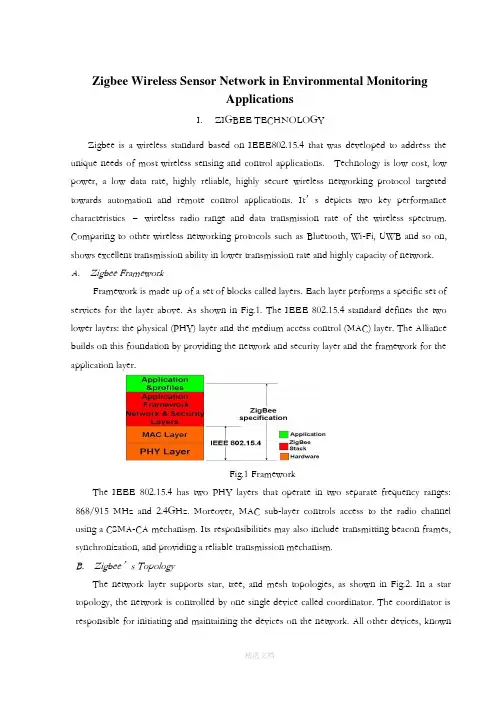
Zigbee Wireless Sensor Network in Environmental MonitoringApplicationsI. ZIGBEE TECHNOLOGYZigbee is a wireless standard based on IEEE802.15.4 that was developed to address the unique needs of most wireless sensing and control applications. Technology is low cost, low power, a low data rate, highly reliable, highly secure wireless networking protocol targeted towards automation and remote control applications. It’s depicts two key performance characteristics – wireless radio range and data transmission rate of the wireless spectrum. Comparing to other wireless networking protocols such as Bluetooth, Wi-Fi, UWB and so on, shows excellent transmission ability in lower transmission rate and highly capacity of network.A. Zigbee FrameworkFramework is made up of a set of blocks called layers.Each layer performs a specific set of services for the layer above. As shown in Fig.1. The IEEE 802.15.4 standard defines the two lower layers: the physical (PHY) layer and the medium access control (MAC) layer. The Alliance builds on this foundation by providing the network and security layer and the framework for the application layer.Fig.1 FrameworkThe IEEE 802.15.4 has two PHY layers that operate in two separate frequency ranges: 868/915 MHz and 2.4GHz. Moreover, MAC sub-layer controls access to the radio channel using a CSMA-CA mechanism. Its responsibilities may also include transmitting beacon frames, synchronization, and providing a reliable transmission mechanism.B. Zigbee’s TopologyThe network layer supports star, tree, and mesh topologies, as shown in Fig.2. In a star topology, the network is controlled by one single device called coordinator. The coordinatoris responsible for initiating and maintaining the devices on the network. All other devices, known as end devices, directly communicate with the coordinator. In mesh and tree topologies, the coordinator is responsible for starting the network and for choosing certain key network parameters, but the network may be extended through the use of routers. In tree networks, routers move data and control messages through the network using a hierarchical routing strategy. Mesh networks allow full peer-to-peer communication.Fig.2 Mesh topologiesFig.3is a network model, it shows that supports both single-hop star topology constructed with one coordinator in the center and the end devices, and mesh topology. In the network, the intelligent nodes are composed by Full Function Device (FFD) and Reduced Function Device (RFD). Only the FFN defines the full functionality and can become a network coordinator. Coordinator manages the network, it is to say that coordinator can start a network and allow other devices to join or leave it. Moreover, it can provide binding and address-table services, and save messages until they can be delivered.Fig.3 Zigbee network modelII.THE GREENHOUSE ENVIRONMENTAL MONITORINGSYSTEM DESIGNTraditional agriculture only use machinery and equipment which isolating and no communicating ability. And farmers have to monitor crops’ growth by themselves. Even if some people use electrical devices, but most of them were restricted to simple communication between control computer and end devices like sensors instead of wire connection, which couldn’t be strictly defined as wireless sens or network. Therefore, by through using sensor networks and, agriculture could become more automation, more networking and smarter.In this project, we should deploy five kinds of sensors in the greenhouse basement. By through these deployed sensors, the parameters such as temperature in the greenhouse, soil temperature, dew point, humidity and light intensity can be detected real time. It is key to collect different parameters from all kinds of sensors. And in the greenhouse, monitoring the vegetables growing conditions is the top issue. Therefore, longer battery life and lower data rate and less complexity are very important. From the introduction about above, we know that meet the requirements for reliability, security, low costs and low power.A. System OverviewThe overview of Greenhouse environmental monitoring system, which is made up by one sink node (coordinator), many sensor nodes, workstation and database. Mote node and sensor node together composed of each collecting node. When sensors collect parameters real time, such as temperature in the greenhouse, soil temperature, dew point, humidity and light intensity, these data will be offered to A/D converter, then by through quantizing and encoding become the digital signal that is able to transmit by wireless sensor communicating node. Each wireless sensor communicating node has ability of transmitting, receiving function.In this WSN, sensor nodes deployed in the greenhouse, which can collect real time data and transmit data to sink node (Coordinator) by the way of multi-hop. Sink node complete the task of data analysis and data storage. Meanwhile, sink node is connected with GPRS/CDMA can provide remote control and data download service. In the monitoring and controlling room, by running greenhouse management software, the sink node can periodically receives the data from the wireless sensor nodes and displays them on monitors.B. Node Hardware DesignSensor nodes are the basic units of WSN. The hardware platform is made up sensor nodes closely related to the specific application requirements. Therefore, the most important work is the nodes design which can perfect implement the function of detecting and transmission as a WSN node, and perform its technology characteristics. Fig.4 shows the universal structure of the WSN nodes. Power module provides the necessary energy for the sensor nodes. Data collection module is used to receive and convert signals of sensors. Data processing and control module’s functions are node device control, task sche duling, and energy computing and so on. Communication module is used to send data between nodes and frequency chosen and so on.Fig.4 Universal structure of the wsn nodesIn the data transfer unit, the module is embedded to match the MAC layer and the NET layer of the protocol. We choose CC2430 as the protocol chips, which integrated the CPU, RF transceiver, net protocol and the RAM together. CC2430 uses an 8 bit MCU (8051), and has 128KB programmable flash memory and 8KB RAM. It also includes A/D converter, some Timers, AES128 Coprocessor, Watchdog Timer, 32K crystal Sleep mode Timer, Power on Reset, Brown out Detection and 21I/Os. Based on the chips, many modules for the protocol are provided. And the transfer unit could be easily designed based on the modules.As an example of a sensor end device integrated temperature, humidity and light, the design is shown in Fig. 5.Fig.5 The hardware design of a sensor nodeThe SHT11is a single chip relative humidity and temperature multi sensor module comprising a calibrated digital output. It can test the soil temperature and humidity. The DS18B20 is a digital temperature sensor, which has 3 pins and data pin can link MSP430 directly. It can detect temperature in greenhouse. The TCS320is a digital light sensor. SHT11, DS18B20and TCS320are both digital sensors with small size and low power consumption. Other sensor nodes can be obtained by changing the sensors.The sensor nodes are powered from onboard batteries and the coordinator also allows to be powered from an external power supply determined by a jumper.C. Node Software DesignThe application system consists of a coordinator and several end devices. The general structure of the code in each is the same, with an initialization followed by a main loop.The software flow of coordinator, upon the coordinator being started, the first action of the application is the initialization of the hardware, liquid crystal, stack and application variables and opening the interrupt. Then a network will be formatted. If this net has been formatted successfully, some network information, such as physical address, net ID, channel number will be shown on the LCD. Then program will step into application layer and monitor signal. If there is end device or router want to join in this net, LCD will shown this information, and show the physical address of applying node, and the coordinator will allocate a net address to this node. If the node has been joined in this network, the data transmitted by this node will be received by coordinator and shown in the LCD.The software flow of a sensor node, as each sensor node is switched on, it scans allchannels and, after seeing any beacons, checks that the coordinator is the one that it is looking for. It then performs a synchronization and association. Once association is complete, the sensor node enters a regular loop of reading its sensors and putting out a frame containing the sensor data. If sending successfully, end device will step into idle state; by contrast, it will collect data once again and send to coordinator until sending successfully.D. Greenhouse Monitoring Software DesignWe use VB language to build an interface for the test and this greenhouse sensor network software can be installed and launched on any Windows-based operating system. It has 4 dialog box selections: setting controlling conditions, setting Timer, setting relevant parameters and showing current status. By setting some parameters, it can perform the functions of communicating with port, data collection and data viewing.Zigbee无线传感器网络在环境监测中的应用I.Zigbee技术Zigbee是一种基于IEEE802.15.4的无线标准上被开发用来满足大多数无线传感和控制应用的独特需求。
Zigbee无线传感器网络英文文献上课讲义
Zigbee Wireless Sensor Network in Environmental MonitoringApplicationsI. ZIGBEE TECHNOLOGYZigbee is a wireless standard based on IEEE802.15.4 that was developed to address the unique needs of most wireless sensing and control applications. Technology is low cost, low power, a low data rate, highly reliable, highly secure wireless networking protocol targeted towards automation and remote control applications. It’s depicts two key performance characteristics – wireless radio range and data transmission rate of the wireless spectrum. Comparing to other wireless networking protocols such as Bluetooth, Wi-Fi, UWB and so on, shows excellent transmission ability in lower transmission rate and highly capacity of network.A. Zigbee FrameworkFramework is made up of a set of blocks called layers.Each layer performs a specific set of services for the layer above. As shown in Fig.1. The IEEE 802.15.4 standard defines the two lower layers: the physical (PHY) layer and the medium access control (MAC) layer. The Alliance builds on this foundation by providing the network and security layer and the framework for the application layer.Fig.1 FrameworkThe IEEE 802.15.4 has two PHY layers that operate in two separate frequency ranges: 868/915 MHz and 2.4GHz. Moreover, MAC sub-layer controls access to the radio channel using a CSMA-CA mechanism. Its responsibilities may also include transmitting beacon frames, synchronization, and providing a reliable transmission mechanism.B. Zigbee’s TopologyThe network layer supports star, tree, and mesh topologies, as shown in Fig.2. In a star topology, the network is controlled by one single device called coordinator. The coordinatoris responsible for initiating and maintaining the devices on the network. All other devices, known as end devices, directly communicate with the coordinator. In mesh and tree topologies, the coordinator is responsible for starting the network and for choosing certain key network parameters, but the network may be extended through the use of routers. In tree networks, routers move data and control messages through the network using a hierarchical routing strategy. Mesh networks allow full peer-to-peer communication.Fig.2 Mesh topologiesFig.3is a network model, it shows that supports both single-hop star topology constructed with one coordinator in the center and the end devices, and mesh topology. In the network, the intelligent nodes are composed by Full Function Device (FFD) and Reduced Function Device (RFD). Only the FFN defines the full functionality and can become a network coordinator. Coordinator manages the network, it is to say that coordinator can start a network and allow other devices to join or leave it. Moreover, it can provide binding and address-table services, and save messages until they can be delivered.Fig.3 Zigbee network modelII.THE GREENHOUSE ENVIRONMENTAL MONITORINGSYSTEM DESIGNTraditional agriculture only use machinery and equipment which isolating and no communicating ability. And farmers have to monitor crops’ growth by themselves. Even if some people use electrical devices, but most of them were restricted to simple communication between control computer and end devices like sensors instead of wire connection, which couldn’t be strictly defined as wireless sens or network. Therefore, by through using sensor networks and, agriculture could become more automation, more networking and smarter.In this project, we should deploy five kinds of sensors in the greenhouse basement. By through these deployed sensors, the parameters such as temperature in the greenhouse, soil temperature, dew point, humidity and light intensity can be detected real time. It is key to collect different parameters from all kinds of sensors. And in the greenhouse, monitoring the vegetables growing conditions is the top issue. Therefore, longer battery life and lower data rate and less complexity are very important. From the introduction about above, we know that meet the requirements for reliability, security, low costs and low power.A. System OverviewThe overview of Greenhouse environmental monitoring system, which is made up by one sink node (coordinator), many sensor nodes, workstation and database. Mote node and sensor node together composed of each collecting node. When sensors collect parameters real time, such as temperature in the greenhouse, soil temperature, dew point, humidity and light intensity, these data will be offered to A/D converter, then by through quantizing and encoding become the digital signal that is able to transmit by wireless sensor communicating node. Each wireless sensor communicating node has ability of transmitting, receiving function.In this WSN, sensor nodes deployed in the greenhouse, which can collect real time data and transmit data to sink node (Coordinator) by the way of multi-hop. Sink node complete the task of data analysis and data storage. Meanwhile, sink node is connected with GPRS/CDMA can provide remote control and data download service. In the monitoring and controlling room, by running greenhouse management software, the sink node can periodically receives the data from the wireless sensor nodes and displays them on monitors.B. Node Hardware DesignSensor nodes are the basic units of WSN. The hardware platform is made up sensor nodes closely related to the specific application requirements. Therefore, the most important work is the nodes design which can perfect implement the function of detecting and transmission as a WSN node, and perform its technology characteristics. Fig.4 shows the universal structure of the WSN nodes. Power module provides the necessary energy for the sensor nodes. Data collection module is used to receive and convert signals of sensors. Data processing and control module’s functions are node device control, task sche duling, and energy computing and so on. Communication module is used to send data between nodes and frequency chosen and so on.Fig.4 Universal structure of the wsn nodesIn the data transfer unit, the module is embedded to match the MAC layer and the NET layer of the protocol. We choose CC2430 as the protocol chips, which integrated the CPU, RF transceiver, net protocol and the RAM together. CC2430 uses an 8 bit MCU (8051), and has 128KB programmable flash memory and 8KB RAM. It also includes A/D converter, some Timers, AES128 Coprocessor, Watchdog Timer, 32K crystal Sleep mode Timer, Power on Reset, Brown out Detection and 21I/Os. Based on the chips, many modules for the protocol are provided. And the transfer unit could be easily designed based on the modules.As an example of a sensor end device integrated temperature, humidity and light, the design is shown in Fig. 5.Fig.5 The hardware design of a sensor nodeThe SHT11is a single chip relative humidity and temperature multi sensor module comprising a calibrated digital output. It can test the soil temperature and humidity. The DS18B20 is a digital temperature sensor, which has 3 pins and data pin can link MSP430 directly. It can detect temperature in greenhouse. The TCS320is a digital light sensor. SHT11, DS18B20and TCS320are both digital sensors with small size and low power consumption. Other sensor nodes can be obtained by changing the sensors.The sensor nodes are powered from onboard batteries and the coordinator also allows to be powered from an external power supply determined by a jumper.C. Node Software DesignThe application system consists of a coordinator and several end devices. The general structure of the code in each is the same, with an initialization followed by a main loop.The software flow of coordinator, upon the coordinator being started, the first action of the application is the initialization of the hardware, liquid crystal, stack and application variables and opening the interrupt. Then a network will be formatted. If this net has been formatted successfully, some network information, such as physical address, net ID, channel number will be shown on the LCD. Then program will step into application layer and monitor signal. If there is end device or router want to join in this net, LCD will shown this information, and show the physical address of applying node, and the coordinator will allocate a net address to this node. If the node has been joined in this network, the data transmitted by this node will be received by coordinator and shown in the LCD.The software flow of a sensor node, as each sensor node is switched on, it scans allchannels and, after seeing any beacons, checks that the coordinator is the one that it is looking for. It then performs a synchronization and association. Once association is complete, the sensor node enters a regular loop of reading its sensors and putting out a frame containing the sensor data. If sending successfully, end device will step into idle state; by contrast, it will collect data once again and send to coordinator until sending successfully.D. Greenhouse Monitoring Software DesignWe use VB language to build an interface for the test and this greenhouse sensor network software can be installed and launched on any Windows-based operating system. It has 4 dialog box selections: setting controlling conditions, setting Timer, setting relevant parameters and showing current status. By setting some parameters, it can perform the functions of communicating with port, data collection and data viewing.Zigbee无线传感器网络在环境监测中的应用I.Zigbee技术Zigbee是一种基于IEEE802.15.4的无线标准上被开发用来满足大多数无线传感和控制应用的独特需求。
ZigBee外文文献加翻译
A Coal Mine Environmental Monitor System with LocalizationFunction Based on ZigBee-Compliant PlatformDongxuan YangCollege of Computer and InformationEngineeringBeijing Technology and BusinessUniversityBeijing, ChinaYan ChenCollege of Computer and InformationEngineeringBeijing Technology and BusinessUniversityBeijing, China*****************Kedong WangCollege of Computer and InformationEngineeringBeijing Technology and BusinessUniversityBeijing, ChinaAbstract—This paper describes and implements a new type of coal mine safety monitoring system, it is a kind of wireless sensor network system based on ZigBee technology. The system consists of two parts underground and surface. Wireless sensor networks are constituted by fixed nodes, mobile nodes and a gateway in underground. PC monitoring software is deployed in the surface. The system can not only gather real-time environmental data for mine, but also calculate the real-time location of mobile nodes worn by miners.Keywords:ZigBee; localization; wireless sensor networks; coal MineI.RESEARCH STATUSAs an important energy, coal plays a pivotal role in the economic development. Coal mine monitoring system, is the important guarantee for coal mine safety and high efficiency production [1]. In order to ensure the safe operation, the installation of environment monitoring node in tunnels to real-time detection is very important. However, commonly used traditional monitoring node wired connection to obtain communication with the control system, this node exist wiring difficulties, expensive and other shortcomings. In contrast, wireless sensor node can be easily with current mine monitoring network connection, and good compatibility, facilitate constituted mine gas monitoring network, to suit various size of mine applications. Since wireless nodes are battery powered, so completely out of the shackles of the cable, shorten the construction period can be arranged at any time where the need to use.The ZigBee wireless communication technology is used in this coal mine environmental monitor system. This is a new short-range, low complexity, low power,low data rate, low-cost two-way wireless communication technology [2]. Now, wireless sensor network product based on ZigBee technology are quantity and variety, but the real product can be applied in underground environments of special sensor node is very few[3]. The sensor node that we designed in the system is truly able to apply to in-well environment, it through the wireless sensor node security certification. At the same time, due to the special nature of the wireless network is that it can spread the wireless signal, we can easily locate staff for coal mine safety monitoring provides more protection [4].II. SYSTEM ARCHITECTUREThis system is a comprehensive monitoring system which is combined with software and hardware. Hardware part includes wireless mobile nodes and fixed nodes which were deployed in the underground tunnel, the main function of them is to collect coal mine environment data and require person’s location. Software part refers to the PC monitoring software which is designed in VC++ is used to summarize and display the data of each node. Monitoring node is divided into mobile nodes and fixed nodes; they are using ZigBee protocol for wireless transmission of data. Because the fixed node is also using wireless data transmission method, so it's deployed in the underground roadway becomes very convenient. As the mobile node is carried by the miner, it must be using wireless transmission method. This allows the mine to form a topology of ZigBee wireless sensor network. The fixed node in wireless sensor network is router device and the mobile node carried by miner is the end device. Normally, the router of ZigBee network has no sensor equipment; it is only responsible for data forwarding. But considering the practical application, we believe that add sensor devices on the router will be better on monitoring underground coal mine environment. So in our design, the router also has an environment monitoring function which is usually designed in end device.Fixed node will sent received data from mobile node to the gateway, then the gateway transmits data to monitor computer through RS232 or optical fiber. The PC monitor software in the computer will process all data and display them in a visualization window. The PC software also calculates each mobile node’s real-time location through the specific localization algorithm, according to the received signal strength (RSSI) obtained from mobile nodes.III. NODE DESIGNSince the ZigBee wireless network platform sold on present market was designed for the general environment, for special underground so they are not suitable for the environment. Therefore, we need to customize the system for underground environment whit a special hardware circuit. Node photo are shown in Fig. 1 Then wireless microcontroller CC2530 chip is the core processor of the node device, it can constitute a ZigBee network with very few peripheral circuits. TheCC2530 is an IEEE 802.15.4 compliant true System-on-Chip, supporting theproprietary 802.15.4 market as well as the ZigBee, ZigBee PRO, and ZigBee RF4CE standards. Unlike other wireless chip, CC2530 built-in 8051 monolithic integrated circuits kernel, therefore we no longer need to use a single MCU to control the circuit, and this save us a lot of cost [5].A.Mobile NodeThe mobile node is the end device of a ZigBee network that can be carried by miner; it should be a portable and low power consumption node. So the mobile node we designed is only as small as a mobile phone, and it is by built-in lithium ion battery power supply. In power loss, the core processor CC2530 is a low power consumption chip, when it is in the sleep mode, it only need to use less then 1uA work current. In order to reduce power consumption as much as possible on the display, a 100*32 pixel matrix with no backlighting LCD screen was used. The battery’s capacity of the mobile node is 1500mAh,so it is enough to meet the miner’s long hour works in the underground. The battery charge management chip is TP4057, the maximum charge current can up to 500Ma.Figure 1. Node photo.The mobile node circuit includes the gas concentration sensor MJ4.0 and temperature sensor PT-1000. As far as we know, many wireless sensor platforms use the digital type sensor. The communication between the digital sensor and the MCU need strict timing requirements. But considering the actual application, the wireless MCU usually has a real-time operating system in general, if we use the microcomputer to simulate the strict timing, it will affect the real-time of whole operating system. These two sensors output analog signals not digital signals. Only input this signal into a differential amplifier, can we get an appropriate signal that can be converted to a digital signal by an ADC mode within the CC2530 chip. In order to facilitate the carrying, external antenna was not used in our mobile node, instead ofusing a 2.4GHz patch antenna. And we customize a shell like a cell phone size; it is enough to put all PCBs, sensors and battery in it. Taking into account the small shell of the explosive performance is not very good, the design of PCBs and the selection of component are all carried out the safety assessment.B. Fixed NodeFixed node is installed in the wall of the underground tunnel. Because it is big than the mobile node, it is not appropriate to carry around. The circuit of the fixed node is almost same with the mobile node, it also use a CC2530 chip as core processor. Because of underground tunnels generally deploy with power cable, fixed nodes can use cable power-supply modes. At the same time, because we use wireless signal transmission, the deployment of new fixed nodes become very convenient, which also resolves the problem of the signal lines deployment.As a fixed node, the minor who is doing work may far from it, in order to facilitate the miners observed environmental data around the fixed nodes, it uses LED digital display. At the same time, the large current LED lights and buzzer are designed in the circuit; it makes the fixed node with the function of sound-light alarm. Considering that it may occur the emergency of without electricity, fixed node also built-in a lithium-ion battery. Under normal conditions, lithium-ion battery is in charging status, when external cable disconnect, fixed node is automatic switched to battery power, which can ensure the mobile node can deliver the information through fixed nodes in underground.Without regarding to fixed nodes’ portability, we have a customized shell that has excellent explosion properties, and the internal space is enough to hold down the 2.4 GHz antenna. To ensure safety, all cables and the location of sensors are placed with particular glue sealed, so that it has a good seal.IV.POSITIONING FUNCTIONOne of the important functions of the wireless sensor networks is localization, especially in the underground tunnel, it relates to the safe of the miner's life. Currently most widely used orientation method is GPS satellite positioning, it is a high precision, all-weather and global multifunctional system with the function of radio navigation, positioning and timing. But the GPS positioning method is not suitable for the underground work environment of coal mine, once you enter the underground, it cannot receive satellite signal, thus unable to achieve targeting [6]. We need to consider how to use wireless network to realize positioning function, means using wireless signal between the communications of devices for positioning. The existing distance measuring technology between the wireless-devices basically is the following kinds of methods: TOA, TDOA, AOA and RSSI.About the TOA method, the distance between the two devices is determined by the product of the speed of light and transmission time [7]. Although the precision of this method is accurate, but it require a precise time synchronization, so it demand hardware is higher.TDOA technology need ultrasonic signal,which is setting on a node with receive and transmit function. When measure the distance, it can sent ultrasonic wave and wireless signals together. By measuring the difference between two signals arrival time, we can calculate the distance between two devices [8]. Using this method can also obtain accurate result, but the method need to increase ultrasonic sending and receiving device on the node circuit, it will increase cost.AOA technology needs to install multiple antennas through the nodes so it canobtain adjacent nodes’ signals on deferent directions [9]. With this it can determine the location information from number of adjacent nodes and calculate its own position. This method not only need to add additional hardware, but also it's still very vulnerable to external disturbance, therefore it's not suitable for utilize.RSSI ranging is a cheap and easy technology. By using this method, we don't need to add additional hardware design. We also do not need very precise time requirements. This technique is about with measuring the wireless signals strength in the propagation of the loss, to measure the distance between two nodes. Because of this method requires hardware equipment is less, algorithm is simple, so it has been using in many wireless communication field. Comprehensive all conditions, positioning on the use of RSSI ranging technique.A. Hardware Location EngineThe CC2431 wireless microcontroller chip produced by TI Company has a hardware location engine. From the software's point of view, CC2431’s hardware location engine has a very simple API interface, as long as writing the necessary parameters and waiting for calculation, it can read the location results [10].The hardware location engine is also based on RSSI technology. The localization system includes reference nodes and blind nodes. The reference node is a fixed node that located in a known position, the node know their place and send a packet notifyto other nodes. The blind node receives packets from reference nodes, which can obtains reference nodes’ location and the corresponding RSSI value and put them into the hardware location engine, and then the blind node’s location can be read from the engine [11].On the surface, using the CC2431 hardware location engine targeting the program as a good choice, but considering the practical application, it will encounter the following problems. First of all, we have choose the CC2530 as the main chip of fixed nodes of the system, its internal programs is running in ZigBee2007 protocol, but CC2431 as a early chip, it applies only to ZigBee2006 protocol. In the communications between CC2431 and CC2530 that will have compatibility problems. Secondly, CC2431 hardware location engine use the distributed computing, all mobile nodes’ location are calculated by themselves, and then they upload information to the gateway node, this will not only occupy the mobile node processing time, still it can take up more network resources. For this reason, we have to shelve this approach, consider how to implement location by using CC2530 chip.B. Software Location EngineIf we want to use CC2530 to implement location function, that we must write software location engine by ourselves. Because that chip do not have a hardware location engine inside of it. This software location engine is still used RSSI technology; meanwhile mobile node position is calculated by the PC software, so asto reduce the burden of mobile node computing. To calculate the mobile node location, there must be at least three reference nodes. We will regard router nodes as reference nodes in network, and record the X, Y coordinates of every reference node. Then we let the mobile node send signal to each reference node, so that each reference node can obtain a RSSI values, with these parameters, we can use trilateral measurement method to calculate the specified location of the mobile node. The simpler way give the mobile node to broadcast way to send data, then around it every router node would receive the data from the mobile node, thus obtains RSSI values. Once the mobile node number increasing network, this method will make router nodes more burden, because the every radio message that the router node receives will transmit from the low layer to the top layer. Finally the application layer will analyze data packets. Infact, the mobile node need not to broadcast transmitted data, other routing node can also receive the mobile node packets. Only child mobile nodes of the router node will continue to transmit the packet forwarding upward, the other router nodes will shield out the packet in the bottom of the protocol.In order to let all router nodes can receive the packet which sending by mobile nodes, and send its RSSI values up to the gateway node, we need to modify the relevant function in Z- Stack protocol which is provided by TI. First we find the function named afIncomingData, it deals with the received data from the bottom of protocol, in which we add some code that can obtain packet’s RSSI value. Then through the osal_set_event function to add and send an eventMY_RSSI_REPORT_EVT of RSSI value task to OSAL polling system. This event’s corresponding function will be executed in the task of OSAL interrupt-driven function, thus the mobile node corresponding RSSI values will be sent to gateway node. Through this method, the packet will only be processed by bottom function of the protocol. According to this method we can obtain corresponding RSSI value and save the computation time of mobile nodes.In fact, this software location engine is not implementing with a single mobile node, but through the operation of the whole system to achieve. By which the mobile node is only responsible for sending unicast packets. The mobile node’s parent router node is responsible to forward the packet to the gateway. Other router nodes are not responsible for forwarding this packet, just clipping the mobile node of RSSI value, then forwarded to the gateway. Finally the gateway bring all RSSI values of the mobile node to PC monitoring software, the corresponding mobile node’s location is calculated. In order to reduce the error, monitoring software will collect 10 times of the RSSI value and take average on it, and then select the nearest value of the three fixed nodes. Finally the trilateral measurement method is used to calculate the location of mobile nodes.V.SYSTEM IMPLEMENTATIONAll software systems embedded in nodes are based on Z-Stack. BecauseZ-Stack is an open-source project, it is very beneficial to the secondary development. These nodes were tested in a real coal mine locate in Shanxi Province. We deployed the fixed node every 50 meters in the tunnel, and also set a fixed node in each entrance of the work area. Because the fixed node have large size digital LED displays, so the display content of the fixed node can be seen far from away the miner. Each miner carries a mobile node, the temperature and gas concentration is displayed on the LCD screen at real-time.The gateway node is placed at the entrance of the mine, through the RS232 cable connected to the monitoring computer in the control room. In this system all packets collected by the gateway node are transmitted to PC through a serial port, and it can save historical data backup to a SQL database. The main function of monitoring software is to display and store the data of every node, and calculates related mobile nodes’ location according to RSSI values. The monitoring software has two main dialog interfaces, one is used to display a two- dimensional profile of the coal mine, and user can see all the miners' working position. Another interface is data displaying interface, and environmental data were shown here. The picture of PC monitoring software is shown in Fig. 2.Figure 2. PC monitoring software.VI.SYSTEM EV ALUATIONThrough repeated testing of the system, we made the system an objective assessment. First is the power consumption assess for node hardware, fixed node’s working voltage is in 9V ~ 24V when the power supplied by cable. The maximum operating current for fixed node is 93mA; the average operating current is 92.2mA. When the power cable was disconnected, fixed node powered by lithium-ion battery. On battery power, the fixed node’s maximum working current is 147mA; average working current is 146.3mA. Fixed nodes can work 8 hours on battery power at least.Another quite important performance is the location function of the system performance. At four different locations of tunnel and working areas, mobile nodes were placed there. Two sets of different average error data were shown in From table 1. Because this system uses RSSI technology and it relies mainly on the signal strength, the signal quality will be affected by interferences. From different locations’ errors we can see that, the error in working areas was larger than it in tunnels, because the tunnel is generally straight, but the shape of the working areas are uncertainty.We gratefully acknowledge Texas Instruments for devices provided to us free of charge. And also thank staffs of XinNuoJin Company for giving us supports onsystem testing.REFERENCES[1] Xinyue Zhong Wancheng Xie. “Wireless sensor network in the coal mineenvironment monitoring“. Coal technology, 2009, Vol. 28, No. 9,pp.102-103. [2] Shouwei Gao. “ZigBee Technology Practice Guide”. Beijing: Beijing Universityof Aeronautics and Astronautics Press , 2009, pp. 27-28.[3] Yang Wang, Liusheng Huang, Wei Yang. “A Novel Real-Time CoalMinerLocalization and Tracking System Based on Self-Organized Sensor Networks”.EURASIP Journal onWireless Communications and Networking, Volume 2010, Article ID 142092.[4] Sang-il Ko, Jong-suk Choi, Byoung-hoon Kim. “Indoor Mobile LocalizationSystem and Stabilization of Localizaion Performance using Pre-filtering”.International Journal of Control, Automation and Systems, Vol. 6, No. 2, pp.204-213, April 2008.[5] .[6] Hawkins Warren, Daku Brian L. F, Prugger Arnfinn F. “Positioning inunderg round mines”. IECON 2006 - 32nd Annual Conference on IEEE Industrial Electronics, 2006, pp. 3159-3163.[7] Zhu, Shouhong, Ding, Zhiguo, Markarian Karina. “TOA based jointsynchronization and localization”. 2010 IEEE International Conference on Communications, ICC 2010, 2010, Article ID 5502036.[8] Ni Hao, Ren Guangliang, Chang Yilin. “A TDOA location scheme in OFDMbased WMANs”. IEEE Transactions on Consumer Electronics,2008, Vol. 54, No. 3, pp. 1017-1021.[9] Dogançay Kutluyil, Hmam Hatem. “Optimal angular sensor separation for AOAlocalization”. Signal Processing, 2008, Vol. 88, No. 5, pp. 1248-1260.[10] K. Aamodt. “CC2431 Location Engine”. Texas Instruments, Application NoteAN042, SWRA095.[11] Tennina Stefano, Di Renzo Marco, Graziosi Fabio, Santucci Fortunato.“Locating zigbee nodes using the tis cc2431 location engine: A testbed platform and new solutions for positioning estimation of wsns in dynamic indoor environments”. Proc Annu Int Conf Mobile Comput Networking, 2008, pp.37-42.摘要-本文介绍并设计了一个新类型的煤矿安全监控系统,它是一种基于ZigBee 技术的无线传感器网络系统。
ZigBee 中文翻译译文 含外文原文
毕业设计(论文)译文及原稿免费下载,免费分享。
让论文写得更简单,更舒适。
更容易……译文题目ZigBee:无线技术,低功耗传感器网络原稿题目ZigBee: Wireless Technologyfor Low-Power Sensor Networks原稿出处电子文献ZigBee:无线技术,低功耗传感器网络加里莱格美国东部时间2004年5月6日上午12:00技师(工程师)们在发掘无线传感器的潜在应用方面从未感到任何困难。
例如,在家庭安全系统方面,无线传感器相对于有线传感器更易安装。
而在有线传感器的装置通常占无线传感器安装的费用80%的工业环境方面同样正确(适用)。
而且相比于有线传感器的不切实际甚至是不肯能而言,无线传感器更具应用性。
虽然,无线传感器需要消耗更多能量,也就是说所需电池的数量会随之增加或改变过于频繁。
再加上对无线传感器由空气传送的数据可靠性的怀疑论,所以无线传感器看起来并不是那么吸引人。
一个低功率无线技术被称为ZigBee,它是无线传感器方程重写,但是。
一个安全的网络技术,对最近通过的IEEE802.15.4无线标准(图1)的顶部游戏机,ZigBee的承诺,把无线传感器的一切从工厂自动化系统到家庭安全系统,消费电子产品。
与802.15.4的合作下,ZigBee提供具有电池寿命可比普通小型电池的长几年。
ZigBee设备预计也便宜,有人估计销售价格最终不到3美元每节点,。
由于价格低,他们应该是一个自然适应于在光线如无线交换机,无线自动调温器,烟雾探测器和家用产品。
(图1)虽然还没有正式的规范的ZigBee存在(由ZigBee联盟是一个贸易集团,批准应该在今年年底),但ZigBee的前景似乎一片光明。
技术研究公司In -Stat/MDR在它所谓的“谨慎进取”的预测中预测,802.15.4节点和芯片销售将从今天基本上为零,增加到2010年的165万台。
不是所有这些单位都将与ZigBee结合,但大多数可能会。
外文Zigbee设计和实现一个低功耗无线个域网的无线温度湿度传感器网络
Design and Implementation of a Low-Power ZigBeeWireless Temperature Humidity Sensor NetworkShuipeng Gong1, Changli Zhang1,2, Lili Ma1, Junlong Fang1, and Shuwen Wang11 Northeast Agricultural University, Harbin, Heilongjiang Province,P.R. China, 150030,gongshuipeng@2 Northeast Agricultural University, Harbin, Heilongjiang Province, P.R. China, 150030,Tel.: +86-451-55190456,zhangcl@Abstract. The key technology of greenhouse facilities is the monitoring ofenvironmental parameters. Now, monitoring system of greenhouse is based onwire transmission. It is complicated to route wire and difficult to maintain. Alsoits reliability and anti-interference performance will degrade because of heat,light and acid. This paper leads a low-power and short range ZigBee techniqueinto greenhouse monitoring system. In order to compose intelligent networksensor system, the paper analyses the composition of network nodes powerconsumption, proposes low-power design method both in hardware andsoftware. The paper selects CC2430 module which composed of transceiver andmicroprocessor, and use SHT15 temperature humidity sensor. After hardwareand software debugging, this wireless network can acquire and transmit data ofgreenhouse temperature and humidity accurately and rapidly, and this systemresistant to stable work, tight structure, large loads and low power consumption.Keywords: Greenhouse, CC2430, ZigBee, Low-power, Temperature humiditysensor, Wireless network.1 IntroductionNow, monitoring system of greenhouse is based on wire transmission. It is complicated to route wire and difficult to maintain. Also its reliability and anti-interference performance will degrade because of heat, light and acid. As wire transmission brings many disadvantages, more and more monitoring systems use wireless sensor networks.ZigBee plays an important role in wireless sensor networks. ZigBee as a priority in wireless sensor networks because its advantages, such as low power consumption, high tolerance, Ad Hoc Networks [1].In normal ZigBee network nodes use portable power (battery). Its harsh environment and large quantities make it very difficult to replace. So reducing the power consumption and extending the reliable working hours of sensor nodes become one of the key considerations. To compose intelligent sensor network system, the paper analyzes the consumption of the network and proposed low-power consumption methods both form hardware and software.D. Li, Y. Liu, and Y. Chen (Eds.): CCTA 2010, Part IV, IFIP AICT 347, pp. 616–622, 2011.© IFIP International Federation for Information Processing 2011Low-Power ZigBee Wireless Temperature Humidity Sensor Network 617 2 System DesignThe system uses a tree topology and consists of coordinator, router and terminal node. Each router and terminal node carries temperature humidity sensor. The coordinator connects PC by RS-232 serial ports. It collects all nodes’ information and sends them to PC so that the manager can monitor and manage the information. Figure 3 shows the framework of the monitor system.Fig. 1. The system uses a tree topology. This shows the framework diagram of the monitor system.3 Low-Power Hardware DesignsThe hardware of the entire network includes coordinator and sensor nodes. Coordinator is powered by USB as coordinator connects with PC. So the low power strategy of the system mainly use in ZigBee nodes. ZigBee nodes are composed of processor module, wireless communication module, temperature humidity sensor module and power module. Figure 2 shows the structure of node.Fig. 2. The node is composed of CC2430, SHT15 and power modules618 S. Gong et al.3.1 Processor ModuleMicroprocessor is the central processing unit of the node. As the data that the microprocessor handled is large, the microprocessor is one of the most energy consuming components of the node. In the low power design, the microprocessor that the node used should be low power consumption and support sleep mode. As wireless communication account for most of the power consumption, the selection of the wireless module is very important. The following advantages of CC2430 make it become the ideal solution to solve the problem. CC2430 SoC integrates the CC2420 RF transceiver and enhanced 8051MCU. Its current consumption is 0.9uA on sleep mode and can be waked up by external interrupt or RTC wake-up system. Its current consumption is 0.6uA on dormancy mode and can be waked up by external interrupt. CCC2430 requires a large voltage supply between 2.0V and 3.6V [2].3.2 Sensor ModuleSensor module uses temperature humidity sensor module SHT15. SHT15 integrates temperature humidity sensor, the conditioning and amplifying, A/D converting and I2C bus in one chip.The serial interface of SHT15 has a definite advantage both on the reading of sensor signor and power consumption. Current consumption is 550uA in measuring, 28uA in average, 3uA during sleep.Fig. 3. This circuit diagram shows the interface of SHT15 and CC24303.3 Power ModulePower module is mainly for CC2430 and SHT15. Voltage range of CC2430 is 2.0-3.6V; the SHT15 is 2.4-5.5V.The power of the system uses 2 #5 battery (3V), we can get 3.3V for the system after using DC-DC L6920 step-up chip. The following advantages make L6920 become the best choice: output voltage is 3.3V or 5V, even when the input voltage as low as 0.7V the system still can work (This can make sure that after a period of time of battery usage and the input voltage is falling the output voltage is still 3.3V ). This can enhance the stability of the system. The power consumption of L6920 is low. The working current is 18uA and only 5uA on sleep mode. Figure 4 shows Power circuit.Low-Power ZigBee Wireless Temperature Humidity Sensor Network 619Fig. 4. Power circuit diagram shows that the 3.3V battery3.4 Processing of Spare PinsThe system uses the CMOS chips. The charges cumulated by spare pins make the potential between “0” and “1”. The current complementary consist of an enhanced NMOS and an enhanced PMOS, the jumping of the potential from “0” to “1” or “1” to “0” will make the two pins instant short [3]. The intermittent short will bring short consumption. So connecting spare pins to the ground can reduce power consumption.4 Low-Power Consumption of SoftwareWith the integrated circuit technological progress, power consumption of processor module and sensor module become very low. Figure 5 can explain the sensor node energy consumption, most of the energy consumption on wireless communication module; communication module has four states: transmitting, receiving, leisure and sleep, and energy consumption on transmitting, receiving and idle state is large, but the energy consumption on sleeping state is small [4]. So how to reduce power consumption on wireless communication has become an important problem.Fig. 5. This shows all the consumption of sensor node4.1 Working Mode of CC2430In general CC2430 has low power consumption, it offers four power modes to choose: PM0/ PM1 /PM2/ PM3.620 S. Gong et al.CC2430 works on full-function PM0 mode, the frequency is 32MHz and 32.768 kHz, and the power consumption is less than 1mW. When it works on sleep mode PM1/PM2, Only the 32.768 kHz low-speed crystal run, the power consumption is less than 0.9uA, when it works on Hibernate mode PM3, there is no crystal run, so the power consumption is less than 0.6uA.After sending information, the node will be run into PM2-sleep mode. Because in this mode, it can run into full-function mode through internal sleep clock wake-up, and it does not require manual operation to wake-up.When the system works on SET_POWER_MODE (2) mode, sleep time can be set. the frequency of PM2 mode is 32.768kHz,timer of sleep is a 24-bit counter, so the longest sleep time of system is: T=2*24/32768=512s,the shortest sleep time is: T=1/32768 and it is about 30.5us.The setting function of sleep time is Set_ST_Period (uint16 sec), where sec is set according to user needs.4.2 Low-Power Software DesignThe system wakes up nodes at regular time. Temperature and humidity is a gradual process, so it is no need to monitor it all the time. Monitoring it at regular time not only can monitor the change of temp and humidity, but also can reduce the working time of nodes. it is not necessary for the sensor nodes to communicate with coordinator all the time, this can avoid data collision and can reduce the power consumption.Fig. 6. This shows the flow chart of software design and the sleep mode of CC2430Low-Power ZigBee Wireless Temperature Humidity Sensor Network 621 After the establishment of ZigBee networks all sensor nodes send temp and humidity information to the coordinator. After receiving the confirmed information of coordinator the node gets into sleep mode. The coordinator connects to PC through RS-232 serial port. The temp and humidity information will display in upper machine. When the wake-up time arrives, the node will rouse from sleep and continue sending messages to coordinator. This method can make all nodes in sleep state in most of the time, which will significantly reduce the power consumption of the entire network. Figure 6 shows the flow chart of software design.5 Implement of ZigBee Sensor NetworkThe system uses a tree topology. The advantages of tree topology are as follows: it can extend transmission distance between coordinator and sensor nodes advance the ability to carry the load and enhance the area of the network.Fig. 7. This shows the results that the PC collects. The information is temperature and humidity of greenhouse.The connection of ZigBee coordinator and sensor nodes is bonding. Bonding is a mechanism from one application layer to another [5].2, 7, 8 are the labels of source nodes in the network, which can be determined when the program is downloaded. Each network ID is the only one in the network and each network ID correspond one sensor node [6]. We can monitor the temperature and humidity of the greenhouse through network ID. The power consumption of the nodes is 32.5mA in average.6 ConclusionZigBee wireless sensor network overcome many shortcomings that wired media bring in. This paper implements a ZigBee wireless sensor network that can transmit and622 S. Gong et al.monitor temperature and humidity of the greenhouse. This wireless sensor network resistant to stable work, tight structure, large loads and low power consumption.After low-power design, the power consumption of the network reduces, the effective working time of the sensor nodes extend and the stability of the system enhance.Each node can carry many sensors and controlled equipment, so the node can be added more sensor such as light sensor and CO2 sensor to collect more information of greenhouse.This ZigBee wireless sensor network is part of Internet of Things, and can be used in precision agriculture and industry and many other fields.Acknowledgments. Funding for this research was provided by Harbin Special Funds for Research on Technological Innovation Projects (NO.2008RFXXN003). References1.Bogena, H.R., Huisman, J.A., OberdÊrster, C., et al.: Evaluation of a low cost soil watercontent sensor for wireless network applications. Journal of Hydrology, 32–42 (2007)2.Zhang, X., Zhang, C., Fang, J.: Smart Sensor Nodes for Wireless Soil TemperatureMonitoring Systems in Precision Agriculture, pp. 237–240 (2009)3.Li, W., Duan, C.: ZigBee2007/PRO experiment and practice of stack. Press of BeihangUniversity, Beijing (2007)4.Gao, J.: Study of energy consumption of ZigBee wireless sensor network node. ElectronicTest, 1–4 (2008)5.Sun, Y., Liu, Z.C., Cai, C.: Design of Low-power wireless sensor networks nodes. ComputerApplications, 21–26 (2009)6.Li, J., Zhang, C., Fang, J.: Design On The Monitoring System Of Physical Characteristics OfDairy Cattle Based On Zigbee Technology. In: IEEE Proceedings of the 2009 International Conference on Computer and Computing Technology Applications in Agriculture (2010)。
ZigBee协议低功耗无线传感器网络的协议
ZigBee协议低功耗无线传感器网络的协议ZigBee是一种专为低功耗、短距离通信设计的无线传感器网络协议。
它基于IEEE 802.15.4标准,旨在提供稳定可靠的通信解决方案,适用于广泛的物联网应用。
本文将介绍ZigBee协议的特点、架构以及其在低功耗无线传感器网络中的应用。
一、ZigBee协议的特点1. 低功耗:ZigBee协议采用了低功耗设计,使得传感器节点的电池寿命得以延长。
这是通过快速进入和退出睡眠状态、低能耗的硬件设计以及优化的通信协议实现的。
2. 网络拓扑灵活:ZigBee支持多种网络拓扑结构,包括星型、网状和集群树等。
这种灵活性使得ZigBee网络能够适应不同应用场景的需求,提供多样化的通信方案。
3. 自组织组网:ZigBee节点可以通过自组织的方式建立和维护网络。
当一个节点加入网络时,它可以自动发现邻近节点并与之建立连接,从而形成一个可扩展的传感器网络。
4. 低成本:ZigBee协议所需的硬件资源相对较少,这使得ZigBee设备的制造成本低,适用于大规模部署。
二、ZigBee协议的架构ZigBee协议采用了分层的架构,包括应用层、网络层、MAC层和物理层。
1. 应用层:应用层定义了与应用程序相关的功能,如传感器数据的采集和处理、设备间的通信协议等。
它通过ZigBee集群库提供了一组标准的应用功能集,简化了应用程序的开发。
2. 网络层:网络层负责网络拓扑管理、路由选择和数据传输。
它定义了路由协议、维护网络表和路由表等功能,使得数据能够有效地在传感器节点之间传递。
3. MAC层:MAC层处理数据的传输和接收,通过帧格式的定义和超帧结构来实现。
它还负责低功耗的睡眠管理和信道访问控制,实现低功耗和高效的通信。
4. 物理层:物理层负责信号的调制、解调和发送。
ZigBee使用了2.4GHz无线频段,采用了多频道和直序扩频技术,提供了可靠的无线通信性能。
三、ZigBee在低功耗无线传感器网络中的应用ZigBee协议在低功耗无线传感器网络中有广泛的应用,包括家庭自动化、工业监测、农业环境监测等领域。
- 1、下载文档前请自行甄别文档内容的完整性,平台不提供额外的编辑、内容补充、找答案等附加服务。
- 2、"仅部分预览"的文档,不可在线预览部分如存在完整性等问题,可反馈申请退款(可完整预览的文档不适用该条件!)。
- 3、如文档侵犯您的权益,请联系客服反馈,我们会尽快为您处理(人工客服工作时间:9:00-18:30)。
ZigBee:无线技术,低功耗传感器网络加里莱格美国东部时间2004年5月6日上午12:00技师(工程师)们在发掘无线传感器的潜在应用方面从未感到任何困难。
例如,在家庭安全系统方面,无线传感器相对于有线传感器更易安装。
而在有线传感器的装置通常占无线传感器安装的费用80%的工业环境方面同样正确(适用)。
而且相比于有线传感器的不切实际甚至是不肯能而言,无线传感器更具应用性。
虽然,无线传感器需要消耗更多能量,也就是说所需电池的数量会随之增加或改变过于频繁。
再加上对无线传感器由空气传送的数据可靠性的怀疑论,所以无线传感器看起来并不是那么吸引人。
一个低功率无线技术被称为ZigBee,它是无线传感器方程重写,但是。
一个安全的网络技术,对最近通过的IEEE 802.15.4无线标准(图1)的顶部游戏机,ZigBee的承诺,把无线传感器的一切从工厂自动化系统到家庭安全系统,消费电子产品。
与802.15.4的合作下,ZigBee提供具有电池寿命可比普通小型电池的长几年。
ZigBee设备预计也便宜,有人估计销售价格最终不到3美元每节点,。
由于价格低,他们应该是一个自然适应于在光线如无线交换机,无线自动调温器,烟雾探测器和家用产品。
(图1)虽然还没有正式的规范的ZigBee存在(由ZigBee联盟是一个贸易集团,批准应该在今年年底),但ZigBee的前景似乎一片光明。
技术研究公司In-Stat/MDR在它所谓的“谨慎进取”的预测中预测,802.15.4节点和芯片销售将从今天基本上为零,增加到2010年的165万台。
不是所有这些单位都将与ZigBee结合,但大多数可能会。
世界研究公司预测的到2010年射频模块无线传感器出货量4.65亿美量,其中77%是ZigBee的相关。
从某种意义上说,ZigBee的光明前途在很大程度上是由于其较低的数据速率20 kbps到250 kbps的,用于取决于频段频率(图2),比标称1 Mbps的蓝牙和54的802.11g Mbps的Wi - Fi的技术。
但ZigBee的不能发送电子邮件和大型文件,如Wi - Fi功能,或文件和音频,蓝牙一样。
对于发送传感器的读数,这是典型的数万字节数,高带宽是没有必要,ZigBee的低带宽有助于它实现其目标和鲁棒性的低功耗,低成本。
由于ZigBee应用的是低带宽要求,ZigBee节点大部分时间可以睡眠模式,从而节省电池电源,然后醒来,快速发送数据,回去睡眠模式。
而且,由于ZigBee可以从睡眠模式过渡到15毫秒或更少主动模式下,即使是睡眠节点也可以达到适当的低延迟。
有人扳动支持ZigBee的无线光开关,例如,将不会是一个唤醒延迟知道前灯亮起。
与此相反,支持蓝牙唤醒延迟通常大约三秒钟。
一个ZigBee的功耗节省很大一部分来自802.15.4无线电技术,它本身是为低功耗设计的。
802.15.4采用DSSS(直接序列扩频)技术,例如,因为(跳频扩频)另类医疗及社会科学院将在保持一样使用它的频率过大的权力同步。
ZigBee节点,使用802.15.4,是几个不同的沟通方式之一,然而,某些方面比别人拥有更多的使用权力。
因此,ZigBee的用户不一定能够实现传感器网络上的任何方式选择和他们仍然期望多年的电池寿命是ZigBee的标志。
事实上,一些技术专家打算用小型无线传感器创建大的网络,即使功率ZigBee的电池需求很大。
一个ZigBee网络节点可以消耗额外的功率,例如,如果它试图避免与其他节点的传输或与其他无线电源传输重叠的传输。
那么在ZigBee 802.15.4无线电的使用实现CSMA / CA(载波侦听多址接入冲突避免)技术,与ZigBee节点使用CSMA / CA是基本上采取了听先于谈话的方式,看是否有无线电通信已经展开。
但是,正如所指出的Venkat Bahl,传感器营销公司恩贝尔公司副总裁兼ZigBee联盟的副主席,这不是一个首选的方法。
“有听意见的权力,”Bahl 说,“我们不喜欢这样做。
”ZigBee和802.15.4通讯的另一个选择是指路明灯模式,通常睡觉模式醒来网络节点定期接收同步“灯塔”从网络的控制节点。
但是,对于一个灯塔听废物力量,也因为时间的不确定性,特别是支配节点打开,以免错过早期一盏明灯。
争议中的通信为了尽可能节省电力ZigBee采用一种简单交际策略,talk-when-ready发送数据时,数据准备派遣然后就等着自动确认。
根据鲍勃Heile,两ZigBee联盟主席和电子802.15,talk-when-ready是“开门见山地”计划,但却是一种很电力有效率。
“我们在广泛的分析,导致了最好的节能策略从各种环境安静喧闹的,”Heile说。
“我们发现,手了,好,我们在发送才离开那包东西和承认它。
如果你不想让他ack讯息,它只表示你惨败,所以重发给你。
你有更好的电源管理,并确定它是否安静,然后再谈谈。
”幸运的是,这种当面策略导致RF干扰非常小。
这主要是因为ZigBee节点具有非常低的占空比,只偶尔传输发送少量的数据。
其他ZigBee节点,以及Wi - Fi和蓝牙模块,可以轻松应付这么小,频繁爆发。
ZigBee的通话时就绪计划并不适合所有的目的,但是。
例如,在成千上万的微型传感器网络进入战区下降到监视敌方部队调动,积蓄力量提供的仍可能是不够的。
每个网络节点周期性地发送和反复通过网状网络配置中的其他节点附近多次以达到网络控制器的大碰撞和重发的数据包数量可能会浪费功率,并显着缩短传感器节点的电池寿命传输数据。
如果传感器电池非常小,功率有限,这特别成问题。
虽然大气电波访问争不是一般意义上的ZigBee问题,都可以。
传感器网络公司尘埃网络,其实,说是保持竞争问题,从该公司的ZigBee转向为现在,至少,甚至尘土纵然仍是ZigBee联盟的成员。
“每个ZigBee设备需要与邻国争夺领空,说:”Dust产品管理总监罗伯特剪“,所以有一些争论,一些不可避免的低效率。
”为了避免ZigBee的访问的争夺,争夺使用免费的TDMA(时分多址)技术。
ZigBee的802.15.4 MAC层通过提供担保的计划,有点类似于TDMA的时隙,但只是作为一个可选的“超码”那更复杂,更省电,比TDMA的有效组成部分。
ZigBee的已注册的袖子更省电的技巧,但是。
例如,它减少了对节能减功能设备,除了更强大的全功能设备(FFDs)(RFDs)在ZigBee元件提供电力的消耗。
每个ZigBee网络至少需要一个控制器作为一个发展筹资,但大多数网络节点可以RFDs(图3)。
RFDs只有FFDs可以谈,而不是其他RFDs,但它们含有较少的电路比FFDs,很少或没有功率消耗内存。
ZigBee的节省,减少了相关处理单仍然需要更多的权力。
简单的8位像8051处理器可以处理家务容易的ZigBee和ZigBee协议栈占用很少的内存。
发展筹资的一个堆栈,例如,大概需要32字节,一个RFD的堆栈只需要4字节。
这些数字比较远约250蓝牙技术更复杂的字节。
从ZigBee的比较简单的实现,节约了成本,自然产生。
RFDs,当然,减少漏报ZigBee的内存和其他电路元件成本,以及简单的8位处理器和小协议栈帮助保持系统成本。
通常,一个应用程序的主处理器可以很容易地承担了ZigBee处理额外的负载小,使得ZigBee的功能不必要单独的处理器。
但是,保持ZigBee的低价格的主要策略是因为有很大的市场和高容量。
ZigBee联盟,通过一个开放的标准,并通过大力推进ZigBee设备之间的互操作性,ZigBee的预期应用非常大,如家庭与楼宇自动化应用。
该联盟目前正在为这些特殊应用努力,它预计将在今年较迟时与ZigBee规范1.0的互操作性的程序完一起完成。
一个有关的ZigBee家庭自动化与安全通过乐观的原因是它的易用性。
ZigBee 网络的自我形成,使消费者更容易对它们进行设置。
“在居住空间,有没有配置参与,:”ZigBee联盟的Heile说。
“你从箱子拿一些东西,放电池进去,可能做一些简单的按钮操作,按下安全带来两个设备并拢,按动按钮,直到绿色灯光来,你就完成了。
”ZigBee网络还可以自行在商业和工业环境的形式,但专业安装人员将有特别的安全工具,提供额外的控制。
ZigBee是安全灵活的,Heile说,给消费者和专业用户他们需要的。
“你不必有128位公共密钥加密的烟雾探测器,”他说,“但如果我在一幢复杂的高层办公楼,这正是我的安全级别将有荧光灯。
如果你在第五大道上的高层建筑里,你不想去的人在街上,把你的灯关了。
“专有比赛ZigBee的比赛几乎完全来自主专有技术。
传感器公司Dust,如上所述,是坚持使用自己的技术,显然的,虽然强烈的推到ZigBee舞台上,计划继续提供其专有EmberNet设备添加也。
此外,Zensys是其Wave技术提供给客户的Z -。
西尔韦尼亚,例如,已经使用照明控制Z - Wave的,而ZigBee系统保持在至少数个月。
通过提供互操作性,但ZigBee的补充能力,专利产品不能。
举例说,Ember 的义巴尔,互操作性允许照明系统的ZigBee节点的工作,在一个空调系统的ZigBee网络,反之亦然。
“飞利浦照明是真的对这个很兴奋,”义巴尔说,“因为原来从一到建筑物的自动化系统的基础设施骨干镇流器生产厂家他们。
”不用说,主要的半导体公司很多,尤其是那些在嵌入式系统公司中大都热切期待ZigBee的投入并且大规模进入市场。
飞思卡尔半导体(直到最近,摩托罗拉半导体产品部称)已经提供ZigBee - ready技术来选择客户。
其他半导体公司,包括AMI,爱特梅尔,微芯片,飞利浦,瑞萨,都是ZigBee联盟的成员。
ZigBee可能是缓慢渗透到无线传感器的工业市场,但是。
据对世界市场研究公司,它会需要五至七年来说服客户在工业上的可靠性,耐用性,以及无线传感器系统的安全。
并显著预测在整个世界中ZigBee将长期在工业制造上有增长,因此。
到2010年,公司项目,射频模块,应用于工业监控和控制得将达到1.65亿台,同比增长190万元,在世界性预测中,在2004年。
大约75%的将基于ZigBee 和802.15.4。
最终,ZigBee的可进入各种广泛的应用。
家用电器,它可以帮助监测和控制能源消耗。
在汽车应用中,它可以提供轮胎压力监测和远程无钥匙进入系统。
也可用于ZigBee的医疗设备中,甚至在计算机外围设备,如无线键盘或鼠标。
值得关注的是越来越多,虽然,ZigBee的可能变成一种适合所有的技术的尺寸,并不很适合任何应用程序。
一些持怀疑态度,例如,企图使ZigBee无所不包的可能使ZigBee协议栈太大,ZigBee的双重目标是非常低功耗和非常低的成本。
如果出现这种情况,那么ZigBee的低功耗,低数据速率利基窄,如果它是,将被证明是过于宽泛的。