通信单片机外文翻译---一个完全植入式无线压力监测系统的开发
外文文献翻译- 基于单片机的频率计设计本科学位论文
原文:This design take at MCS-51 monolithic integrated circuit as the core full use hardware source design's one kind of frequency meter, this frequency meter will be measured first that signal enlargement reshaping processing, turns satisfies TTL/which the monolithic integrated circuit I/O mouth accepts the CMOS compatible signal from monolithic integrated circuit's T1 input port input direct summation pulse number, the monolithic integrated circuit interior timer fixed time is 1S, by now accumulated the pulse number namely for is measured the signal the frequency. Finally passes through monolithic integrated circuit processing to deliver to the lcd liquid crystal display monitor demonstration.Central Processing Unit DesignsThe CPU is the key component of a digital computer. Its purpose is to decode instruction received from memory and perform transfers, arithmetic, logic, and control operations with data stored in internal registers, memory, or I/O interface units. Externally, the CPU provides one or more buses for transferring instructions, data, and control information to and from components connected to it. In the generic computer at the beginning of chapter 1, the CPU is a part of the processor and is heavily shaded. CPUs, however, may also appear in computers. Small, relatively simple computers called microcontrollers are used in computers and in other digital systems to perform limited or specialized tasks. For example, a microcontroller is present in the keyboard and in the monitor in the generic computer; thus, these components are also shaded. In such microcontrollers, the CPU may be quite different from those discussed in this chapter. The word lengths may be short (say, four or eight bits),the number of registers small, and the instruction sets limited. Performance, relatively speaking, is poor, but adequate for the task. Most important, the cost of these microcontrollers is very low, making their use cost effective.In the following pages, we consider two computer CPUs, one for a complex instruction set computer (CISC) and the other for a reduced instruction set computer (RISC). After a detailed examination of the designs, we compare the performance of the two CPUs and present a brief overview of some methods used to enhance that performance. Finally, we relate the design ideas discussed to general digital system design.1、T he complex instruction set computerThe first design we present is for a complex instruction set computer with a non-pipelined datapath and microprogrammed control unit. We begin by describing the instruction set architecture, including the CPU register set, instruction formats, and addressing modes. TheCISC nature of the instruction set architecture is demonstrated by its memory-to-memory access for data manipulation instructions, eight addressing modes, two instruction format lengths, and instructions that require significant sequences of operations for their execution.We design a datapath for implementing the CISC architecture. The datapath is based on the one initially described in Section 7-9 and incorporated into a CPU in section 8-10. modifications are made to the register file, the function unit, and the buses to support the present instruction set architecture.Once the datapath has been specified, a control unit is designed to complete the implementation of the instruction set architecture. The design of the control unit must involve a coordinated definition of both the hardware organization and the microprogram organization. In particular , dividing the microprogram into microroutines, while at the same time designing the sequencer with which they interact, is a key part of the design. Even the instruction fields and opposed are tied to this coordinated effort. Following the definition of the hardware and microcode organizations, we detail essential parts of the microcode and the microroutines for representative operations.Instruction set architectureFigure 10-1 shows the CISC register set accessible to the programmer. All registers have 16 bits. The register file has eight registers, R0 though R7.R0 is a special register that always supplies the value zero when it is used as a source and discards the result when it is used as a destination.In additional to the register file, there is a program counter PC and stack pointer SP. The presence of a stack pointer indicates that a memory stack is a part of the architecture . the final register is the processor status register PSR, which contains information only in its rightmost the five bits; the remainder of the register is assumed to contain zero. The PSR contains thefour stored status bit values Z,N,C,and V in positions 3 through 0, respectively. In additional, a stored interrupt enable bit EI appears in position 4.Table 10-1 contains the 42 operations performed by the instructions. Each operation has a mnemonic and a carefully selected oppose. The operations are divided into four groups based on the number of explicit operands and whether the operation is branch. In addition, the status bits affected by the operation are listed.Figure 10-2 gives the instruction formats for the CPU. The generic instruction format has five fields. The first, OPCODE, specifies of the operation. The next two, MODE and S , are used to determine the addresses of the operands. The last two fields, SRC and DST, are the 3-bit source register and destination register address fields, respectively. In addition, there is an optional second word W that appears with some instructions as an operand or an address, but not with others.The first two bits of OPCODE, IR(15:14), determine the number of explicit operands and how the fields of the format are used. When these bits are 00,either no operand is required or the location of the operand is implied by OPCODE. Only the OPCODE field is needed, as shown in figure 2(b).the four rightmost OPCODE bits can specify up to 16 operands or with implied operand addresses.If IR(15:14) is 01, the instruction has one operand and is a data transfer or data manipulation instruction. Since there is an operand, the MODE field specifies the addressing mode for obtaining it. The single address may involve the DST register address in its formation, so the DST field is also present. The S field and SRC field relate to the presence of two operands and so are not used for the typical single operand instructions. but, the shift instructions require a shift amount to indicate how many bits to shift. For maximum flexibility,this shift amount is treated just like a source operand. As a consequence, the SHA and S fields is a full 16-bit operand, but only values 0 through 15 are meaningful. There are sufficient OPCODE bits for 16 instructions with a single operand.Table 10-2 gives the addressing modes specified by the MODE field. The first two bits of MODE specify four different types of addressing: register, immediate, indexed, and relative to the PC. The third bit of MODE specifies whether the address generated by these modes is used as an indirect address. The one exception to this is direct addressing, which is obtained by applying indirection to the immediate type. Otherwise, if the third bit equals 0, indirect addressing does not apply whereas, if it equals 1, indirect addressing does apply. For the register type of instruction, MONE(2:1)=00 and the W word is not needed. Since the operand or address comes from a register. The third column of the table provides register transfer statements for each of the addressing modes for the one-operand instructions.If IR(15:14) is equal to 10, then the instruction has two addresses used for true operands. All fields of the generic instruction, including S and SRC, are used for this case for all instructions. one of addresses, either the source or the destination, uses the addressing modes. If S=0, then the source uses the addressing mode specified by MODE, and the source is a register. If S=1, then the destination uses the addressing mode, and the source is a register. Register transfer descriptions of the resulting addresses are given in the fourth and fifth columns of Table 2. Again, depending on the contents of the MODE field, the second instruction word W, which is an address or an immediate operand, may or may not be present.Instructions with IR(15:14)=11 are branches. Aside form the S field and the SHA field for shifts, the format is the same as for IR(15:14)=01. For all instructions of this type, the destination address (not the operand) becomes the new address placed in the program counter PC. As a consequence, the register mode is invalid for branch instructions.Before proceeding to the next step, which defines the datapath to support the instruction set architecture, we will briefly note the characteristics of the architecture that define it as CISC or RISC. Most of the operations given in Chapter 9 are included in the instruction set. A number of operations that do not appear are redundant. The same actions can be achieved by using proper addressing modes with instructions that do appear. For example, LD, ST, IN, and OUT can all be achieved by using MOVE instructions in a memory-mapped structure. By looking at the formats for the instructions, we find that most of the instructions can operate directly on operate directly on operands from memory. There are eight addressing modes and two different lengths of instruction formats. In addition, some of the instructions perform complex operations which can be viewed as operations that are likely to take more than one clo ck cycle for the execution step. These characteristics clearly identify this as a CISC architecture.Datapath organizationRather than beginning from scratch, we will reuse the non-pipelined datapath employed with the microprogrammed control in section 8-10, with modifications. That datapath was shown in section 8-10, and the new, modified datapath based on it is given in Figure 10-6. we treat each modification in turn, beginning with the register file.In section 8-10, register R8 was used as a temporary storage location. In the new microprogrammed architecture, there are complex instructions spanning many clock cycles and performing complicated operations. Thus, more temporary storage is needed for use by the microprograms. To meet this need, we expand the register file from 9 registers to 16. the first 8 registers, R0 through R7, are visible to the computer programmer. The second 8 registers, R8 though R15 , are used as temporary storage for the microprogram operands and are hidden from the programmer. Figure 10-3 provides a map of the expanded register file with the temporary registers shaded. As indicated previously, register R0 supplies the constant 0. registers R1 through R7 are available to the programmer for use, and registers R8 through R15 provide general temporary storage for use by microprograms, the last four registers, R12 though R15, have special uses: to keep the microcode simple, standard locations are essential for storing the operands and addresses used by execution microcode for most instructions. thus ,R12 is the location for the source address(SA), R13 for the source data (SD), R14 for the destination address(DA), and R15 for the destination data(DD).We cannot access the eight temporary registers based on the 3-bit register address available in the instruction. To deal with this problem, we provide, first, 4-bit register address from the microinstruction, and second, a microinstruction bit to choose between these addresses and those from the instruction. In addition, the flexibility to allow the register addressed by DST to be a source and by SRC to be a destination is needed to permit results ofoperations to be placed directly in memory. To accomplish these goals, we modify the register file by adding the logic shown in Figure 10-4(a). the instruction set architecture uses two addresses, one for a source a operand and the other for the other source as well as the destination. The register file uses the B address for a source, and the A and D addresses on the file are connected together, giving the same address for the other source and the destination. Although this reduction from three to two addresses is not essential at the mincroinstruction level, it decrease the number of bits needed for register addresses in the microinstruction and matches the use of the register fields in the instruction formats.A quad 2-to-1 multiplexer is attached to each of the two address inputs to the register file, to select between an address from the microinstruction and an address from the instruction. There is a 5-bit field in the microinstruction for the combined destination and source address DSA, in addition to a 5-bit field for theB address SB. The first bit of each of the these fields selects between the register file address in the microinstruction(0) and the register file address in the instruction(1). If an instruction address is selected, whether it is DST or SRC is determined by an additional quad 2-to-1 multiplexer. This multiplexer is controlled by the second bit of the DSA or SB fields, depending on which of them has 1 in the first bit in any microinstruction, thereby ensuring that the proper second bit is used to determine the register address. A 0 is appended to the left of the 3-bit fields DST and SRC to cause them to address R0 through R7. the addition to the first bit, which selects the address source, the addresses from the microinstruction contain four bits so that all 16 registers can be reached. The final change to the register file is to replace the storage elements for R0 in the file with open circuits on the lines that were their inputs and with constant zero valves on the lines that were their outputs. A symbol for the resulting register file is show in Figure 10-4(b).We find that, based on the eight shift instructions provided, the shifter from section 8-10, needs to be modified. The modifications involve the end bits of the shift logic. For logical shifts, a 0 is inserted, as before. For the right arithmetic shift, she sign bit is the incoming bit, and for the left arithmetic shift, 0 is the incoming bit. Rotates require that the bit from the opposite end of the shifter be fed around. Finally, rotates with carry require that the carry flip-flop output be provide as an input on both ends of the shifter.2.SummaryIn this paper.we examined two CPU designs: the CISC and RISC.The CISC control unit includes a stack pointer in addition to the program counter.Control microprograms reside in ROM.and a combination of a multi.plexer and a ROM provides fast instruction decoding.The control unit also has extensive{ump andconditional branching capabilities,including one level of microsubroutines.The microprogram for the control is modularized to permit many microsubroutines to be shared in implementing the microprogram for the instructions.The RISC control unit is pipelined and has special hardware added to deal with branches. Pipelined CPUs have both data and control hazard problems.We examined one of each type of hazard,as well as software and hardware solutions for each.After discussing CISC and RISC performance,we touched on some advanced concepts, including parallel execution units, a combination of microprogrammed control with a pipeline,superpipelined CPUs, superscalar CPUs,and predictive and speculative techniques for high-performance.Finally, we related the design techniques in this paper to more general digital system design.原文翻译:本设计以MCS-51单片机为核心充分利用硬件资源设计的一种频率计,该频率计首先将被测信号放大整形处理,变成满足单片机I/O口接受的TTL/ CMOS 兼容信号从单片机的T1输入口输入直接累加脉冲数,将单片机内部定时器定时为1S,这时累加的脉冲数即为被测信号的频率。
远程压力监测系统设计与实现电气工程及其自动化学士学位论文

xx学院HUIZHOU UNIVERSITY毕业论文(设计)中文题目:远程压力监测系统设计与实现英文题目:The Design And Implementation of The Remote Pressure Detection System姓名学号专业班级10电气工程及其自动化1班指导教师讲师提交日期2014年5 月11 日远程压力监测系统的设计与实现作者: 专业班级: 10电气(1)班指导老师: 职称: 讲师(惠州学院电子科学系, 广东, 惠州, 516007)摘要远程通信技术是现代实现智能化的重要技术之一,在未来具有广阔的应用和发展的空间。
而压力测量技术在军事,工业,生活中随处可见,占据着不可忽视的地位。
因此,将压力测量技术与远程通信技术相结合成的远程压力监测系统具有重要的研究价值。
本文介绍了基于STC89C51单片机的一种远程压力监测系统。
采用压力传感器以及远程通信模块,利用Labview这一个基于图形化的编程语言的虚拟仪器集成开发环境,将在下位机测量的压力值远程的在上位机实时的显示出来,从而实现远程压力的监测。
其具有系统简单,灵活性高,实时性好等特点。
关键词:压力监测远程 Labview 单片机The design and imjplementation of the remote pressure detectionsystemAuthor: Chen Pingyang Professional classes: 10 Electrical Engineering and Automation classes (1)Instructor: Xie Heng Title: Lecture(Huizhou University, Department of Electronic Science, Guangdong, Huizhou, 516007)AbstractRemote communication technology is an important technology of the modern intelligent, has broad application and development space in the future. The pressure measurement technology in military, industrial, life everywhere, occupy the position can not be ignored. Therefore, the pressure measurement technology and telecommunications technology combined into a remote pressure monitoring system has important research value.This paper describes a remote pressure monitoring system based on SCM STC90C51. Using pressure sensors and remote communications module, this one based on the use of Labview graphical programming language integrated development environment of virtual instrument, will be displayed in real time on a remote host computer the next bit machine pressure values measured, enabling remote monitoring of pressure. It has a system of simple, high flexibility, good real-time characteristics.Keywords: Pressure Monitoring Remote Labview SCM目录第一章绪论 (1)1.1 本课题的提出及意义 (1)1.2 研究现状 (1)1.2.1 数据采集系统 (1)1.2.2 虚拟仪器 (2)1.2.3 无线通信 (3)1.3 本课题的研究内容 (3)第二章监测系统的硬件设计 (5)2.1 硬件设计的整体方案 (5)2.2 器件的选择 (5)2.2.1 处理器 (5)2.2.2 传感器 (6)2.2.3 AD转换芯片 (7)2.2.4 无线模块 (9)第三章测量系统的软件设计 (11)3.1 软件的整体设计方案 (11)3.2下位机编程 (11)3.2.1下位机软件开发环境——Keil C51简介 (11)3.2.2 编程思路和整体流程 (12)3.3 上位机编程 (14)3.3.1 上位机软件开发环境——LabVIEW简介 (14)3.3.2编程思路和流程 (14)第四章远程压力监测系统调试 (18)4.1 调试过程 (18)4.2 调试结果 (20)结论 (21)致谢 (22)参考文献 (23)附录1:单片机程序 (24)附录2:Labview程序 (27)第一章绪论1.1 本课题的提出及意义远程通信技术是现代实现智能化的重要技术之一,在未来具有广阔的应用和发展空间。
单片机的压力检测系统
单片机的压力检测系统一、引言单片机是一种嵌入式系统,它可以监测、控制和处理各种输入/输出设备的信号。
单片机在工业自动化、医疗设备、汽车电子、无线电和其他领域中得到了广泛的应用。
在工业自动化领域中,压力检测是一项重要的任务。
在这篇文章中,我们将介绍单片机的压力检测系统。
二、压力检测系统的原理压力检测系统通常包括压力传感器和信号处理器。
压力传感器被安装在液体或气体管道中,如气缸、液压油箱或汽车轮胎中,以测量压力。
压力传感器将测量结果转换成信号,通常是电气信号。
信号处理器将这个信号转化为可读的数字信号,以使操作者能够明白压力的大小。
三、压力传感器压力传感器有多种类型,常见的包括压阻传感器、电容传感器和微机电系统(MEMS)传感器。
其中,MEMS传感器是目前应用最广泛的压力传感器。
它们具有灵敏度高、精度好和体积小的优点。
MEMS传感器的工作原理是通过微电子技术将微小的机械结构与电子学器件相结合,使其能够测量物理量。
例如,MEMS压力传感器可以测量压力对微小细节结构的变形。
四、信号处理器信号处理器的功能是将传感器获得的电气信号转换为数字信号。
这可通过放大、滤波和模数转换等步骤来实现。
首先,信号放大器将接收到的信号放大到一个可读范围内。
滤波器将噪音和杂波信号从信号中滤除。
接下来,模数转换器将模拟信号转换为数字信号。
五、单片机的应用单片机是一个微型计算机,它包括中央处理器(CPU)、内存、输入/输出(I/O)端口和时钟电路。
单片机可以通过程序控制完成各种任务。
在压力检测系统中,单片机可以通过获取传感器和信号处理器的数据,计算压力值并将结果显示出来。
此外,单片机还可以控制执行动作,例如打开或关闭某个仪表。
六、示例设计在下面的示例设计中,我们将使用MEMS压力传感器和单片机来构建一个基本的压力检测系统。
材料:1. MEMS压力传感器2. AVR单片机3. 显示屏4. LED灯5. 蜂鸣器6. 电路板、电线等设计流程:第一步:确定电路板。
单片机外文文献翻译(2024)
引言:单片机(Microcontroller)是一种广泛应用于嵌入式系统中的小型计算机芯片。
它集成了处理器核心、存储器、外设接口和时钟电路等核心部件,可以独立运行。
随着全球化的发展,外文文献对于学习和研究单片机领域来说至关重要。
本文翻译的外文文献《MicrocontrollerbasedTrafficLightControlSystem》详细介绍了基于单片机的交通信号灯控制系统。
概述:交通信号灯控制是现代都市交通系统中至关重要的一环。
传统的交通信号灯控制系统通常由定时器控制,不能根据实际交通情况动态调整信号灯的时间。
而基于单片机的交通信号灯控制系统可以实现根据实时交通流量来动态调整信号灯的时间,优化交通效率。
本文将详细介绍该系统的设计和实现。
正文:一、单片机选型1.1.CPU性能:本文选择了一款高性能的32位单片机作为控制核心,它具有较高的处理能力和较大的存储器容量,可以同时处理多条交通路口的信号控制。
1.2.外设接口:该单片机具有丰富的外设接口,可以与交通信号灯、传感器和通信设备等进行连接,实现信号控制和数据交互。
1.3.低功耗设计:为了节约能源和延长系统寿命,在单片机选型时考虑了低功耗设计,降低系统运行的能耗。
二、硬件设计2.1.交通信号灯:在设计交通信号灯时,考虑了日夜可见性和能耗。
采用了高亮度LED作为信号灯光源,同时添加了光敏传感器控制信号灯的亮度,以满足不同时间段的亮度需求。
2.2.传感器:通过安装车辆感应器和行人感应器等传感器,可以在实时监测交通流量的基础上,智能调整信号灯时间,提高路口的交通效率。
2.3.通信设备:在交通信号灯控制系统中引入了通信设备,可以实现各交通路口之间的信息交互和协调控制,提高整体交通系统的效率。
三、软件设计3.1.程序架构:采用了多任务的实时操作系统,将交通信号灯控制、传感器数据处理和通信设备控制等功能分别封装成不同的任务,实现了系统的高效运行和任务调度。
基于单片机的无线大气压强监测系统
基于单片机的无线大气压强监测系统AbstractIn recent years, the monitoring of atmospheric pressure has become an important aspect of weather forecasting and pollution control. In this paper, we present a wireless atmospheric pressure monitoring system based on a microcontroller unit (MCU) that is capable of collecting and transmitting real-time pressure data to a remote server.IntroductionAtmospheric pressure is an important meteorological parameter that affects weather conditions, air quality, and even human health. Traditional methods of measuring atmospheric pressure involve the use of mercury barometers, which are not only inconvenient but also pose a potentialrisk to the environment. In recent years, the advent of microcontroller units (MCUs) has facilitated the development of wireless monitoring systems that are more efficient and environmentally friendly.Design and ImplementationOur wireless atmospheric pressure monitoring system comprises three main components: a pressure sensor module, an MCU board, and a wireless module. The pressure sensor module is responsible for the collection of atmospheric pressure data, which is then transmitted to the MCU board for processing. We use the BMP180 digital pressure sensor, which is capable of measuring atmospheric pressure with aresolution of 0.01hPa. The MCU board is based on theSTM32F103C8T6, a low-power ARM Cortex-M3 processor that issuitable for embedded applications. The wireless module we use is the NRF24L01+, a low-cost, low-power 2.4GHztransceiver that can transmit data over a distance of up to 100m in open air.The MCU board is programmed using the Keil µVision IDE, which allows us to write and debug code in C. We use theSTM32F103C8T6's built-in peripheral modules, such as the ADC and SPI interfaces, to interface with the pressure sensor module and the wireless module. The pressure data collected by the sensor is converted to a digital signal using the ADC and then transmitted to the remote server via the NRF24L01+ module.Results and DiscussionThe wireless atmospheric pressure monitoring system is capable of transmitting atmospheric pressure data to a remote server in real-time. We evaluate the accuracy of the pressure sensor module by comparing the data collected by our system with that collected by a professional meteorological station. The results indicate that our system is able to measure atmospheric pressure with an error rate of less than 0.5hPa, which is within the acceptable range for most applications.ConclusionIn this paper, we present a wireless atmospheric pressure monitoring system based on an MCU that is capable of collecting and transmitting real-time pressure data. The system is simple to implement and provides an efficient and environmentally friendly solution for atmospheric pressure monitoring. Future work will focus on improving the transmission range and reliability of the wireless module, as well as developing a user-friendly interface for data visualization and analysis.。
单片机居家安全报警系统外文文献翻译

单片机居家安全报警系统外文文献翻译(含:英文原文及中文译文)英文原文Design of Home Safety Alarm System Based on Single Chip MicrocomputerAbstractThis design is to study the field of home safety alarm based on single-chip microcomputer, and design a home safety alarm system that is based on STC89C52 single chip microcomputer and is cost-effective and easy to install. The alarm system adopts the communication mode of wireless communication and GSM communication and the modular design concept. It detects different types of risk factors in the home environment through different types of sensor units, and feedbacks the environmental parameters of different rooms to the main control unit. The control unit makes corresponding decisions and issues alarm instructions when necessary to ensure the safety of the home environment. The system is simple and convenient to operate and has a high degree of intelligence. It can detect home risk factors and prevent dangerous accidents.Keywords: home security alarm system; wireless communication; GSM1 Introduction1.1 Hidden dangers and detection in modern home lifeIn the modern home life, people cannot live without convenient living materials such as running water, electricity, and natural gas. However, they bring convenience to us and also increase the unsafe factors in the home life, leaking water pipes, accidental fires, gas leaks, etc. An accident can bring irreparable damage to the family. With the increasing population of the city and the increasing mobility of the population, the crime rate of theft and house robbery has been high for many years. Traditional anti-theft doors and windows have a certain preventive effect, and there are also many security risks. A wide variety of decoration materials, furniture, and decorative items provide us with convenience and beautify the home while alsocontaminating formaldehyde. Therefore, the safety of the home environment has received increasing attention in recent years. How to create a comfortable, healthy and safe home environment has become a hot topic of common concern. In recent years, electronic technology has been changing with each passing day, and communication technology is flourishing. Among them, the development of chip technology and sensor technology is particularly prominent, which provides new options for the solution of home security issues. The use of a home safety alarm device with a microcontroller and a sensor as its core enables the detection of various risk factors in the home, such as gas concentration, formaldehyde content, leakage of water pipes, and theft of rooms, etc. The system can perform remote alarms in a timely manner and notify the user Solve it.1.2 Selected topics and meaningWith the rapid development of science and technology and economic level, people's requirements for the home environment have evolved from the initial satisfaction of simple housing development to the emphasis on the human needs of residential housing. As a result, many safe, comfortable, fast, and convenient smart communities have emerged. where safety is the primary goal. In addition to human factors, the establishment of security systems is an indispensable and important measure for the realization of smart residential security.At present, there are many types of home security products on the market, which can be roughly divided into several relatively independent categories such as anti-theft alarms, video surveillance, and access control systems. Some products have fewer functions, and products with more comprehensive functions have relatively higher prices. Installation is complicated. In other words, there is an urgent need for a product that requires a price to be popular, strong functions, simple installation, easy use, reliable work, and low false alarm rate. Therefore, starting from the actual application, this article systematically elaborates that the use of the system does not need to change the power lines in the home. It has low cost, does not affect aesthetics, wireless communication, and is easy to use. It is suitable for general househo ld use. Home security is closely related to each of us. The use of home security alarm devicescan improve the quality of life of people and make life more secure and convenient. Because of the advantages of the system and the unmatched price/performance ratio of the 51 series microcontrollers, it will be used in future development. Has a broad market prospects and development potential.1.3 Research Status and Development Trends at Home and AbroadIn recent years, with the rapid development of electronic information technology, computer technology, communication technology and sensor technology, there are more and more products related to home security alarms. Domestic and foreign companies such as Siemens, Honeywell, Bosch, Shenzhen Yingmao and many other companies have developed a series of home security alarm products. They generally have wired or wireless communication functions to complete some alarm functions and have carried out Successful application. For example, Siemens' product portfolio includes general-purpose security and security solutions and services, including access control systems, intrusion detection, video surveillance systems, on-site service control centers, and emergency management systems. Thanks to the installation of the Siemens fire and voice evacuation system, the Jinmao Tower and the Grand Hyatt Shanghai, the world's top hotel, provide safe and comfortable working and living environments for thousands of people. It can be foreseen that the smart residential community will become the development trend of the construction industry in the future, and the home security alarm system will become an integral part of the intelligent residential community. In particular, as people's living standards improve, people using home security alarm system equipment will More and more, people's lives will be more comfortable and safer.2 home security alarm system overall design2.1 Overall Design Scheme of Home Security Alarm SystemThe design of this system is a new home security alarm system that integrates single-chip microcomputer control technology, sensor detection technology, and communication technology. The system is based on the single-chip microcomputer and consists of various detection units placed in different rooms and main control units responsible for decision-making. Each detection unit is responsible for detectingvarious conditions of the indoor environment, such as temperature, humidity, formaldehyde content, leaking water, etc., and then sending the collected data to the main control unit through wireless communication, and the main control unit makes a decision and issues a corresponding The instruction controls the operation of the system, thus realizing the automatic detection and automatic alarm of the indoor environment and maintaining the safety of the indoor environment. The hardware of the system consists of eight parts: main control unit, fire detection unit, water leakage detection unit, anti-theft detection unit, gas leak detection unit, formaldehyde content detection unit, wireless communication module, and GSM network communication module. Ensure the normal operation of the system. The circuit of the system is mainly composed of a power supply module, a microcontroller module, a sensor module, a wireless module, a display module, and an alarm module.2.2 main control unitThe main control unit, as the control center of the system, is responsible for receiving the information of each detection unit through the wireless module, processing the information, finding the alarm information to issue a corresponding alarm, and promptly notifying the user for processing. The main control unit can complete tasks such as GSM network SMS alarm, sound and light alarm, LED screen display, and keyboard control. The GSM short message module is used to send and receive short messages so as to monitor home security. A variety of sensors are used to collect home information, and information fusion technology is used to obtain more reliable alarm information. After receiving the alarm information, the owner responded to the SMS to control and handle the situation on the site, so as to ensure home security and theft prevention. The system is simple in structure, easy to install and debug, and easy to use.DetectorThe detector is used to detect various environmental information in the room. The environmental information is sent to the main control unit so that the main control unit can process the information in time according to the information. The sensor is the core component of the detector. According to the detection situation,sensors of different types and different principles constitute different detectors. The detectors involved in the system mainly include the following types:(1) Fire detectorFire detectors are mainly installed in the kitchen. It uses a combination of smoke sensors and temperature and humidity sensors. Smoke sensors mainly include ion smoke sensors and photoelectric smoke sensors. The system uses ion smoke sensors. The ionized smoke sensor contains an internal radiation source 241. The current and voltage of the ionization chamber inside and outside the sensor are stable under normal conditions. When a fire occurs, the ionization chamber ionizes positive and negative ions under the action of an electric field. The two io ns move toward the positive and negative poles, and the internal current and voltage change to generate an alarm signal. The temperature and humidity sensor can convert the temperature and humidity of the environment into analog signals. These analog signals are converted into digital signals that can be processed by the MCU under the action of their own processing chip. In the event of a fire, the temperature and humidity in the room will rise sharply within a short period of time. Comprehensive temperature and humidity conditions can prevent false alarms due to external interference from the smoke sensor.(2) Water leak detectorThe leak detector is mainly installed in the bathroom. Its working principle is mainly to use the conductive characteristics of water. The two probes of the detector are installed slightly higher than the ground, and are respectively connected to an I/O pin and GND pin of the microcontroller. When water leakage occurs, the water level is higher than the height of the probe. The two probes of the detector are turned on, and the level of the I/O pin of the microcontroller is set low to generate an alarm signal.(3) Theft detectorThe anti-theft detector is installed above the window. The detection part is mainly composed of pyroelectric and infrared sensors. When a gangster enters through the window, pyroelectric and infrared laser sensors can generate alarm signalsat the same time. The combination of the two sensors can prevent false alarms caused by small animals or accidents. An important component of a pyroelectric sensor is a piezoelectric ceramic dielectric that maintains its polarization after being poled, known as spontaneous polarization. Spontaneous polarization decreases with increasing temperature and drops to zero at the Curie point. Therefore, when this material is exposed to infrared radiation and the temperature rises, the surface charge will decrease, which corresponds to the release of a part of the charge and is therefore called pyroelectricity. The released charge can be converted to a voltage output via an amplifier, thereby generating an alarm signal. When radiation continues to act on the pyroelectric element to balance its surface charge, it no longer releases charge. Therefore, pyroelectric sensors cannot detect constant infrared radiation. The infrared detector employs a photoelectric switch. The photoelectric switch (photoelectric sensor) is an abbreviation of the photoelectric proximity switch. It uses the object to block or reflect the light beam and strobes the circuit by a synchronous circuit to detect the presence or absence of an object. The photoelectric switch converts the input current into an optical signal on the transmitter, and the receiver then detects the target object according to the received light intensity or presence or absence.(4) Gas leak detectorThe gas is mainly composed of hydrogen, methane, carbon monoxide, and ethylene, and the natural gas is mainly composed of methane, ethane, propane, and other components. It can be seen that in both gases, methane is an important component of them. By detecting the methane content, it can be determined whether gas or natural gas leaks occur. The methane sensor converts the information related to the methane concentration into analog signals. These analog signals can be converted into digital signals by the A/D chip and sent to the microcontroller. The microcontroller can obtain the indoor methane content according to the size of the digital data. Calculate the concentration of gas and natural gas so that detection and alarm can be achieved.(5) Formaldehyde detectorFormaldehyde is generally considered to be the number one killer of the indoorenvironment. Its release period is generally 3-15 years, and its harm is very serious for the human body, especially infants, pregnant women, the elderly and chronic patients. Formaldehyde mainly exists on the floor, decoration plates, furniture, carpets, paints, and glue. People can easily overlook its existence, but it can cause serious damage to people's health. The formaldehyde sensor uses the electrochemical formaldehyde gas sensor HCHO produced by Dart Sensor. This sensor is developed based on a breath alcohol sensor and is suitable for monitoring in most environments (-20°C~+50°C) (for special applications, it can be used at higher temperatures). This sensor is simple in design, with few components and its cost is reduced. It does not require power supply excitation. It only requires power during signal processing and display, so it is only a simple small battery cell.communication deviceThis system mainly adopts wireless communication methods, which avoids complicated laying of lines and is both beautiful and convenient. The main control unit and each subunit communicate with the wireless module 24L01. The effective range is 60 meters, which fully meets the needs of home use. The communication between the main control unit and the user adopts the GSM (mobile phone network) method. The alarm system can send the information in the home to the user as a short message. The user can also control the running of the home system by sending an SMS.Home Security Alarm System Functions and Working PrinciplesThe main control unit of the system can be placed in the living room, and the detection unit can be installed in different rooms of the house. For example, the fire detection unit is installed in the kitchen, the leak detection unit may be installed in the toilet, the anti-theft alarm detection unit is installed above the door and window, the gas leak detection unit is installed in the kitchen, and the formaldehyde content detection unit is placed in the living room or the bedroom. The detection unit placed in different locations sends information to the main control unit in real time through the wireless device. Once a fire, leaking water pipe, burglary, or gas leak occurs, the main control unit will immediately receive an alarm signal. Then the main control unitThe unit will judge and process the alarm signal, get the alarm type, make an audible and visual alarm, and notify the user through the GSM network. The home security alarm system has six main functions: Mobile phone network intelligent alarm. When an unexpected situation in the home is detected, an alarm is sent through a text message. It can monitor the concentration of gas or natural gas in the home, discover gas leaks, and promptly report an alarm. Anti-theft function, when a thief enters, immediately makes an alarm, and promptly informs the police and the household head; Intelligent fire alarm, immediately when the fire occurs in the home, to alarm, to reduce the loss of property; Intelligent waterproof detection function, found a leak in the home, timely closure of the main valve, And notify the owner by SMS to avoid the loss; The system can be controlled by the remote controller, which is easy to use and easy to operate.3 Hardware Design of Home Security Alarm System3.1 Design of the main control unitThe main controller consists of power supply, GSM communication module, wireless communication module, display device, button, and remote controller. The structure is shown in the figure.Figure 3 main control unit system diagram Power section uses the AC220/DC5V power supply module, after the power supply voltage transformer voltage regulator, and finally get a stable 5V voltage to the microcontroller and other electrical equipment. The display device uses 12864 liquid crystal, 12864 is the abbreviation of dot matrix number of 128*64 dot matrix LCD module, 12864 LCD with Chinese font library can display 4 rows and 8 columns of 32 characters with 16 16 dot matrix, each The display RAM can display 1 Chinese character or 2 16×8 lattice full height ASCII code characters, that is, each display can display up to 32 Chinese characters or 64 ASCII characters. The display of indoor and outdoor temperature, humidity, light intensity, and system working status is realized through the liquid crystal, so that people can understand the working status of the system in real time. The basic circuit for displaying the liquid crystal is shown in Figure 4. Figure 4 LCD connection circuit diagram The GSM mobile network communication module is selected from theSiemens TC35 module, which is a dual-band 900/1800MHz highly integrated GSM module, it is easy to integrate, cost-effective, good product quality and performance The system guarantees that the system communicates with the user's mobile phone via SMS, which is convenient and quick. The GSM module can transmit voice and data signals and connect the SIM card reader and antenna respectively through the interface connector and antenna connector. The automatic baud rate is 1.2kb/s~115kb/s. It supports Short Message Service (SMS) in Text and PDU formats, and can send text messages and make phone calls. The module expansion circuit is shown in Figure 5, and the features are described below. Information transmission content: V oice and data power: Single power supply 3.3V ~ 5.5V Frequency band: Dual-band GSM900MHz and DCS1800MHz (Phase 2+) Transmitting power: 2W (GSM900MHz Class 4) 1W (DCS1800MHz Class 1) 8SIM Card Connection: External Antenna: External antenna connected by antenna connector Talk mode: 300mA (Typ.) Figure 5 TC35 peripheral expansion circuit diagram The wireless communication device uses the 24L01 wireless module, and the maximum operating speed is 2Mbps. It is highly efficient GFSK modulation and has strong anti-interference ability. Up to 126 available channels to meet the needs of multi-point communication and frequency hopping communication, built-in hardware CRC error detection and point-to-multipoint communication address control; Low power consumption 1. 9 - 3. 6V operation, 22uA in standby mode Under power-down mode is 900nA; Built-in 2. 4Ghz antenna, small and exquisite; The module can be set by software address, can be directly used by various microcontrollers, software programming is very convenient. When connecting with P0 port of 51 series single-chip microcomputer, it needs to add 10K pull-up resistor and it is not necessary to connect with other ports. For other series of microcontrollers, if it is 5V, please refer to the output current of the IO of this series of microcontrollers. If it exceeds 10mA, series resistor divider is required. If it is 3. 3V, it can be directly connected to the IO line of the RF2401 module. For example, if A VR series microcontrollers are 5V, they are generally connected in series with 2K resistors. The keypad is used to set the basic parameters of the main control unit. It can also set the parameters through theSAA3010T remote control. The remote control receiver uses HS0038. The connection circuit with the microcontroller is shown in Figure 6. Figure 6 Infrared remote control receiver circuit we use the receiver head, its drive circuit is simple, easy to control the microcontroller. Its operation method is the same as that of an ordinary TV remote controller, and the operation is simple and easy to use.3.2 Design of fire detection unitThe fire alarm unit is composed of a smoke sensor and a temperature and humidity sensor. The increase of the temperature and humidity sensor can enhance the reliability of the alarm and reduce the occurrence of false alarms. The composition of the fire alarm unit is shown in Figure 8. Fig. 8 System diagram of fire detection unit The smoke sensor converts the collected smoke concentration into an analog signal. After the A/D chip, the analog signal is converted into a digital signal and sent to the microcontroller. Temperature and humidity sensor The DH11 can send temperature and humidity in digital form to the microcontroller, so the signal does not have to be processed. The MCU sends the received information to the master control unit through the wireless communication module 24L01. The type of smoke sensor used in the system is MQ-2. The gas sensitive material used by MQ-2 is tin dioxide (SnO2) with low conductivity in clean air, and its sensitivity to smoke is very high.3.3 Design of leak detection unitThe unit's design mainly utilizes the conductive properties of water. There are two detection probes connected to the microcontroller, which are connected to the I/O pin and the GND pin of the microcontroller. When in use, put the two probes above the bathroom floor. When there is water leakage, the toilet will produce water. The two probes of the detector are connected to the stagnant water. The preset high-level I/O pins are set low. , Generate an alarm signal, the microcontroller then sends the alarm signal to the main control unit through the wireless communication module, thus completing the entire alarm process. The specific structure of the alarm unit is shown in Figure 11.3.4 Design of Gas Leak Detection UnitThe gas leak detection unit is mainly composed of a methane content displayliquid crystal, a methane sensor, a wireless communication module, and a buzzer alarm. The structure is shown in FIG. Figure 12 shows the gas leakage detection unit system. Among them, the liquid crystal display is a 5110 liquid crystal display. Its features are: Cost-effective, LCD1602 can display 32 characters, and Nokia5110 can display 15 Chinese characters, 30 characters, Nokia5110 bare screen only 8. 8 yuan, LCD1602 generally about 15 yuan, LCD12864 generally 50 to 70 yuan; interface is simple, only four I / O lines can drive, LCD1602 need 11 I / O lines, LCD12864 need 12 root. The speed is 20 times that of the LCD12864 and 40 times that of the LCD1602. The model selected for the methane sensor is GJ4. Its output is analog and needs to be sent to the microcontroller via A/D conversion. Its use is similar to the smoke sensor.3.5 Design of formaldehyde monitoring unitFormaldehyde detection unit is mainly composed of formaldehyde sensor, operational amplifier, wireless communication module and sound and light alarm. The formaldehyde sensor converts the formaldehyde concentration into electrical signals. The signal is processed by the operational amplifier and then input to the single-chip microcomputer. The single-chip microcomputer judges the signal and sends the formaldehyde content signal to the main control unit through the wireless communication module. The sensor contains a conventional two-electrode fuel cell sensor. The working electrode discharges electrons to the counter electrode through an external circuit and is consumed at the counting electrode end with the reduction of oxygen. The internal circuit is realized by the ion current in the electrolyte. Well-designed to facilitate the growth of electrolyte. The rise and fall of the electrolyte varies with the changes in ambient temperature and humidity, but the normal operation will not affect the calibration value. The specific circuit shown in Figure.3.6 Design of anti-theft alarm unitThe anti-theft alarm unit is a double detector consisting of a pyroelectric sensor and an infrared sensor. Compared with conventional pyroelectric or infrared single sensor systems, Shuangjian detectors have significantly reduced their false alarm rates.When the Shuangjian detector works, the two signals of the pyroelectric sensor and the infrared sensor are processed by the NAND gate and sent to the SCM. When only two sensors respond at the same time, the detector sends an alarm signal to the microcontroller, otherwise no alarm signal is generated. In addition, when designing, Fresnel lens is added to the pyroelectric sensor, and the principle diagram of false alarms that can reduce the external interference signal by changing the lens division method is shown in Fig.16. Fig. 16 System diagram of the anti-theft alarm unit When the double-detection detector works, the pyroelectric sensor and the infrared sensor signal are sent to the single-chip microcomputer after being processed by a NAND gate. When only two sensors respond at the same time, the detector sends an alarm signal to the microcontroller, otherwise no alarm signal is generated. In addition, Fresnel lens is added to the pyroelectric sensor during design. By changing the lens segmentation mode, false alarms due to external interference signals can be reduced. 3.7 Design of Communication SectionThe communication part of this system is mainly composed of GSM mobile network communication module and 24L01 wireless communication module. The GSM module communicates with the user's mobile phone through the mobile phone network of the mobile phone, and the user can understand the security situation at home at any time. Each detection unit communicates with the main control unit through the wireless communication module and feeds back the detected information to the main control unit in time. System Communication Structure Diagram The GSM mobile network communication module uses the TC35 module. Its main features are wide coverage, low cost, reliable quality, and high security. It inherits the standard A T instruction set and RS232 interface standard internally, which makes it easie r for the microcontroller system to control it. It reduces the design of external circuits and simplifies the programming of the program. The hardware circuit is not complicated, but there are many modules used, which increases the complexity of programming and the difficulty of debugging. Therefore, it is necessary to debug each module individually after being debugged by the single chip microcomputer. Communication module application circuit diagram SIM CARD is a mobile communication networkuser identification module. SIM CARD contains the user's user information and is an indispensable tool for communication with mobile phones. There are 6 pins corresponding to each other on the SIM card and the card holder. This is the interface between SIM CARD and TC35. The wireless communication part adopts 24L01 wireless communication module, which has built-in 2. 4Ghz antenna, small size, software address, software programming is very convenient, built-in special voltage regulator circuit, using a variety of power supply including DC/DC switching power supply are very good The communication effect, when connected to the P0 port of the 51 series single-chip microcomputer, requires a pull-up resistor of 10K, and it is not necessary to connect to other ports. The user can set the alarm phone number, alarm mode, work mode, etc. through the keypad. Through the liquid crystal display, you can clearly understand the operating conditions of the system and the environmental parameters in your home, such as temperature, humidity, gas concentration, formaldehyde concentration, leaks, and communication conditions.中文译文基于单片机的居家安全报警系统的设计摘要本设计是对基于单片机的居家安全报警领域进行研究,设计出以STC89C52 单片机为核心的高性价比,易于安装的居家安全报警系统。
外文翻译--基于51单片机温度报警器的设计(适用于毕业论文外文翻译+中英文对照)

外文翻译--基于51单片机温度报警器的设计(适用于毕业论文外文翻译+中英文对照)XXX: Design of a Temperature Alarm Based on 51 MCUDepartment: n EngineeringMajor: Measurement and Control Technology and nClass:Student ID:Name:Supervisor:Date:A microcontroller。
also known as a single-chip computer system。
XXX its ns being integrated on a small chip。
it has most of the components needed for a complete computer system。
such as CPU。
memory。
internal and external bus systems。
and mostof them also have external storage。
At the same time。
it integrates XXX interfaces。
timers。
real-time clocks。
etc。
The most XXX integrate sound。
image。
ork。
and complex input-output systems on a single chip.XXX used in the industrial control field。
Microcontrollers XXX CPUs inside the chip。
The original design concept was to integrate a large number of peripheral devices and CPUs on a chip to make the computer system XXX's Z80 was the first processor designed according to this concept。
一种基于单片机的压力检测系统
一种基于单片机的压力检测系统【摘要】压力传感器是现代工业社会最经常使用的传感器之一,被普遍的应用于航空航天、石油化工,汽车制造等领域。
随着现代工业的发展,对-f'ff,.h传感器的需求量愈来愈大。
要.蒹也愈来愈高。
传统的传感器生产嬲l生能已慢慢不能知足需求,各个传感器生产厂商开始研制生产新型传感器,并增加自动化生产线,提高生产效率,降低本钱,采提高市场竞争力和适应现代工业的应用。
【关键词】压力;传感器;单片机1引言:压力传感器是现代工业社会最经常使用的传感器之一,被普遍的应用于航空航天、石油化工,汽车制造等领域。
随着现代工业的进展,关于压力传感器的需求量愈来愈大,要求也愈来愈高,传统的传感器生产及性能已慢慢不能知足需求,各个传感器生产厂商开始研制生产新型传感器并增加自动化生产线,提高生产效率,刚医本钱,以提高市场力和适应现代工业的应用。
传统的传感器的测量方式多数采纳手工操作,专门是压力传感器,大体上都是采纳手动油压或气压标定。
尽管近几年也从国外引进了部份标定设备,但价钱昂贵,不易推行。
本系统应用MC孓——51型单片机,设计出的智能压力检测系统,本钱低廉,利用方便,精度也比较高。
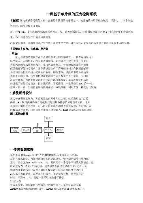
2系统硬件设计压力传感器测量压力,并将测量的信号输入放大器,然后送至A/D转换器,A/D转换器将输入的模拟信号转换为数宇信号送至单片机。
单片机依照已编制好的程序,对压阻元件非线性测量误差进行修正并对修正后的数据进行处置。
同时该系统兼具有键盘输入,LED显示与超限报警功能。
图1系统结构图21传感器的选择采纳美国ICSensors公司生产的ICSl220低压型硅压力传感器。
双列直插式封装,内部桥路由外部恒流源供电,输出毫伏信号与压力成正比,线性度为0.05%一o.1%。
其内部有一个用于平稳放大器增益、温度系数为20*10-6/℃的电阻,使传感器互换误差操纵在1%之内。
传感器内部电路尽管已设置了温度补偿方法,但当环境温度在25℃4-25℃范围内转变时,温度漂移仍较大,按满量程计算,量程漂移为03%,零漂0.1%,需进一步采取方法进行补偿。
- 1、下载文档前请自行甄别文档内容的完整性,平台不提供额外的编辑、内容补充、找答案等附加服务。
- 2、"仅部分预览"的文档,不可在线预览部分如存在完整性等问题,可反馈申请退款(可完整预览的文档不适用该条件!)。
- 3、如文档侵犯您的权益,请联系客服反馈,我们会尽快为您处理(人工客服工作时间:9:00-18:30)。
一个完全植入式无线压力监测系统的开发摘要:一个完全植入式无线压力传感器监测系统的开发是为了检测体内膀胱的压力。
该系统包括一个小型的商业压力模具经导管连接到电子放大设备,一个微控制器,无线发射器,电池和个人数字助理(PDA)或接收无线数据的计算机。
该传感器是完全植入的,并且每秒传送一次压力数据,压力检测评估范围为1.5 psi,分辨率为0.02 psi。
在体外,设备的校准测量表现出高度的线性度和良好的时间响应。
该装置植入一些猪的体内进行研究,历时超过3天。
该系统能适用于其他方面的压力读数,以及其他生命体征的测量,它迈出了一个无处不在的发展远程医疗和远程病人监控平台的第一步。
关键词:微机电系统、压力传感器、植入、患者的监测、遥测、远程医疗、膀胱、无线1介绍:目前,医学界对在家和在医院的病人的远程医疗和远程监控产生了浓厚的兴趣。
当前,病人监护仪器和实现手法是繁琐和局限的。
例如,在重症监护病房,血压监测可用动脉线进行连续监测。
这是一个放置在动脉的导管,并且外部传感器能检测到压力。
它的局限性是高度可变的准确性,患者往往服用镇静剂,以防止因运动对自身造成伤害。
另一方面,在标准的基础护理中,虽然对病人是完全非侵入性,并且免除了他们的负担,但是,病人血压标准测量与非连续点的测量通常采取每2-12小时一次。
重要的生命体征测量值间的显影可能被错过。
目前,还没有连续监测生命体征的,并且可提供无极端入侵和或麻烦的,如同临床医生的设备。
一个连续的,能够实时检测的,并且监测没有显著减少病人的舒适或限制其自身的运动的设备将在性能和舒适的集约化和标准治疗上缩小差距。
一个简单而划算的的解决办法是利用无线遥控可植入微系统。
无线遥测技术释放了被束缚的患者,使他们脱离了大医院的监控,他们可以参加医院无线传感器网络,该网络通过最大限度地减少人员的工作负荷,增加获得的数据量,并简化其存储和处理,进而可能会提升监控效率。
在大多数情况下,无线植入式压力传感器发展的重点是由无线电供电设备射频(RF)感应,使无限期植入和手术操作时没有必要交换电池。
此外,设备总体积最小化,因为电池通常是最大的组成部分。
一些团体已经开发和测试出能够检测股动脉动态血压或动物模型主动脉的设备(纳杰菲和Ludomirsky2004;Schlierf等。
2007年)。
然而,传输范围通常局限于厘米(纳杰菲和Ludomirsky2004;Schlierf等。
2007)和传感器射频感应时只能传输数据。
这往往限制了离散时间点的测量或在病人身上装上天线在所有的时间连续测量(CardioMEMS2007;沃尔顿和克鲁姆2005年)。
这里,我们提出了一个不同的方法来监测流动压力,其中包括:微压模具,电子放大器,微控制器,无线发射器,电池,和通讯的个人数字助理(PDA)或计算机。
2方法和材料:压力传感平台分为三个部分:压力传感导管导线;传感器节点(图1);PDA或电脑接收器。
以上各部分的制造将在下面部分讨论:2.1导管导线:该导管导线装载了压力传感器,并且连接到传感器节点上(图2)。
它由一个用紫外线环氧树脂(Masterbond UV10)印刷在测量0.65×0.65毫米的陶瓷印刷电路板(PCB)的压阻压力传感器(硅微5108)构成。
模具设计参考了它的大小,感应距离,精确度,灵敏度具有1.6 mV/ psi的音频/视频。
芯片上的应变片配置在温度补偿的惠斯登电桥。
然后,该芯片(西邦德7402C)焊接到基板焊盘上。
四个单独绝缘铂铱(铂铱),通过一个7.5French(2.5毫米)的电线焊接到连接到接触焊盘的电路板。
紫外线环氧树脂应用于基板焊盘和芯片上,并进行8分钟固化,以防止任何铂铱电线或wirebonds破坏连接。
有四个楔形孔金帽削减了紫外线对环氧树脂印刷电路板压贴的压紧膜,以保护芯片。
四铂铱线被缠绕在一个高强度聚酯绝缘的磁芯,并通过聚乙烯管材。
该装配用硅胶填充焊接螺纹管。
图1图1:在设备充分植入并充分包装后,该压力传感器安置在7.5French的导管中,它直接植入膀胱或腹腔。
导管的另一端连接到传感器节点,这些点由单片机和无线发射器,电子产品放大器和电池组成。
该设备是包裹在LDPE薄膜上并用医用级硅橡胶制造成型。
图2图2:艺术家的设计引领导管导线技术的尖端。
(a)给出了无包装的领先技术,商业压紧膜焊接到PCB板上。
四铂铱通过导管电线焊接到PCB板上。
(b)描绘了包装的领先技术。
金盖板,保护芯片和丝焊。
缠铅玻璃纸; PDMS 塑造其周围,以增加生物的相容性。
2.2传感器节点:该传感器节点由三个部分组成:电子放大器,微控制器和无线发射器,电池。
导管导线的一端焊接到一个特定的电路板上。
这个电路板是四元组微功耗,单电源运算放大器(德州仪器TLV2764),一个2.5伏的电压调节器芯片(模拟装置REF192)和一个单刀双掷(SPDT)磁簧开关打开和关闭设备(哈姆林)(林2007)。
芯片组的电压调节器的电源电压供电的设备和其他电子产品电压设置到2.5 V。
以防止因电池电压的变化引起压紧膜信号的变化。
运算放大器被配置为无任何偏移量将传感器电压从放大桥放大到300倍。
生理相关的压力测量范围为1.5 psi的表压,并与器件的灵敏度,电源电压和放大器,设备输出为1.2伏/ psi和生理压力范围为1.8V。
该放大电路的输出被连接到微控制器和无线发射器(Mica2Dot(Crossbow MPR510CA),以下简称为the dot mote),其中发射功率为433兆赫。
我们编程的微控制器以获取和传输数据,同时最大限度地提高电池的寿命在以下三个方面:首先,微控制器使传感器的测量脉冲周期为30微妙,在这之后整个设备进入睡眠模式。
第二,测量时只有每秒一次。
最后,由于传输消耗最大电量,采样的数据存储在本地the dot mote中,并且每测量30次传输一次(林等人。
2007)。
这些技术是能量消耗从3兆焦耳降到625μJ(林2007年,林等人2007年)。
电池使用的是3.7伏,850毫安时锂聚合物电池(电池美国)。
该装置的使用寿命是387300次测量,或者在电池电压低于电源电压情况下,大于四天采样率不变。
一旦组装完成,传感器节点包裹25微米厚的低密度聚乙烯(LDPE,塑料薄板供应)和压缩,再PDMS成型。
此后,该装置浸入聚二甲基硅氧烷的第二硅层,以堵塞第一层硅橡胶的任何漏洞。
期间和之后的包装过程中,电池无法充电或更换,所以是钕磁铁被堆放在模具上并激活磁性开关和在它24小时治愈后关闭设备。
2.3无线通信:该点配有互补的通信接收机基站(Crossbow MIB510CA),该基站连接到计算机。
发送的dot mote是十六进制格式的,其中包括一个时间戳,一个独特的ID标签,剩余的电池电压,放大的压力数据。
LabVIEW的(美国国家仪器公司)的程序来读取和转换成数据包,该数据包保存在一个文本文件中,并能实时绘制图形曲线。
2.4体外试验:一旦一个导管导线制作完成,每根导线都要进行单独测试,并且将其放置在密封压力腔中测试其性能,这是通过压力腔盖电连接到电线上。
导线外部供电(安捷伦E3630A)和高精度万用表测试输出电压(吉时利2000年)。
压力是在大气压力恒定下举行了30分钟,而生物医学Microdevices的(2009)NISTcalibrated压力表(欧米茄DPG5600B-30A)11:259-264261器件的输出和压力读数每5分钟记录一次。
体腔连接到了一个压缩的氮气瓶,通过压力调节器将压力上升到1.0 或1.5 psi并保持三十分钟。
对于第一个十分钟,压力和电压读数被全部带走,在后来的二十分钟,每五分钟检测一次。
压力容器释放出大气压力和电压,前十分钟,压力彻底读出,在后来的二十分钟,每五分钟读取一次。
每根导线校准三次,以测试环境对导线及其包装的影响。
他在空中检测,首先作为一个控件,然后导线的尖端放置在容器的烧杯的水中,开始测试之后,让它在水下保持四天。
如果四天后输出的量值和时间响应和以前一样,这就搭配了一个传感器节点。
经过一个传感器节点配对的导管导线,整个装置进行了包装前的再次测试。
导线被放置在密封的水压力容器。
该传感器节点连接到连接外部压力腔的导线,并有电池或者DC电源供电。
LabVIEW计算机程序运算和存储无线压力数据。
压力是从0-1.5psi逐步加大以测试实验所需压力范围,每步保持五分钟,每两分钟进行一次压力读数。
为了检验该设备分辨率,增量为0.02 psi的压力变化从0到0.1psi和0.1psi的增量从0.1到1.5psi。
在每次试验结束后,标准曲线生成相关的电压数值通过电脑记录到压力腔内。
另一个测试封装设备是将它淹没 2.5 gal 染色的水中并传输数据,直到电池耗尽。
之后进行数据分析,以寻找任何短路的迹象,描绘任何传感器漂移现象和量化设备的全寿命。
包装后来被去除,看是否有漏水的痕迹。
2.5 体内测试:经加州大学洛杉矶分校医学中心IRB # 2004年-185-11批准,成年母猪被用于作为体内测试。
一个设备植入膀胱,另一个放置腹腔内作为参考。
当传感器节点被放置在皮下组织中时,导管的导线被放在那些场所。
手术后,猪被关在动物园的围栏中,从而使在围栏外的计算机和设置好的无线电接收器收集数据。
在这种情况下,猪都有充分的意识到和动态。
在接下来的2-4 天,猪被处死,然后分离出设备。
简单进行尸检,以寻找组织炎症或任何免疫反应的有机硅包装。
然后检查设备是否有任何损坏,泄漏或如有必要的话,再寻找任何其它故障点。
3结果及讨论:组装完毕的铅导线和传感器节点的测试显示了传感器的快速线性响应(1.34 psi/V)。
在初次测试之后,对设备进行拆卸和重新组装。
观察到偏移量略有改变。
一旦该设备完全包装和准备植入,这种变化通过计算的压力校准的比较曲线和压力表的实际压力和调整校准曲线的偏移值进行补偿。
在测试聚二甲基硅氧烷包装的完整性时,设备在不失灵的情况下运作,直到电池设备使用107 h而耗尽。
在前两天半时间内,输出的电压变化小于0.0003。
然而,在接下来的 2 天,电压稳步下降直至设备停止运作。
一旦停止运作,设备就检测出无液态水或气态水,或水的PDMS渗透层,这样,数据就不会因短路丢失了。
4结论:总之,我们已建立了完全植入体内的无线压力传感器,其在短期内应用于泌尿系统的研究和病人监护仪上。
体外测试演示其快速的时间响应和其高线性。
通过膀胱和猪腹腔模型的体内试验,压力传感系统能够成功记录医学相关的数据,其中包含像排尿这种生理活动。
这个平台可以扩展其他的传感模式,如测核心温度的热敏电阻,白金和银电极测血液或组织氧气电压,铅植入动脉以获得心率血压分析参数。
导管进一步小型化到点,这样,它能放入针中,进而可以消除人体对大手术的需要。