
t.c.electronic M-One XL 快速操作指南
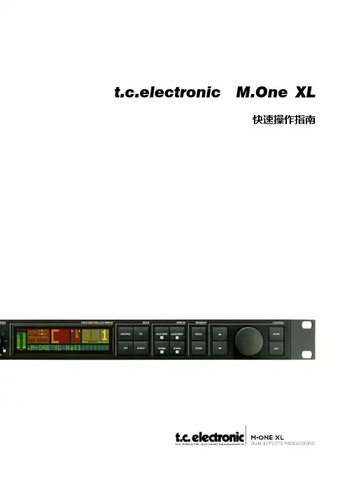
t.c.electronic M.One XL快速操作指南一.前面板相关英文的解释1.POWER ‐ 电源开关2.LEVELS ‐ 电平IN LEVEL ‐ 输入电平:主要调节调音台输出至效果器的电平,在显示屏上有数字电平峰值表,当输入信号过大,超过0dB时,红灯亮起,发生声压级过载现象。
MIX ‐ 混合比:当调至极左的时候为干声,此时无效果,当调至极右的时候为最大比例的湿声效果(混合比例为100%)。
EFFECT BAL ‐ 效果平衡:调节引擎1(如:延时效果)和引擎2(如:混响效果)效果平衡作用,当调至12点位置的时候两个引擎效果电平相等。
3.SETUP ‐ 设置ROUTING ‐ 路径:设置引擎的路径分配。
选项有:DUAL S/R(双发送/返回)、PARALLEL(并行,左右声道混合输入输出)、PAR/SER(并行/串行)、SERIAL(串行)、STEREO‐LINKED(连锁立体声)、DUAL MONO (双单声道)。
I/O ‐ 输入/输出:设定输入输出的基本参数 。
包含有Input(输入信号的选择)、Clock(时钟,用来选择输入信号的采样频率)、Out Range(输出范围)、Out Level(输出电平)、Dig In Gain(设置数字输入电平,只影响数字输入信号)、Dither(高频颤抖噪声,只与数字输出有关)。
TAP – 节拍键:此键可根据音乐的节拍设定延时效果。
Tap Time(延时时间,可用转轮改变延时时间,也可根据音乐的节奏双击TAP键改变延时时间)、Tap SubDiv(细分节拍,细分由M.ONE如何响应敲击的速度来决定) 、Tap Func(节拍功能,设定节拍控制对哪个引擎有效)、MIDI Sync(MIDI 同步)。
UTILITY 实用设置:设置本机的MIDI、系统专用ID、路径锁定、直通方式、踏板功能和显示视图方式等参数。
4.EFFECTS ‐ 效果ALGO/EDIT 1+2:按下此键确定编辑显示和当前所选引擎的效果变化显示。
BYPASS ‐ 效果旁路键:可以在Utility(实用设置)中设置直通方式。
有三种不同的直通方式:z0%混合 ‐ 输入信号直接输出。
z FX 输入 ‐ 为了使效果“振铃淡出”,将只衰减引擎的输入,但是输入的同样量的干信号会留下来。
z FX 输出 ‐ 为了能快速削减掉FX。
将只衰减引擎的输出,但是输入的同等量的干信号会留下来。
5.PROGRAM ‐ 程序RECALL ‐ 调用:选择Recall(调用)菜单。
用控制轮选择一个想要的预置,并按下ENTER 键来确认装载所选预置。
STORE ‐ 存储:选择存储菜单。
预置可以只被存入用户库。
用CONTROL(控制)轮选中位置,再用ENTER 确定操作。
6.CONTROL ‐ 控制上/下箭头:用来选择每个按键中修改的项目。
ENTER键:确认操作。
当可以使用此键时,ENTER 键的灯会有所指示。
EXIT 键:用于退出一个菜单或否定一个动作。
CONTROL轮:用于修改数值。
二.有关t.c.electronic M.One XL 的6种路径1.DUAL S/R ‐ 双发送/返回:此路径适用于将设备 作为两个独立的效果处理器使用。
左边的输入送至引擎1,右边的输入送至引擎2。
四个FX 输出合成两个通道输出。
2.Parallel ‐ 并行,左右声道混合输入输出:并行路径拥有左/右输入,送至两个引擎的信号是完全相同的。
通过Mix 参数可以将未经处理的干信号与处理过的信号混合,送至两个通道。
3.PAR/SER ‐ 并行/串行:对于双声道输入路径,并行-串行路径分配是一样的,除了一个:引擎1的输出可以被送回给引擎2的输入。
这可以是用户将混响加至延时后的反复上。
加至引擎2上的信号量可以由引擎2的交叉馈送(Crossfeed)参数控制。
引擎2的Crossfeed 参数可以在路径分配菜单中找到,它是预置的一部分。
4.SERIAL ‐ 串行:在串行方式下信号总是在通过引擎2之前通过引擎1。
串行路径下,MIX 旋钮的功能与引擎1的Mix 控制一样。
例子:引擎1选择咝声消除器,引擎2选择一个明亮的混响。
此时咝声消除器将抑制人声中的“Sss”声,操作者可以使用明亮而开放的混响,同时不用担心会有太多的咝声。
5.STEREO LINKED ‐ 连锁立体声:在连锁立体声路径分配方式下,使用同步的参数设置,引擎会有完全相同的效果。
左I/O被用于引擎1,右I/O 被用于引擎2。
打开连锁立体声路径分配后,引擎1的设置会强加给引擎2。
6.Dual Mono ‐ 双单声道:在双单声道路径分配下,两个引擎都是独立的,也就是每个引擎的MONO IN(单声道输入)/MONO OUT(单声道输出)都独立。
左I/O用于引擎1,右I/O 用于引擎2。
三.简易操作1.按I/O键选择模拟信号为例¾出现INPUT,设置输入信号:模拟或者数字格式。
由转轮控制改变。
¾按下箭头可看到CLOCK字样,用转轮来选择采样频率。
输入为模拟信号时:z在Out Range中设置限制输出信号的最大动态范围,用转轮来选择。
推荐参量14dBu。
z在Out Level中设置输出电平,用转轮来选择。
通常设为0dBu。
输入为数字信号时:z在Dig In Gain中改变数字信号的输入电平。
z在Dither中设置高频颤动比特数。
2.按下ROUTING 键,进入路径显示。
用CONTROL ENTER键开始闪。
按下ENTER。
在选择UTILITY ON,把路径锁住。
3.给引擎1.2设定效果a)先选择ALGO︱EDIT键,切换至屏幕显示为FX1的参数菜单,然后转动数据轮,观察屏幕,调整至两通道都为1号效果,也就是HALL REVERB(大厅混响)效果后。
按ENTER键确定。
b)按ALGO|EDIT2,切换至屏幕显示为FX2的参数菜单,调整数据轮,选择ONE‐Tap Delay(延时)效果。
然后按ENTER键确定。
c)在两个引擎中,可分别选择ALGO|EDIT1和ALGO|EDIT2键,可切换成屏幕显示为Decay(第一个引擎)和Delay time(第二个引擎)的菜单,此时通过按上下箭头键,可调整其它效果参数。
下面是做为卡拉OK效果调整的参数,可做参考。
HALL REVERB参数:Decay: 2.6S Pre delay: 23ms Size: LargeHigh cut: 20KHz Hi Color: 6 Lo Color: 6Reflect Lev: 0dB Reverb Lev: -6dB Mod Type:smoothMod Depth:25 Mod speed: 7 Fx Level: 100%ONE‐Tap Delay参数:Delay time: 240ms Feed back: 25% Pan: Center High cut: 20KHz Low cut: 79.43Hz Fx Level: 100%4.调用一个预置按下RECALL键,进入RECALL 菜单。
用CONTROL 轮预览预置。
预览方式由闪烁的预置号和ENTER 键 上闪烁的LED 指示的。
按下ENTER 或RECALL 调用/启动预置。
在预览时按下EXIT 键可以回到当前调用的预置。
PRESET TYPES‐ 预置类型用户预置-RAM:用户预置可以编辑并存储在任何用户区域。
用户库中最多只能存100个预置。
厂家预置-ROM:厂家预置可以在任何用户区域编辑和存储。
200个厂家预置。
5.存储基本操作a)按下STORE 键进入存储页面。
ENTER 键和预置号将开始闪烁,以指示当前预置还没有被存储。
Preset Locations ‐ 预置区域预置只能被存在用户区域。
除非当前调用预置是一个用户预置,否则存储页面将自动认定存储器中第一个空的用户区域为存储空间。
在此情况下,同一个用户区域将被认定。
b)以同样的名称在同一区域存一个以编辑预置,按下STORE 键进入存储菜单。
按下ENTER 键存储。
显示屏上快速闪过“Stored(已存)”,然后回到调用页面。
以同样的名称在不同区域存一个预置按下STORE 键进入存储菜单。
用CONTROL 轮选择存储区域。
按一下ENTER 存储预置,显示屏上快速闪过“Stored(已存)”,然后回到调用页面。
c)以一个新名称存一个预置。
按下STORE 键进入存储菜单。
用CONTROL 选择存储区域。
在按一下STORE 键或ARROW DOWN键进入“NAMING(命名)”显示。
用ARROW键修改游标位置。
转动CONTROL 轮选择字母。
按下ENTER 键存储预置。
四.M.One XL在多功能厅中作为人声效果器使用的调试方法1.路径选择:当使用M.One XL的时候,要先进行路径分配,可选择DUAL S/R(双路送出/返回)路径。
2.将前面板的INPUT(输入电平)调整至12点位置也就是0dB3.将前面板的MIX(干/湿声音混合比例旋扭)调整至极右位置,这样可获得一个丰满不失真的效果。
4.将前面板的EFFECT BALANCE(多重效果/混响效果平衡旋钮)调整至12点位置这样两个引擎的效果的混合比例是等同的。
5.给引擎1添加Delay的效果,给引擎2 添加大厅混响的效果。
具体的效果各参数可根据实际情况进行调整。
五.M.One XL在卡拉OK厅中作为人声效果器使用的调试方法1.路径选择:当使用M.One XL的时候,要先进行路径分配,可选择Parallel(并行)路径。
2.将前面板的INPUT(输入电平)调整至12点位置也就是0dB3.将前面板的MIX(干/湿声音混合比例旋扭)调整至极右位置,这样可获得一个丰满不失真的效果。
4.将前面板的EFFECT BALANCE(多重效果/混响效果平衡旋钮)调整至12点位置这样两个引擎的效果的混合比例是等同的。
5.给引擎1添加Delay的效果,给引擎2 添加大厅混响的效果。
具体的效果各参数可根据实际情况进行调整。
TC M1XL效果器使用说明书

双效果处理器
用户手册
重要安全说明
TYPE P210
TYPETYP
CAUTION
CAUTION WARNING
TO REDUCE THE RISK OF FIRE OR ELECTRIC SHOCK DO NOT EXPOSE THIS EQUIPMENT TO
WARNING200-240V~ TSOHORCEKDDUOCENOTHT EEXRPISOKSEOTFHFISIR5EEQ0OU-RI6PEM0LHEENzCTTTR1OI.C8W
绝险缘。“危险电压”,可能形成触电的危 在重要的操作和维护(服务)说明。 TCCOHAOPINEMSARPCDALLITIAAEIONSSSNIWNBSITTUDEHBRIGJPFEIAETCRARTTLETND1O5CEVEOCI-FOCCNETAHDUMEISTEIIFNEOCTGNCSSERAQSLUUTLLAIPERTCCOTMSEHEAOP.QEDINEMSNUARIPCNTIDARLLRTITIEAAEIHEMONSSGESNEWIUNMNBSILTTTAUADESHNBTRIGUOJIPFOEIAFAETNCLRARTS.TTLHEATNED1ON5CEDVEOCI-FOCCNETAHDUMEISTEIIFNEOCTGNCSSERAQSLUUTLLAIPERTMSEE.QEDNUINTIRRTEHEMGEEUMNLTAASNTUOIOAFNLTS.HAEND
式插头有两个刃片和一个接地极。极化插头 XPOSE THIS EQUIPMENT TO RAIN ORDOMONOISTTUERXPEO. SE THIS EQUIPMENT TO RAIN OR MOISTURE.
ALIENWARE M11x MOBILE手册说明书

注、小心和告
注:“注”表示帮助您更好地使用计算机的重要信息。 小心:“小心”表示潜在的硬件损坏或数据丢失并告诉您如何避免此类问题。
警告:“警告”表示潜在的资产损坏、人身伤害或死亡。
__________________ 此处内容如有更改,恕不另行通知。 © 2011 Dell Inc. 保留所有权利。 未经 Dell Inc. 事先书面许可,严禁以任何方式复制这些材料。 本手册中使用的商标:Alienware®、AlienFX® 以及 AlienHead 徽标是 Alienware Corporation 的商标或注册商 标;Dell™是 Dell Inc.的商标;Microsoft®、Windows® 和 Windows 开始按钮徽标 是 Microsoft Corporation 在 美国和/或其他国家或地区的商标或注册商标;Intel® 以及 SpeedStep® 是 Intel Corporation 在美国和其他国家 或地区的注册商标,Core™是 Intel Corporation 在美国和其他国家或地区的商标;Blu‑ray Disc™是 Blu‑ray Disc Association 的商标;Bluetooth® 是 Bluetooth SIG, Inc. 拥有的注册商标。 本手册中所述及的其它商标和商品名称是指拥有相应商标和商品名称的公司或其产品。Dell Inc. 对不属于自己的商 标和商品名称不拥有任何所有权。 管制型号:P06T 管制类型:P06T003 Rev. A01 2011 - 05
3
目錄
第 3 章:使用膝上型计算机 . . . . . . . . . . . . . . . . . . . . . . . . . . . . . . . . . . . . . . . . . . . . . . . . . . . . . . . . . . . 37 Alienware 命令中心 . . . . . . . . . . . . . . . . . . . . . . . . . . . . . . . . . . . . . . . . . . . . . . . . . . . . . . . . . . . . . . 38 FastAccess 人脸识别(可选) . . . . . . . . . . . . . . . . . . . . . . . . . . . . . . . . . . . . . . . . . . . . . . . . . . . . . 42 电池组 . . . . . . . . . . . . . . . . . . . . . . . . . . . . . . . . . . . . . . . . . . . . . . . . . . . . . . . . . . . . . . . . . . . . . . . . . . . 42 使用无线控制功能 . . . . . . . . . . . . . . . . . . . . . . . . . . . . . . . . . . . . . . . . . . . . . . . . . . . . . . . . . . . . . . . . 44 电源管理 . . . . . . . . . . . . . . . . . . . . . . . . . . . . . . . . . . . . . . . . . . . . . . . . . . . . . . . . . . . . . . . . . . . . . . . . . 45 NVIDIA Optimus 技术 . . . . . . . . . . . . . . . . . . . . . . . . . . . . . . . . . . . . . . . . . . . . . . . . . . . . . . . . . . . . . 47 配置 BIOS . . . . . . . . . . . . . . . . . . . . . . . . . . . . . . . . . . . . . . . . . . . . . . . . . . . . . . . . . . . . . . . . . . . . . . . . 49
t.c.electronic M-One XL 快速操作指南
t.c.electronic M.One XL快速操作指南一.前面板相关英文的解释1.POWER ‐ 电源开关2.LEVELS ‐ 电平IN LEVEL ‐ 输入电平:主要调节调音台输出至效果器的电平,在显示屏上有数字电平峰值表,当输入信号过大,超过0dB时,红灯亮起,发生声压级过载现象。
MIX ‐ 混合比:当调至极左的时候为干声,此时无效果,当调至极右的时候为最大比例的湿声效果(混合比例为100%)。
EFFECT BAL ‐ 效果平衡:调节引擎1(如:延时效果)和引擎2(如:混响效果)效果平衡作用,当调至12点位置的时候两个引擎效果电平相等。
3.SETUP ‐ 设置ROUTING ‐ 路径:设置引擎的路径分配。
选项有:DUAL S/R(双发送/返回)、PARALLEL(并行,左右声道混合输入输出)、PAR/SER(并行/串行)、SERIAL(串行)、STEREO‐LINKED(连锁立体声)、DUAL MONO (双单声道)。
I/O ‐ 输入/输出:设定输入输出的基本参数 。
包含有Input(输入信号的选择)、Clock(时钟,用来选择输入信号的采样频率)、Out Range(输出范围)、Out Level(输出电平)、Dig In Gain(设置数字输入电平,只影响数字输入信号)、Dither(高频颤抖噪声,只与数字输出有关)。
TAP – 节拍键:此键可根据音乐的节拍设定延时效果。
Tap Time(延时时间,可用转轮改变延时时间,也可根据音乐的节奏双击TAP键改变延时时间)、Tap SubDiv(细分节拍,细分由M.ONE如何响应敲击的速度来决定) 、Tap Func(节拍功能,设定节拍控制对哪个引擎有效)、MIDI Sync(MIDI 同步)。
UTILITY 实用设置:设置本机的MIDI、系统专用ID、路径锁定、直通方式、踏板功能和显示视图方式等参数。
4.EFFECTS ‐ 效果ALGO/EDIT 1+2:按下此键确定编辑显示和当前所选引擎的效果变化显示。
恩临公司EDI操作运行手册XL400
ELEDI超纯水一体机操作运行手册恩临科技恩临科技保留任何时间修改该产品技术规格的权利,如有修改,恕不另行通知。
详情访问EDI专业服务网站说明感谢您成为恩临科技产品的用户! 在使用前请详细阅读本手册及模块相关电子文件, 并始终遵守本手册及模块相关电子文件有关规定.请保存此书以备日后参考.恩临科技保留不断改进产品的权利,如有变动恕不另行通知.ELXL400-1的ELEDI 纯水处理系统Electropure EDI概述采用Electropure公司的专利产品--电去离子设备(EDI设备)可以满足日益增长的对高纯水的需求。
Electropure从前的HOH水技术公司,在20世纪80年代一直是EDI技术的带头人。
发布于1984年的O’Hare 专利奠定了EDI技术的基础。
EDI工艺系统代替传统的DI混合树脂床来制造去离子水。
与DI树脂不同的是,EDI 在更换树脂床或使用化学试剂进行树脂再生时并不需要关闭系统。
正因为如此,EDI 具有:水质不稳定因素减少到最少最少的运行成本EDI主要是从与反渗透(RO)及其它纯化设备处理过的水中去除离子。
我们的高质量模块可以连续产生高达18.2MΩ.cm的超纯水。
EDI可以连续运行或者间歇运行。
比传统离子交换DI优越之处EDI不需要酸碱化学试剂用于再生(就像离子交换系统DI的树脂再生)EDI再生时不需要关闭设备Electropure EDI模块在市场上每单位流量中最小、最轻,因此EDI趋于紧凑产品水水质稳定一致所需能源少资金的使用经济—节约了运行费用电去离子(EDI)工艺Electropure EDI的设计包括了两个成熟的水净化技术—电渗析和离子交换树脂除盐。
通过这种革命性的技术,用较低的能源成本就能去除溶解盐,而且不需要化学再生;它能产生好几个兆欧(MΩ·cm)电阻率的高质量纯水,且能够连续稳定大流量的生产。
Electropure EDI通过一个电势迫使离子从进水流中分离出来,再进入与进水流毗连的水流中。
t.c.electronic MOne XL 快速操作指南概要
t.c.electronic MOne XL 快速操作指南概要简介t.c.electronic MOne XL 是一款高品质的数字音频处理器,具有多种效果和功能,能够帮助您在音乐制作和演出过程中实现出色的音效。
本快速操作指南将向您介绍MOne XL的基本功能和操作方法,帮助您快速上手使用这款强大的音频处理器。
主要特点MOne XL具有以下主要特点:1.24位AD/DA转换器,提供高质量的音频处理。
2.25种内置效果算法,包括混响、调制、延迟等,可用于各种音频处理需求。
3.简单直观的操作界面,方便快速调节和编辑音效参数。
4.可通过MIDI控制器或计算机进行远程控制。
5.多种输入和输出选项,满足不同音频设备的连接需求。
快速设置接下来,我们将向您展示如何快速设置并开始使用MOne XL。
1.首先,将MOne XL连接到音频设备。
您可以选择使用MOne XL的模拟输入和输出,或者通过数字接口连接到计算机或音频接口设备。
2.打开MOne XL的电源,并确保音频设备的输入和输出设置正确。
3.现在您可以开始调节MOne XL的参数了。
参数调节MOne XL提供了多种参数调节选项,以满足您的音频处理需求。
下面是一些常用的参数调节方法:1. 选择音频效果MOne XL内置了25种音频效果算法,您可以通过旋钮或按键来选择所需的效果。
例如,按下“Reverb”按钮可以选择混响效果。
2. 调节效果参数一旦选择了所需的音频效果,您可以通过旋钮或菜单来调节不同的参数。
例如,您可以使用旋钮来调节混响的深度、尺寸和混合度等参数。
3. 存储和召回预设MOne XL还提供了存储和召回预设的功能。
通过按下“Store”按钮,您可以将当前的参数设置保存为一个预设。
而通过按下“Recall”按钮,您可以从预设库中召回已保存的预设。
4. 远程控制如果您希望通过MIDI控制器或计算机远程控制MOne XL,您可以将其与相应的设备进行连接,并在MOne XL菜单中选择相应的远程控制模式。
Xrite-DTP70和Epson XL 10000XL扫描仪的使用说明说明书

How to use Xrite and Epson ScannerByungseok MinMehul JainElectronic Imaging Systems LaboratorySchool of Electrical EngineeringPurdue UniversityTable of ContentPg. No.Overview 3Chapter 1: Managing X-rite1.1 Software Location 51.2 Designing Test Patterns 5 - 10 1.3 Modifying Test Patterns 11 - 13 1.4 Measuring Test Patterns 14 – 15 1.5 Exercise examples 16 - 18Chapter 2: Managing Scanner2.1 Scanner Details 192.2 Screenshots 20 - 25 2.3 Scanning Procedure 26 - 28OverviewScanner calibration is the process to estimate CIE XYZ values of the printed image from the device dependent RGB values of the scanned image.Spectro-photometer and scanner are used to obtain CIE XYZ value and to scan the image. It is essential to know how to use the devices to obtain correct data.This manual consists as follows.First, it will describe how to use Xrite-DTP70 to measure CIE XYZ values of hardcopy. And then it will describe how to use Epson XL 10000XL scanner with the option we have to choose.The other parts consist of gray balancing and regression model to explain the analytical scanner calibration model.CHAPTER 1 Managing X-rite1.1 Software LocationThe software used to manage X-rite is ‘Colorport 1.0.1’ and can be found in‘C:\Program Files\X-Rite\ColorPort\ColorPort’1.2 Designing Test Patterns in Colorport:Though the X-rite comes with a variety of test patterns, it might be best to design a different one for application in research work. Following steps should be followed while designing a test pattern.unch X-rite by running ‘C:\Program Files\X-rite\ColorPort\ColorPort’2.Select X-Rite DTP 70 from the ‘Measurement Device’ menu. Select CMYKin the color space and select the appropriate paper size and format.Figure 1 shows a screenshot of the application with the above mentionedsettings selected.Figure 1 : Screenshot showing initial settings.3. Select ‘New’ from the Patch Set menu. A window opens up as shown in Figure2.Figure 2 : Screenshot showing window that opens up after New is selected.4. Press ‘+’ sign repeatedly to get desired number of patches. A CMYK value can be given to each of the patches individually, this is optional. If left blank, a value of zero is assumed automatically. Give a name with which the pattern should be saved. Click on ‘Save’ once done with adding patches. Figure 3 shows a screen shot of ‘Customize’ window with 100 patches.5. Once ‘Save’ is pressed, the customization window disappears and the original window shows a preview of how the test pattern looks like. As mentioned earlier, the color of patches is irrelevant and only helps in depicting the visualization of test pattern. To make the designed test pattern match the requirements a few specifications can be customized.6. Click on ‘Properties’ button placed below ‘Measurement Device’. A window opens up as shown in Figure 4. ‘Patch Width’ and ‘Patch Height’ can be altered from 6 mm to 20 mm. These values can be changed to accommodate more or less test patches in a row. The header and trailer length can be altered toincrease/decrease the distance between the test patches and top and bottom red line. Figure 3 : Screenshot showing customization window7. Selecting ‘OK’ closes the properties window and updates the preview window with the change in settings.8. Click on ‘Margins’ in next to the ‘Paper Size’ section in the main window tochange the page margins. This will again give the freedom to increase / decrease the number of test patches in one row. Also, either of ‘Portrait’ and ‘Landscape’ formats can be selected to meet the requirements for the test patch.9. Test patches can be added/ deleted/modified anytime by clicking on ‘Customize’ under the ‘Patch Set’ column.Figure 4 : Screenshot showing Properties window10. Once satisfied with the test pattern, click on ‘Save Target’ and save it as a tiff file in a preferred location.11. There are further possibilities of fine tuning the test pattern. See the next section for more details.Figure 5 shows a test pattern designed using Colorport software.Figure 5: Test Pattern designed using ColorportIt should be noted that the black patches in the first and the last column represent a grid which X-rite uses to approximate the start and the end point. The test pattern above has 12 rows and 28 columns that makes the total number of test patches to be 336.When a test pattern is created using Colorport, several files are generated. One is ‘.tif’ file which is an image representation of the test pattern designed. A ‘.xml’ file is generated which contains all the information about the designed test pattern and can be used for importing and exporting test patterns. ‘.tab’ file is also generated and it contains information about the individual test patches in a test pattern. This file can be used to modify the total number of test patches etc.1.3 Modifying Existing Test Patterns:If a test pattern already exists, it can be modified in two different ways depending on the format of the file of the test pattern.1.3.1 .xml fileIf the test pattern exists in form of a .xml file, then changes can be made to the xml file to meet the requirements. The .xml file contains detailed information about specifications of the test patterns that would be used by X-rite formeasurement purposes. Figure 6 shows a sample .xml file for one of the testpatterns created using Colorport.Figure 6: screenshot showing sample .xml fileAs is clear from Figure 6 above, the .xml file contains information such as patch width, height, page width and height, page margins, etc. These values can be changed individually to meet the requirements. Unfortunately, there is no method of viewing the effects of changes made to .xml file. So, a trial and error method needs to be adopted to make the .xml file work for the test patterns in hand. Once the changes have been made, the file should be saved againas .xml file and imported into Colorport. Steps to Import the file are listed below.Importing/Exporting .xml fileFrom the file menu in Colorport, select ‘Target Manager’. A window opens up as shown in Figure 7. Click on ‘import’ and then give the location of .xml file. Same procedure can be followed for exporting a .xml file.Figure 7: screenshot showing ‘Target Manager’ window1.3.2 .tab file.tab file can be used to import individual test patches within a test pattern to create a new test pattern. To import test patches from a .tab file, follow the following steps:1. Open the .tab file in notepad and save it in .txt format.2. Make sure that the correct color space ( RGB / CMYK etc.) is selected in the menu under ‘Color Space’ column.3. Select ‘New’ from the menu in ‘Patch Set’ column.4. Click on ‘Import Patches’ button in the window that opens up. Figure 8 shows the results of importing test patches.Figure 8: screenshot showing import of test patches from .tab file5. Once the patches have been imported, relevant steps mentioned in section 1.2 can be followed to modify the test pattern as needed.1.4 Measuring Test PatternsOnce the test pattern has been created / modified using any of the steps mentioned in the previous sections, it is ready to be measured with X-rite.1. Click on the ‘Measure Target’ tab in the main window of Colorport software.2. Select X-Rite DTP 70 from the drop down menu under ‘Measurement Device’ and click on connect.3. Select the target that is to be measured in the ‘Target’ column. If the name is not listed in the menu then follow the steps mentioned for importing .xml file in section 1.3.1. Figure 9 shows a screenshot showing the ‘Measure Target’ window with appropriate settings.Figure 9: screenshot showing the measure target window.4. The right half of the window shows preview of the patches to be measured. ‘Measurement Status’ column in the lower left section of the window displays the progress of the current measurement cycle.5. Insert the printout of test pattern in X-rite and hit the orange button on the left side of X-rite. The X-rite then takes measurements6. Once the X-rite has taken measurements, click on the ‘Save Data’ button andchoose the settings in the window that comes up as shown in Figure 10 below.7. Click on ‘Continue’ button and provide a location and name to save the data file.The data file can be opened up in notepad. The data file has three columns and each row corresponds to a patch in the test pattern. For example, if there are 100 patches in the pattern, there will be 100 rows. First row in the date file corresponds to XYZ values of first patch in the first row of test pattern. Second row corresponds to second patch in the first row of the test pattern and so on. Figure 10: screenshot showing the Save Data window.1.5 Exercise examples1.5.1 Q60 measurementKodak Q60 is most common patch to be used for scanner calibration. Figure 11 shows a sample Q60 patch.Figure 11: Sample Q60 patchIn particular, the gray-levels in the bottom part of the Q60 patch are used for gray balancing. Following steps describe the procedure to be carried out for measuring all the color in Q60.1. Measure the width and height of the small square size and the gray boundaries very carefully. Any small error in measurement will bring out critical failure to obtain correct CIE XYZ values of Q60, since the aperture will measure wrong place.2. Based on the measured values, divide the whole patch including boundaries into the set of small squares. The boundary may have the same width as the small square. After all, you should be able to design .tab profile for Q60 and TIFF file that can print out the set of those squares.3. Develop a test profile in Colorport to measure Q60 by Xrite DTP70. The first step will be to develop a profile by Colorport with 18 row and 26 columns of test patches (You will see why it is 18x26). Be sure the width, height, margin and so on.4. After making the profile, the Colorport will produce a TIFF file. Print out the TIFF file, and locate the Q60 on the printed image so that you measure Q60 as if it were the printed image.5. Take the measurements using X-rite and the design developed in Step 3.1.5.2 Cyan patch for scanner calibration1. Determine the size of the patch you want to create.2. Determine the number of small squares with its height and width so that the sum of the length of the square is same as the patch size.3. Develop a profile in Colorport to measure those squares, then you willhave .tab file and tif file.4. Generated tif file will have black reference marks in both left and right side of the patch. Since you are not able to have a color of the patch, you have to refill the color by creating the same tif image by MATLAB or C.By writing your own code, you will have the tif file with the same size, but can fill the color as you want. Please be sure that your new tif file has the black reference marks too. The sample tif file is shown in figure 12.5. Print out the new tif file, and measure by Xrite.Figure 12: Sample tif fileCHAPTER 2 Managing Scanner2.1 Scanner detailsThe scanner being calibrated is Epson Expression 10000XL. The software used for scanning is VueScan (version : 8.1.28).2.2 ScreenshotsThis section presents screenshots of the settings to be used while calibrating the scanner. It is imperative that the same settings be used for measurement purposes. The choices in settings have been explained wherever necessary.2.2.1 Input TabThe settings shown in Figure 11 below are for use with Auto Document Feeder. It is important to set the bits per pixel to 24 bit RGB and Scan resolution to 600 dpi.Figure 13: screenshot of Vuescan’s ‘Input’ Tab2.2.2 Crop TabFigure 14: screenshot of Vuescan’s ‘Crop’ TabIt should be noted that most of the values will be different depending on the test pattern being scanned. For more info please see section number 2.3.1The values in ‘Border %’ , ‘Buffer %’, ‘X images’, ‘Y images’ and ‘Lock aspect ratio’ should be used as it is for the scanner settings.2.2.3Filter TabFigure 15: screenshot of Vuescan’s ‘Filter’ TabUnder the filter tab, set all the values as shown above. The values are chosen in such manner so as to minimize the software’s modifications in the actual measurements.Figure 16: screenshot of Vuescan’s ‘Color’ TabAll of the values shown in Figure 16 above should be carefully used as it is, while configuring the software.There are a variety of options present under ‘Color balance’ menu such as manual, neutral, tungsten etc. It was found out that ‘None’ works the best for calibration and measurement purposes.Selecting the correct color spaces is crucial too, and an incorrect choice might significantly alter the RGB measurements.Figure 17: screenshot of Vuescan’s ‘Output’ TabThe output files should be saved in ‘.tif’ format with ‘compression off’ and the tiff file type should be 24 bit RGB.2.2.6 Preferences TabAll the values shown in Figure 18 can be changed as per convenience and need. Figure 18: screenshot of Vuescan’s ‘Preferences’ Tab2.3 Scanning ProcedureOnce the values discussed in section 2.2 have been entered into Vuescan, it needs to be configured for scanning a particular area of the test pattern. The procedure is discussed in the next section.2.3.1 Previewing the scan area:1. Slide the paper into the auto document feeder(ADF) of the scanner.2. Click on the ‘Crop’ tab in the Vuescan software window and make sure‘Preview area’ has been set to maximum.3. An extra sheet of paper must be put below the test pattern being previewed. Skipping this step would result in an error.4. Click on ‘Preview’ button on bottom left of the screen. The ADF then feeds the test pattern and the extra sheet of paper in to the scanner. Figure 19 on the next page displays a snapshot of the preview screen.5. Select the crop area by adjusting the dotted lines. The image can be rotated by clicking on the input tab and then making changes in the ‘rotation’ menu.6. Once satisfied with the crop area and other settings, go to File menu and save the settings by selecting ‘Save options’. The settings file is saved as a ‘.ini’ file.7. After saving the file, close the Vuescan software, remove the last sheet of paper from the scanner and re-open the Vuescan software.The test patterns are now ready to be scanned. Figure 19: screenshot of Vuescan’s Preview window2.3.2 Scanning the Test Patterns1. Slide the stack of papers into the auto document feeder(ADF) of the scanner.2. Insert an extra sheet of paper in the end. This step is important, if not followed it would result in last test pattern not being scanned.3. In the Vuescan software, go to file menu and select ‘load options’. Load the ‘.ini’ file that was saved while setting the crop area ( see section 2.3.1).4. Set the appropriate output file name by going to output tab in the software window. Inserting a ‘number+’ symbol with the name starts the file name from that number and increments the number each time by 1. For example, specifying the file name as ‘magenta1+.tif’ would save the first file as ‘magenta1.tif’ the second file as ‘magenta2.tif’ and so on.5. After the scanner has finished scanning, the files can be accessed and are ready to be used.CHAPTER 3 Gray Balancing3.1 IntroductionGray balancing is a process by which a power curve relationship is developed between measured luminance (Y) and RGB values for a monochrome test pattern. The Power curve is used to convert RGB values to linearized RGB values.3.2 Procedure3.2.1 Data AcquisitionFor gray balancing purposes, it is recommended that a Q60 patch be used. It is an industrial standard and is used in wide variety of applications. Figure 18 shows a sample Q60 patch.Figure 18: Sample Q60 patchThe gray-levels in the bottom part of the Q60 patch should be used for gray balancing.Following steps describe the procedure to be carried out for gray balancing.1. Develop a test pattern in Colorport which will measure the gray patches in the Q60 test pattern. Since, Q60 is a lot different from standard test patterns measured by X-rite, a quick solution might be to develop a test pattern in Colorport with 1 row and 25 columns of test patches. The patch width, height and page margins should be carefully adjusted to match the requirements. This pattern then can be used as a guiding outline for measuring the gray patches in Q60. For more information on how to design a test pattern in Colorport, please refer to section 1.2.2. Take the measurements using X-rite and the design developed in Step 1.3. Scan the Q60 patch using Epson 10000XL scanner. Crop the scanned image to retain only the gray test patches. Figure 19 shows an image of the scanned Q60 patch.Figure 19: Scanned Q60 patch3.2.2 CalculationNow that the data has been acquired, a power curve relationship needs to be developed between the measured luminance and measured RGB values.1. Scale the measured RGB data by dividing it with 255 so that the data ranges from 0 to 1.2. Scale the measured Y values by a factor of (255/100).3. Use the inbuilt Matlab tool ‘cftool’ to fit a power curve. Figure 20 shows a snapshot of cftool.Figure 20: cftool window in Matlab.4. Click on ‘Data’ button and assign the scaled R values to x axis and scaled Y values to y axis.5. Click on the ‘Fitting’ button and in the window that opens up, choose ‘Power’ for the type of fit and choose ‘a*x^b +c’ in the section right below the type of fit column. Figure 21 shows a snapshot of settings to be chosen.Figure 21: Fitting window in cftool ( Matlab)6. Click on Apply to fit the curve. The Results section shows the equation of the fitted power curve and the associated rmsE value. This value should be as low as possible.7. Repeat steps 4,5 and 6 for green and blue components of the measured data and find the power curve equations that are the best fit for the data.This concludes the process of gray balancing . The equations developed in this section will be used in the next step called ‘ Matrix Transformation’.Figure 22 shows a plot of the gray balancing curves developed for a test case.Figure 21: Gray balancing curvesCHAPTER 4 Matrix Transformations4.1 IntroductionMatrix Transformation is a method of finding a 3 X 3 matrix for each of the color channels (Cyan, Magenta and Yellow). Data is first converted to linearized RGB using the gray balancing technique described in Chapter 3. Matrix is thencalculated by using functions in Matlab to divide the LRGB values by measured XYZ values.4.2 Procedure1. Generate a set of test patterns consisting of patterns for different gray levels for a single color channel. The set should contain sufficient number of patterns varying from lightest to darkest gray level for that color channel. This can be done using Matlab or C. Figure 22 shows test patterns that were used forcalibrating Epson 10000 XL2. Create the pattern in Colorport that will measure the generated test patterns.3. Measure the test patterns using X-rite and save all the data files. Figure 22: Test Pattern generated for matrix transformation4. Scan all the test patterns and extract the RGB values using Matlab or equivalent.5. For the measured RGB values, use the power curves calculated during Gray Balancing ( see chapter 3) to calculate the corresponding linearized RGB values.6. Once the LRGB values have been calculated, use ‘\’ ( left matrix divide operator) to divide the LRGB values with the measured XYZ values.7. The operation in Step 6 results in a 3 x 3 matrix which is the transformation matrix for that color channel.8. Now that the matrix has been calculated, it is important to check the validity of results.9. For this, generate a separate set of test patterns for that color channel and scan them to find out the RGB values.10. Convert the measured RGB values to LRGB values and use the 3x3 matrix calculated in step 7 to estimate the XYZ values.11. Find out the error between the estimated and actual XYZ values by first converting these values to LAB format and then calculating the deltaE.12. The deltaE value should be as small as possible. Typically it should be less than 0.513. Repeat steps 1 – 12 for the remaining two color channels.The 3x3 matrices have now been calculated and this concludes the process of scanner calibration.。
耳机充电和使用操作指南说明书
Safe ↑y InstructionCha「gingEa「phone chargingPutthe ..,,ρhon回川to the charging b阳and the indicator light will turn red. lf it isfully cha『-g ed,the light will go o何MusicPauseQ uickly p『ess the L/R multi function but抽n once to pause the music川music mode(Some phon臼may need to由rt tile music player first)Ope「ation guideStartPacking listUsing earphone at high to moderate v 。
lumes for extended peri 。
ds of time will result ,n permanent hearing damage. I↑is advised y 。
U keep v 。
lume levels m 。
derate to low at times f 。
r y 。
υr safety D 。
n。
↑use while driving a car. cycling ,。
perating machinery ,。
rperf 。
rming other act忡忡ies that require hearing surrounding sounds.口。
n。
↑use earphone ,n thunderstorm weα↑her, the e 。
rph 。
ne mayn 。
f w 。
rk properly in this c 。
ndit,on,and increase the risk of b 『ing hit by lightning.Earphone may not w 。
ESC-1 控制器使用手册说明书
➋ Use the arrow keys to set the hour to the current time.
NOTE: The 60 Hz model displays time in 12-hour am/pm mode. The 50 Hz model displays time in 24-hour mode. If you have a 60 Hz model, the am/pm designation changes as you pass 12:00.
➌ CYCLICAL DAY CYCLE: This light indicates that the controller’s active program will water in a cycle with a specified number of days.
➍ CUSTOM DAY CYCLE: This light indicates that the controller’s active program will water on specific days of the week.
Index ........................................................ 15
Introduction
Using the buttons and dial on the ESC-1 faceplate, you can set up the controller to operate automatically, using programs. You can also run programs and stations manually, without making changes to the existing programs.
快速启动指南 XL370 XL375说明书
XL370/XL375Note * In multi-handset packs, there are additional handsets, chargers and power adapters.** In some countries, you have to connect the line adapter to the line cord, then plug the line cord to the telephone socket.Caution Use only the supplied batteries • and power adapter.What’s in the box*****User manual Quick start guide Guarantee1Connect2Install3 EnjoyCallT o make a call, press • and dial the phone number.T o answer a call, press • when the phone rings.T o end a call, press • .Adjust the earpiece volume Press or to adjust the volume during a call.Add a contact in the phonebook Press 1 MENU .Select 2 [PHONEBOOK] > [NEW ENTRY], then press [OK] to confirm.Enter the name then press 3 [OK] to confirm.Enter the number, then press 4 [OK] to confirm.Record an announcement (for XL375 only)Press 1 MENU .Select 2 [ANSWER MACHINE] > [ANNOUNCEMENT], then press [OK] to confirm.Select 3 [ANSWER & REC.] or [ANSWER ONLY], then press [OK] to confirm.Select 4 [RECORD], then press [OK] to confirm.Start recording close to the microphone after the beep.5 Press 6 [OK] to stop recording.Y ou can listen to the newly recorded »announcement on the handset.Need help?User ManualRefer to the user manual that came with your new phone.Online help /supportWelcome to PhilipsRegister your product at /welcome Reproduction in whole or in part is prohibited without the written consent of the copyright owner.Trademarks are the property of Koninklijke Philips Electronics N.V. or their respective owners.© 2009 Koninklijke Philips Electronics N.V. All rights reserved.Printed in China QSG_XL370-375_05_EN_V1.11WK9491 0168。
C-BLUE One 快速使用手册说明书
C-BLUE One Quick Start ManualC-BLUE One_Quick Start_20210601Thank you for choosing C-BLUE One!C-BLUE One features and performances are described in detail in its User Manual, that you can find on the USB key provided with your camera or on your First Light Library : https:///my-library/ For any question please contact our support team at **********************1.WARNINGSYour camera contains fragile components, handle it with care.Do not open the camera, your warranty will be void.Always use the supplied power unit.Always follow the instructions of use.2.SYMBOLS AND INDICATIONSPlease read this Quick Start guide and the following definitions carefully to understand the potential dangers and the precautions to take.Please refer to the User Manual if a WARNING symbol is marked on the camera.The CE marking indicates the conformity of the camera to the European legislationThis pictogram indicates a direct current operationThis pictogram invites the user to refer to the instructions / user manualThis pictogram refers to indoor useThis pictogram refers to Protection class category 1This pictogram indicates that the product is compliant with the RoHS limitation3.DISPOSALIn case of disposal, do not throw your camera in waste disposal and send it back toFirst Light Imaging.4.WARNINGSG eneral warningsThe equipment must be plugged on an electrical wiring compliant with the relevant standards in the country (in France: NFC 15-100). This wiring must be protected from overcurrent, overvoltage, and ground defaults. Connected equipment’s must be compliant with the EN 60950-1 Ed.2006 standard, or to their own standards. The power cable plug serves as a disconnection device and should be easily accessible.Do not place the equipment close to a heating source or a humidity source.The security of the system which integrates the equipment is the responsibility of the system assembler only. For your safety, the equipment must be TURNED OFF AND UNPLUGGED before any technical intervention. The security provided with this equipment is only guaranteed with a use in accordance with the specified purpose. Only use the provided (MEAN WELL USA Inc, model GST60A12-P1J) power supply.5.TECHNICAL AND OPERATIONAL SPECIFICATIONSPower requirementsVoltage 100 – 240 VACFrequency 50 – 60 HzDimensionsLength 154.3 mmWidth 76.2 mmHeight 64.1 mmWeight 1.1 kgOperation conditions(non-condensingcondition)Maximum temperature 50°CMinimum temperature -10°CHumidity Non-condensingStorage conditionsMaximum temperature 70°CMinimum temperature -10°CHumidity Non-condensing6. CONTENTS OF PACKAGE*C -BLUE One Camera PackA ccessoriesPlease note that accessories can be ordered separately. Please contact your sales representative for details and pricing of our different accessory packs.*Items may differ from pictures.Item nameQuantityPictureCamera1Power supply1Power cable1USB key with User manual + Demo software + Test report1Quick start Manual 1Item nameQuantityPictureCoaXPress ® cables2Cooling plate 1Quick coupling set17.CAMERA DESCRIPTION AND START UPPlease refer to the following figure and follow the order listed below, before connecting your camera:D ata connectionOverviewControl and data acquisition are done through CoaXPress® 2.0 connection.The C-BLUE One camera needs two CoaXPress® links for normal operation.ConnectorsThe CoaXPress® protocol uses 75 Ω coaxial cables. The CoaXPress® 2.0 interface requires two cables with male HD-BNC connectors (also known as Micro BNC).Recommended frame grabbersC-BLUE One is compatible with CoaXPress® 2.0 framegrabbers.However, please note that our cameras have been developed and tested with specific grabbers, and we highly recommend using these grabbers.▪Matrox Rapixo CXP Dual/Quad▪Euresys Coaxlink Duo CPX-12For more information, please refer to the C-BLUE One User Manual.E thernet connectionPlease refer to the User Manual.I/O port8.POWER SUPPLY CONNECTIONThe camera is powered either when power is applied on LEMO® connector or when both CoaXPress® cables are plugged to a PoCXP compliant frame grabber.If the LEMO® connector is powered after the camera has been powered using PoCXP, the camera will automatically switch to external power supply, without rebooting, and PoCXP will no longer be used.9.POWERING UP/DOWNP ower ON and camera connection:The camera is powered either when power is applied on LEMO® connector or when both CoaXPress® cables are plugged to a PoCXP compliant frame grabber.The camera complies with the PoCXP device requirements defined in the CoaXPress® Version 2.0 standard, meaning that a PoCXP compliant grabber should automatically detect the PoCXP feature of the camera and power it up automatically.Note: Some grabbers can be configured to disable automatic PoCXP detection. If the camera does not power up when connected to a PoCXP compliant grabber, please check that the PoCXP discovery is enabled.The external power supply has precedence over PoCXP, meaning that the camera will be powered using the LEMO® power supply if powered.If the LEMO® connector is powered after the camera has been powered using PoCXP, the camera will automatically switch to external power supply, without rebooting, and PoCXP will no longer be used. Note: Dynamically switching from external power supply to PoCXP is not supported. The camera may continue to run, or may reboot, depending on various factors (actual power consumption, frame grabber configuration….)P ower OFF and camera disconnection:Please use the register “DeviceShutdown” before unplugging the camera. The shutdown is recommended (specially to store the latest logs), however, the direct switch off does not damage the camera.Unplug all power cables (CXP cables or LEMO® connector power cable).If you use LEMO® cable, first unplug the power supply from the line plug, then unplug the LEMO® CONNECTORS cable from the camera.10.CAMERA CONTROLFirst Light Imaging Graphical User Interface softwareThe Graphical User Interface (GUI) demo software is provided in the USB key supplied with the C-BLUE One camera, or available in Your Library on the website. It is a dedicated interface developed by First Light Imaging which allows to control almost all the parameters of the camera. Please refer to the GUI user manual.Software Development KitA Software Development Kit (SDK) is also provided with your camera.It will allow developers to code their own interface to control the camera. The source code of a demo software is provided in C/C++, and additional example codes are provided in several languages.Please refer to the SDK User Manual.Camera statusOnce the camera is properly powered up the system boots and the camera is ready to operate.A white or purple diode signal, visible through the camera’s body holes, confirms the operability.11.C-BLUE One OPERATIONC-BLUE One can operate in full frame or in cropping mode.Integration/readout functionThe minimum frame rate of 0.036 frame/s, allows a maximum exposure duration up to 27.665 s.The full frame acquisition (1608x1104) at full sensor speed is in 8 bits: 662.1 frame/s and in 12 bits: 481 frame/s).Sensitivity scale modeSignal can be integrated in low or high gain corresponding to high and small integration capacity, respectively. The modification of the integration capacity impacts the dynamic of the signal and thus implies a change of the noise level.The sensor has an additional gain up to 48 dB gain in low gain capacity and high gain capacity modes:▪ 0 dB to 24 dB : Analog Gain (0.1 dB step)▪ 24.1 dB to 48 dB : Digital Gain (0.1 dB step)Analog gain has the advantage to reduce noise. When digital gain is applied, pixels values are multiplied without any effect on noise value.12.PRECAUTIONSC-BLUE One is a high end scientific instrument and should not be exposed to shocks, extreme temperatures, humidity, dusty environment, and static shocks.If this equipment is used in a manner not specified by the manufacturer the protection provided by the equipment may be impaired and the warranty will not be applicable.Your C-BLUE One is an electronic equipment that requires precaution regarding static shocks. Electrostatic Discharge (ESD) is dangerous for the camera. We recommend you follow these rules:▪ Any electronic equipment that must be connected to C-BLUE One should be fitted with appropriate protection on all power lines.▪ Any connected equipment should be powered off before removing any connection between the computer and C-BLUE One.13.MAINTENANCECleaning of windowThe camera is cleaned in a controlled environment before shipping.To avoid having to clean the window, make sure you protect the camera from dirt and finger marks. Always cover the camera with a cap.The window can be cleaned with a dry and soft cloth. Please avoid touching the glass window.You can also use a clean cloth dampened with ethanol and gently wipe the window.Never use an unclean cloth to wipe the window of the camera.StorageWhen not in use, please store your camera in a dry place, in its box. Please refer to the user manual.14.CONTACTSFor the USA:FIRST LIGHT IMAGING Corp.185 Alewife Brook Parkway, Ste 210Cambridge, MA 02138USATel.: + 33 4 42 61 29 20E-mail:**********************Website: For the rest of the world:FIRST LIGHT IMAGING SASEuroparc Sainte Victoire, Bât. 5Route de Valbrillant, Le Canet13590 MeyreuilFranceTel.: + 33 4 42 61 29 20E-mail:**********************Website: 。