气动旋转接头使用说明
旋转接头的介绍与应用

此前可能出现的此类工具落井问题。
静态轴承拉力(最大):240 klbs;静态轴承压力(最大):200 klbs;旋转速度(连续):≤40 r/min;旋转速度(间歇):60 r/min;剪切销钉值(平均):±1.72 MPa;剪切销钉数量(最大):12 个;使用标准黄铜螺钉转换压力(最大):±20.68 MPa;工作压力(最大):75%剪切力。
1.4 基地实验旋转接头在试验基地的水平井进行,通过井口组合7″尾管和旋转接头,模拟海上平台下7″尾管工艺流程,旨在检验旋转接头能否有效减小下套管的难度,有效传递钻杆钻压,以及提高裸眼段水平井下套管的成功率,从而解决水平井下套管磨阻大,钻杆钻压传递不完全,致使套管不能完全下入到预定完井深度的情况;另外,通过解锁、锁定工具锁定装置开关,验证工具锁定装置是否稳定、可靠,在锁定后可实现尾管挂旋转脱手。
1.4.1 地面测试钻具组合:十字浮鞋+7″尾管(500 m) +变扣(BTC*410) +球座(411*410)+5″旋转接头+ 5″钻杆;接旋转接头后,做地面测试。
旋转接头下接头打备钳,旋转接头连短钻杆,接顶驱,开转速10 r/min,工具运行正常,无憋扭现象。
1.4.2 中途测试在1 200 m以后进入第二造斜段,实测井斜达70°,因此在1 200 m至井底,每隔100 m分别测试管柱在旋转和非旋转状态下的上提下放悬重,考察在大斜度井段,旋转接头在增加钻具悬重方面的效果,借以判定旋转接头对于在复杂井段下入尾管是否能起到帮助,试验流体介质为清水[1-2]。
通过测试数据得出如下结论:旋转状态下管柱下放悬重大于静止状态下管柱下放悬重,在工具允许范围内,转速越高旋转下放悬重增加较静止下放悬重增加更明显。
旋转接头能明显降低其上方管柱摩阻,更多钻柱有效重力传递使得尾管下放更容易。
1.4.3 井底测试(1)悬重对比测试。
工具下钻至井底,探底深度1 783.64 m,测试静止和不同转速下管柱上提下放悬重,可得出旋转状态下管柱下放悬重大于静止状态下管柱下放悬重,更多钻柱有效重力传递至管柱下方。
梅尔旋转接头操作说明书_21499
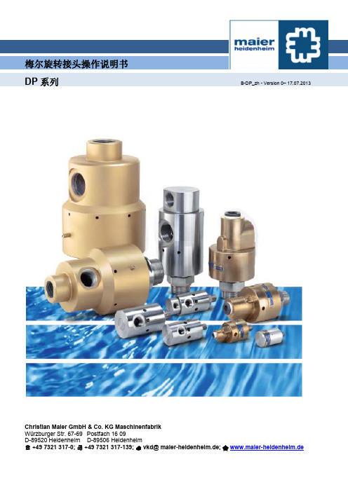
梅尔旋转接头操作说明书DP系列B-DP_zh - Version 0– 17.07.2013Christian Maier GmbH & Co. KG MaschinenfabrikWürzburger Str. 67-69 Postfach 16 09D-89520 Heidenheim D-89506 Heidenheim+49 7321 317-0; +49 7321 317-139; ***********************; www.maier-heidenheim.de梅尔旋转接头操作说明书DP系列B-DP_zh -Version 0 – 17.07.2013目录1 安全 (2)2 设计和功能 (3)3 设计和安装信息 (4)4 运输和储存 (4)5 安装 (5)6 操作 (7)7 维护 (8)本手册版权归Christian Maier GmbH & Co. KG所有。
本手册中包含的说明、信息和插图不得以任何方式进行全部或部分复制。
本手册中的说明、信息和插图也不得透露给任何第三方,或者用于制造同类竞争性产品、系统或者设备,或以任何方式协助此类活动。
梅尔旋转接头操作说明书DP 系列B-DP_zh -Version 0 – 17.07.20131. 安全目的梅尔旋转接头是一种专门用于连接压力管道和旋转压力系统的装置。
例如旋转压力系统是通过旋转接头向辊筒内部输送水或蒸汽。
该DP 系列旋转接头主要用于水。
DP...-800系列适用于载热油。
若是其他液体,请与厂家联系。
关于适用介质及其质量和性能,详情请参见“应用参数和备件”。
旋转接头应用中,不得超过手册中“应用参数和备件”规定数值。
切勿修改旋转接头,因为这可能会造成危害。
请务必按照操作手册中的说明来安装、操作和维护旋转接头。
对于一切未遵守操作说明而造成的损坏,我司概不负责。
这些操作说明中并不包含全部有关旋转接头安全操作的重要信息。
气管普通快速接头操作方法

气管普通快速接头操作方法气管普通快速接头是一种常见的气动接头,通过它可以快速、方便地连接或断开气体管道。
使用气管普通快速接头需要遵循一定的操作方法,下面将详细介绍。
首先,使用气动工具之前,务必检查工具是否正常运行,并确保工具的气源压力符合使用要求。
接下来,确认气管的管材和规格是否与快速接头相匹配。
在选用快速接头时,应注意其连接方式、内径、外径等参数,确保与气管相符。
在连接快速接头之前,需要保持接头和气管的端口清洁。
可使用气动清洁剂或清洗布进行擦拭,确保无灰尘、油污等杂质。
接头连接操作分为以下几个步骤:1. 从气管的一端移除接头保护盖。
2. 插入快速接头:将接头的插孔对准气管的连接口,稍加旋转使其对齐,然后轻推插入,直至插头的安全锁卡槽和气管的安全锁卡槽完全卡住。
3. 测试连接:确认插头已完全插入气管,可以轻轻牵拉接头,确保连接牢固。
如果连接不牢固,应重新插入。
4. 拆卸快速接头:先将接头的插销轻压一下,然后同时推动气管和接头,使其分离。
注意在分离过程中应保持气源关闭,避免气体喷射。
需要注意的是,在操作中要避免过度旋转接头,以免损坏接头的密封结构。
同时,应定期清洁和保养接头,避免灰尘、油污等污染导致接头失效。
此外,还需要根据实际使用需求选择合适的接头材质。
常见的材质有铜合金、不锈钢等,需根据工作环境、工作压力等因素进行选择。
总之,正确操作气管普通快速接头需要注意清洁、对齐、插入、测试和拆卸等步骤,确保安全、牢固的连接。
另外,还需定期检查接头的密封性能,保持接头的良好工作状态。
通过正确操作和维护,可以延长接头的使用寿命,提高工作效率。
旋转接头使用说明
本文由滕州市天旋旋转接头制造有限公司提供
旋转接头使用说明
下面为大家讲解一下旋转接头的正确使用方法
1、机器长期不使用会导致旋转接头的生锈损坏,再使用时会有卡死或泄漏情形发生。
2、不要让回转中心不正的旋转接头继续运转,应及时更换,以免发生意外情形造成伤害。
3、旋转接头的出入口一定要装软管,绝对不能用钢管代替。
软管也要选择挠性好的并保持适当的长度。
4、旋转接头的出入口不要外加其他配备(如阀门,过滤器),要加也要加在软管之后的管路上面。
5、旋转接头的固定支撑装置要适当,不能限制摆动和后退追随功能。
6、旋转接头的旋转轴和内管有左旋和右旋之分,安装和设计时应注意正确的旋向。
7、使用符合条件的旋转接头(参考介质、尺寸、压力、温度、转速、旋向、内管等事项)。
8、内管要选择适当的长度,并考虑接头承受的重量。
9、使用螺纹式旋转接头要注意螺纹规格是否正确及锁入滚轮的长度是否足够。
10、在未通介质时,应避免长时间运转。
气动旋转接头
气动旋转接头
一、气动旋转接头工作原理:
气动旋转接头内部采用进口高速轴承支撑,支撑着旋转接头的转子的前段与后端,使得旋转接头的整体平衡发展,同时减少旋转接头转子重量,可以减少内部的摩擦力,从而减少旋转阻力,保证了旋转速度,气动旋转接头经常配合高速旋转平台使用,旋转接头速度分段,0-100r/s属于低速型,100-600r/s属于中速型,600r/s以上属于高速型,针对不同的速度的旋转接头,旋转内部结构不一样,密封件也不一样,根据设计选择最适合旋转接头使用的密封件,达到最好效果,
二、气动旋转接头的分类:气动旋转接头按尺寸分国标气动旋转接头和非标气动旋转接头按通道分单通气动旋转接头、双通气动旋转接头、多通道气动旋转接头流体介质分为水、蒸汽、热油、空气与真空、液压油、冷却水。
三、气动旋转接头特点:体积小,重量轻,磨擦扭距小等优点
四、气动旋转接头用途:用于冶金机械、电气自动化、电子配套服务、冶金化工等领域本文有滕州新天机械有限公司整理发布
第 1 页共 1 页。
SL450A旋转接头操作手册说明书

SL450A ROTARY SWIVEL OPERATION MANUALSL450A-SMGoldenman Petroleum Equipment Co., Ltd Add:7/F, Wanda International Mansion, 67 Fuqian Street , Dongying China Tel:+0086-546-8058779 E-mail:********************CONTENTSI.Technical specifications (2)II.Structure instructions (2)III.Installation (3)IV.Operation (4)V.Lubrication (4)VI. Replacement of Packing Device (4)VII.Maintenance (5)VIII.Inspection and Debuggingent (6)IX.Packing and Shipping (7)X.Recommended Spares List (8)Please read the following operation manual before installing and operating the Swivel. It is necessary to confirm its maximum static loading for operation.The design and operation temperature for the product is -20°C(-4°F). It is necessary to inform lowest working temp when order the product.Regularly conduct NDT on main bearing parts (housing, central pipe, bail and bail pin).I. Technical Specification1. Max. Static Load 4500kN2. Max. RPM 300r/min3. Max. Working Pressure 35MPa4. Central Pipe ID. Ø75mm5. Sub connection 65/8 REG L.H.6. Gooseneck connection 4 LP API Std5B7. Air motor model FMS208. Air pressure 0.7-0.9MPa9. Air consumption 20m3/min10. Spinning speed 92rpm11. Brake torque 2940N.m12. Weight 3310kgII. Structure InstructionsSee Fig.1, SL450A rotary swivel consists of rotary part, fixed part, support part, sealing part and spinning part. Rotary part is composed of central pipe(14) and sub(24). Fixed part includes housing(15), upper cover(2), lower cover(18), gooseneck(10), bail(25) and bail pin (7). Support part consists of main bearing (16), guide bearing (12), and lower guide bearing (20). Seal part includes packing device and upper and lower seal rings. Spinning part covers air motor, air control clutch.Central pipe supports whole weight of drill string and inner mud pressure. Its connection thread with sub and the connection thread of sub and kelly meet API Spec 7-1 and 7-2 requirements.Central pipe is a kind of hollow part. Its upper end connects with packing device (Fig.1),its lower end connects with sub, and its middle part sits on the main bearing with two guide bearings centralize it, among which the upper guide bearing also has the function to avoid central pipe going up. Rubber umbrella (4) on top of the central pipe prevents mud from entering into swivel body.Bail which connects housing via two bail pins is to hang the swivel on the hook. Housing is a support part and is a oil pool for lubricating and cooling main bearings and guide bearings. On its two ends are top cover and bottom cover, on the external size is fitted with buffer (9) to avoid elevator ring impacting housing. Under the top cover is equipped with guide bearing and two oil seals(8). Those two seal rings should be installed in opposite directions, which will prevent oil leaking and mud entering. In top cover there is a thread hole fitted with an oil scale with relief valve function. When air pressure inside housing is higher than outside, the valve will auto open and discharge air. The gooseneck with a thread hole in the top is fixed on the top cover flange. The thread hole is designed for well logging. In drilling process, the hole is sealed with a plug (1) to avoid mud spilling. One end of gooseneck is connected with packing device, the other end is to connect with rotary hose via inner joint (API Std. 5B). Inside the lower cove is fitted with lower guide bearing with three oil seals (21).The packing device connects with the central pipe and the gooseneck pipe, which forms passage for drilling fluid. The packing device is an important part for sealing high pressure mud. It features self-sealing and quick disassembling structure. When wash pipe and packings are worn and needed to be replaced, only need to screw off the upper and lower nuts, then you can take out the whole device from one side, no need to disassemble gooseneck or rotary swivel. Simple, convenient, and can replace any time.Power reducer assembly (11) is secured with bolts and nuts on the upper plane of lower flange of top cover (2). It is an important part for spinning. Spinning is realized by control air valve. Look down at central pipe, clockwise rotation is called forward rotation and anti-clockwise rotation is reverse rotation.III. InstallationRefer to Fig.2 for installation of the spinner. Main control valve (8, left) controls the swivel’s spinning working and its stop. Reverse control valve is to invert the swivel’s rotation. Care should be taken to shut off the main air-in valve (20) when need to change rotation direction of the spinner.IV. OperationLoad test and dynamic pressure test for a new swivel have been conducted before leaving the manufacturing plant, and there is no oil in the swivel housing. So before use, must do the following.1. Unscrew and remove the oil scale, fill with lubricate L-CKC150 (to max. scale), and be sure the oil is clean.2. Inspect the central pipe. Rotate the pipe by a person with a one-meter long Chain tongs. The central pipe should turn evenly.3. Lubricate all grease fittings with gun.4. Check glands of upper and lower packing box (Fig.3, No.1 and No.10), gooseneck union nut (Fig.1,No.10) and sub (Fig.1, No.24) for tight. To ensure good connection and no damage on thread, it is necessary to screw off the sub and apply with thread grease, and tighten with rotary tong.5. Check all air line connections for correct and ensure unobstructed air flow.6. Air filter (Fig.2-19) should be fitted vertically.7. Never allow air motor to run idly.8. According to fields operation experience, new swivel should be used for shallow well, then to deep well, which is good for service life of the swivel.V. Lubrication1. Inspect oil level in the housing of the swivel every shift to see if oil level is higher than minimum limit(never allow oil being le. Replace lubrication oil every 2 months or every 200 hours for new and repaired swivels. Before injecting clean L-CKC150(winter), L-CKC220(summer), flush away dirty oil.2. Lubricate bail pins, packing device and oil seals inside supporting frame with lithium based grease No.1 (winter),or No.2 (summer). Once every shift. Packing must be lubricated when no pump pressure, so the grease can squeeze into every corner of packing and lubricate wash pipe and packing perfectly.3. Check oil level height inside lubricator. The lubricator should be injected with L-AN15 machine oil.VI. Replacement of Packing Device1. Disassemble (Refer to Fig.3)Hammer the nut (LH)(1) until it loose and flush wash pipe(6), then push out packing device from one side of the supporting frame.Separate lower packing box (12) from wash pipe, remove grease fitting (7), take out lower lantern ring (15), spacer rings (13,14), packings (4) and O-rings (9) from lower packing box.Remove stop ring from top side of wash pipe. And take out wash pipe, lantern ring (3), packing and O-ring.2.Inspection2.1 Clean all parts thoroughly.2.2 Check wear and tear. Replace worn and damaged parts.3.InstallationReassemble qualified and replaced parts.3.1Install packings and upper lantern ring coated with grease into upper packing box, and screw on nuts.3.2Put splined end of wash pipe through and install retainer ring.3.3Screw the nut on lower packing box. Put grease-coated packings, spacer ring, and lower lantern ring into lower packing box in proper order.3.4Put non-splined end of wash pipe through into packing carefully.3.5Put in the O ring and grease fitting.3.6Insert packing device into swivel and tighten upper and lower nuts.VII. Maintenance1. Disassemble as per the following steps. Refer to Fig.1.1.1 It is recommended to unscrew the saver sub on end of stem prior to demounting the swivel from rig.1.2 Hold straight the swivel while dismantling.1.3 Screw out plug (27) and plug (28) and drain oil.1.4 Dismount the reducer assembly (11).1.5 Refer to Section V Replacement of Packing Device for demounting the packing device.1.6 Remove rubber umbrella (4) from top end of central pipe.1.7 Dismantle gooseneck (10) and upper cover(2).1.8 Remove adjustment shims.1.9 Dismantle central pipe assembly (including central pipe, upper seat ring of mainbearing, inner rings of upper and lower guide bearings, and upper and lower bushings.)1.10 Take out main bearing carrier, lower seat ring and rollers from housing.1.10 Remove gland (18), tap the outer ring of lower guide bearing (20) and take it out from lower cover, then remove gland on the lower cover. So it is available to take out two oil seal rings and space ring from lower cover. Then remove grease fitting and O seal ring.2. Check and replace parts.2.1It is recommended to replace with new oil seals and O-rings when inspecting the swivel or replacing parts.2.2Check all bearing rollers and seats for broken, worn, corrosion and crack, especially for main bearing, if any defect occurs replace right away, to ensure reliable working performance. Upper seat and lower seat of the main bearing can not be interchanged, as upper seat is transition fitted with central pipe. For dismantling, only need to knock its seat off central pipe. If necessary, heat it to 65-100℃is favorable.3. Reassemble3.1Apply enough grease on lips of two oil seals and then fit into upper cover. Remember the installation of two oil seals should be on the contrary, and separated by spacer ring for lubrication. Secure with stop ring and tap guide bearing (12) into upper cover.3.2Tap out-ring of lower guide bearing (20) into lower cover and fit lower cover into housing.3.3 Set assembled housing upright on the supporter and put the lower ring of main bearing, rollers and holder into the housing.3.4 Put central pipe assembly into the housing.3.5 Turn central pipe assembly slightly to ensure the firm of main bearing.3.6 Install the assembled upper cover to the housing.3.7 Turn the central pipe assembly again to see if all the bearings is set firmly.3.8 Check the clearance between the bottom face of upper cover flange and upper face of housing. Remove the lower cover and put enough adjusting shims (16) to ensure the axial clearance within range 0.05mm~0.25mm.3.9 Enclose the upper cover to the housing. And tighten the screw bolt.3.10 Install rubber umbrella, gooseneck, packing device and joint (sub).3.11 Fix the grease fittings and screw in plugs. Then fill with oil and that will be ok for use.VIII. Inspection and DebuggingInspection and debugging is important in the course of assembly, which will affectservice life of parts. It is recommended to inspect and debug the swivel as per the following procedure.1. The clearance between end faces of upper seat ring of main bearing and central pipe must not be more than 0.03mm.2. Adjusting shims between upper cover and housing are for adjusting the axial clearance of upper guide bearing (12); the clearance should be within range 0.05~0.25mm.3. Inspect the following radial run-out with micrometer.3.1 Inspect upper cover hole as per Fig.4. Radial run out should not be over 0.20mm.3.2 Inspect gooseneck as per Fig. 5. Radial run out should not be over 0.30mm.3.3 Inspect mud pipe as per Fig. 6. Radial run out should not be over 0.30mm.If the radial run-out measured is more than the above range, you should adjust radial run-out of upper cover and gooseneck by releasing upper and lower packing box glands, tapping wash pipe and changing the tightening degree of bolts. Ensure radial run-out is within the specified range, and packing device working under best condition.3.4 Reducer assembly (Fig.7)3.4.1 When to install round nut, adjust bearing to its suitable tightness (Gear can turn freely by hand), then secure.3.4.2 Check clearance between internal and external friction pieces (18,25), keep it in the range of 0.5mm~0.8mm, adjust with shims.3.5 Contact point of gear ring of central pipe (Fig.1, 13) with gear shaft (Fig.7, 15) along depth of tooth should not be less than 40%, along length of tooth not less than 60%.3.6 Connect well air motor, transmission system and air control system.3.6.1 Check air line connection if correct.3.6.2 Check air control console if smooth. Rotation in forward and reverse meets requirements.3.6.3 One-way friction clutch engages normally.IX. Packing and Shipping1. Fix the swivel evenly on the supporter. Air directional valve and vent hole in the air motor should be wrapped with plastic cloth or insert with wood plug. Sub under central pipe should be fitted with a screw protector. Inner joint in the gooseneck should be fitted with protective cap.2. Use a lifting device when move and install the swivel, do not tow it directing on the ground.3. When the swivel is idle for a long time, keep it in a dry and ventilated place. Prior to storage, clean up oil and sediment inside the housing of the swivel, and apply anti-rust oil on threads, bearings, and exposed surface.X. Recommended Spare Parts ListNo. Part No.Description Qty.1RS78.120.00Packing device 12RS78.120-04Packing 103RS78.120-07Snap ring 14RS78.120-06Wash pipe 15RS78.100-09Bail pin 26RS78.100-07Upper bushing 17RS78.100-18Lowe bushing 18JB/ZQ4224O-ring 120*5.759JB/ZQ4224O-ring 135*5.7310JB/ZQ4224O-ring 560*8.6111JB/ZQ4224O-ring 560*3.1112HG-692-67Oil seal SD220*260*18213HG-692-67Oil seal SD250*290*18314RS78.100-06Rubber umbrella 115RS78.310-24Pinion 116Bearing 94754 Q4117RS78.310-22External friction pieceⅠ118RS78.310-21External friction piece Ⅱ119RS78.310-20External friction piece Ⅲ120RS78.310-18External friction piece Ⅳ121RS78.310-17External friction piece Ⅴ122RS78.310-23Internal friction piece Ⅰ223RS78.310-19Internal friction piece Ⅱ224RS78.310-16Internal friction piece Ⅲ2Parts list for Figure 1:No.Part No.Description Qty.No.Part No.Description Qty.1RS76.100-02Plug NPT2116Bearing 94754 Q41 2RS78.300-04Upper cover 117JB/ZQ4224O-ring 560*8.61 3RS78.120.00Packing device 118RS78.100-13Lower cover1 4RS78.100-06Rubber umbrella 119RS78.100-23Lantern ring 1 5HG4-692-67Oil seal D220*260*18220GB/T283Bearing NU104816RS78.100-07Upper bushing121HG4-692-67Oil sealSD250*290*1837RS78.100-09Bail pin222RS78.100-18Lower bushing 18JB/T7940.1Grease fittingM10*1323RS78.100-15Gland19RS78.110.00Cushion 124RS76.100-16Sub 1 10RS78.100-02Gooseneck 125RS78.100-01Bail 1 11RS78.310.00Reducer assy.126RS78.320.00Oil scale 1 12GB/T297Bearing 32040X2127JB/ZQ4446Plug R11 13RS78.300-02Gear ring128JB/ZQ4450Plug M12*1.251 14RS78.300-05Central pipe129JB982Washer 121 15RS78.300-03Housing 1Parts list for Figure 2:No.Part No.Description Qty.No.Part No.Description Qty. 105-03Goose neck 1No.Part No.Description Qty.2XSL160.2C-19Transition jointM39*2-Rc11/2113GB/T3287Reducing jointG11/2-G11305-05Transition jointM52*2-Rc11/2114GB/T3287Inner joint R11405.03.00Hose with joint25*20000115GB/T3287Union jointG11/225Hose 38I*20m 116GB/T3287Inner joint R11/2 4 6A01.5200.000Hose 10*20m 21714.09.01-04A Angle joint 3 705-07Transition joint M18*1.511805-04Four-way joint1 8QF501A Air valve Rc1/4219QSL-40Filter G11/21 9A01.5200.000Hose 10*6m 320Q11F-16Ball valve G11/2 1 10A01.5000-004Joint 321QIU-40Lubricator G11/2 11105-06Transition jointM52*2-R11Fig.1 Outline of SwivelFig.2 Installation of SL450A Swivel (recommended)No.Part No.Description Qty. remarks1RS78.120-01Upper packing box gland 12RS78.120-07Snap ring 13RS78.120-03Upper seal gland 14RS78.120-04Packing55RS78.120-02Upper packing box 16RS78.120-06Wash pipe17JB/T7940.1Grease fitting M10*118GB/T75Screw M10*1219JB/ZQ4224O seal ring 120*5.7110RS78.120-13Lower packing box gland 111RS78.120-12Lowe seal gland 112RS78.120-10Lower packing box 113RS78.120-11Spacer ring Ⅱ214RS78.120-09Spacer ring Ⅰ115RS78.120-08Lower bush ring 116RS78.120-05Upper bush ring 117JB/ZQ4224O seal ring 135*5.71Fig.4 Inspection and Adjustment for AssemblyFig.5 Inspection and Adjustment for AssemblyFig.6 Inspection and Adjustment for AssemblyParts list for Figure 7:No.Part No.Description Qty.No.Part No.Description Qty. 1FMS20Air motor116RS78.310-15Spring10 2Bearing NU207117GB/T276Bearing 60091 3RS78.310-01Gear118RS78.310-16Friction piece III24GB/T292Bearing 7010C119RS78.310-17External frictionpiece Ⅴ15RS78.310-03Spacer plate120RS78.310-18External frictionpieceⅣ16GB/T301Bearing 51120121RS78.310-19Internal frictionpiece Ⅱ27RS78.310-04Gasket122RS78.310-20External frictionpiece Ⅲ18RS78.310-25Shims1组23RS78.310-21External frictionpiece Ⅱ19GB/T119.1Pin 12n6*32224RS78.310-23External frictionpieceⅠ110GB/T301Bearing 51118125RS78.310-22Internal frictionpieceⅠ111JB/ZQ4224O-ring 175*8.6126JB/ZQ4224O-ring 16*2.41 12JB/ZQ4224O-ring 110*5.7127RS78.310-24Pinion1 13JB/ZQ4224O-ring 180*3.1128A01.5200.00Hose 10*500114GB/T283BearingNU2210M129K24JQ.L40.00Directional valve115RS78.310-12Gear shaft13005.01.50.00I Hose jointFig.7 Power Reducer Assembly。
简述SMC气动旋转接头
简述SMC气动旋转接头SMC旋转接头可依工作情形来选择连结方式。
传输介质入口可依工作情况自由选择侧边或后端进入。
密封面及密封圈为特殊材料所制成的,抗磨损、寿命长、耐腐蚀、不泄漏。
旋转接头内部有两个精密轴承,运转平稳持久、坚固灵活,磨擦系数小,故可以高速运转。
内部密封件磨损的状况可由产品外观目测得知,可以预防机械停机或机械损坏,来达到预防的效果和减少损失。
密封件磨损更换维修简易,不用重新购置新品,节省成本。
单回路系列旋转接头:满足国内外各种产业需求,流体介质水(water)、蒸气(steam)、油(oil)、空气(Air)、真空(vacuum)切削液(coolant)、甲苯等化学溶剂。
1、、SMC气动旋转接头连接形式:SMC旋转接头可分为双回路固定式和双回路旋转式旋转接头。
密封面及密封圈为特殊材料所制成的,抗磨损、寿命长、耐腐蚀、不泄漏。
内部密封件磨损的状况可由产品外观目测得知,可以预防机械停机或机械损坏,来到预防的效果和减少损失。
内有独立管路,可作不同工作情况需求做选择,来发挥最大的效益。
外壳与转轴由精密轴承支撑,使旋转转动时灵活轻巧,磨擦力小,液体介质可包括水、油、空气等,运用行业甚广。
密封件磨损更换维修简易,不用重新购置新品,节省成本。
2、、smc气动旋转接头安装注意事项:1、MC旋转接头在搬运和存放过程中应避免撞击和摔落,以免损坏接口及内部零件。
2、尽可能装机同心,以确保旋转接头的良好运转。
3、螺纹连接的旋转接头在安装时,应注意内、外管的螺纹向是否滚筒的旋转方向对应,且内外管的螺纹旋向也应一致。
4、SMC旋转接头与管道之间的连接,必须使用软管相连接(我们公司推荐使用扰性好的金属软管),绝对禁止刚性连接。
5、SMC旋转接头的出入口尽可能直接与软管相连接。
以减轻接头辅重,延长使用寿命。
6、内管的装配,注意尺寸的配合及重量的辅助支撑。
内旋式旋转接头的内管与接头的配合推荐使用H8/e7的公差配合。
气动旋转接头使用说明
气动旋转接头系专门为适用于气动控制方面设计的系列产品。
气动旋转接头组件包括接头、过滤器、电磁阀、气缸、真空设备、气管等。
气动旋转接头可分为多通路气动旋转接头,单通路气动旋转接头,高速气动旋转接头,高压气动旋转接头,非标气动旋转接头等
气动旋转接头的使用事项:
1、禁止说明书所示产品的参数,条件以外的使用范围;
2、禁止在过大的振动,冲击旋转及弯曲的场所使用气动旋转接头;
3、禁止拆卸或改制产品,存在误动作或泄漏的可能;
4、气动旋转接头维修及定期检查时,请在完全排除配套系统内的流体后再进行;
5、在管接头内有压力的情况下,不要触碰管套
6、不要使气动旋转接头上受外部负荷(弯曲、扭曲、牵拉),不然有可能损坏或泄漏;
7、如把水作为流体使用时,其使用压力不应超过0-3kgf/cm2
本文有滕州新天机械有限公司整理发布。
- 1、下载文档前请自行甄别文档内容的完整性,平台不提供额外的编辑、内容补充、找答案等附加服务。
- 2、"仅部分预览"的文档,不可在线预览部分如存在完整性等问题,可反馈申请退款(可完整预览的文档不适用该条件!)。
- 3、如文档侵犯您的权益,请联系客服反馈,我们会尽快为您处理(人工客服工作时间:9:00-18:30)。
气动旋转接头系专门为适用于气动控制方面设计的系列产品。
气动旋转接头组件包括接头、过滤器、电磁阀、气缸、真空设备、气管等。
气动旋转接头可分为多通路气动旋转接头,单通路气动旋转接头,高速气动旋转接头,高压气动旋转接头,非标气动旋转接头等
气动旋转接头的使用事项:
1、禁止说明书所示产品的参数,条件以外的使用范围;
2、禁止在过大的振动,冲击旋转及弯曲的场所使用气动旋转接头;
3、禁止拆卸或改制产品,存在误动作或泄漏的可能;
4、气动旋转接头维修及定期检查时,请在完全排除配套系统内的流体后再进行;
5、在管接头内有压力的情况下,不要触碰管套
6、不要使气动旋转接头上受外部负荷(弯曲、扭曲、牵拉),不然有可能损坏或泄漏;
7、如把水作为流体使用时,其使用压力不应超过0-3kgf/cm2
本文有滕州新天机械有限公司整理发布。