18-45KW普乐特控制器说明书
普乐特控制器设置说明
关于我公司变频控制器升级说明:
为了方便客户使用我公司变频控制器,适应不同品牌变频器通信,读取变频器运行参数的需求,我公司新升级了变频控制器软件版本,介绍如下:
1、 此版本软件能适应所有支持MODBUS RTU 协议的变频器。
(变频器需要能直接读取输出电流、输出电压、输出频率、输出功率)
2、 控制器内部已集成了38种型号的变频器通信协议,当用户所需的变频器不在这些型号范围内时,可自行设置通信参数。
设置步骤如下:
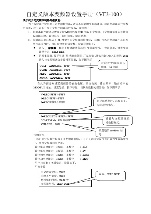
● 进入 厂家参数 移动下移键滚动条选到 变频器型号: 设置菜单,设置变频器型号为:SELF-DEF 。
● 返回主界面,按下移键,移动滚动条到 厂家参数 ,按右移键,输入的密码 2688
在此界面分别设置变频器的输出电压、输出电流、输出频率、输出功率的MODBUS 地址,设置好后,按下移键,切换到数据处理界面:如下图所示
客户需要与森兰SB70变频器通信,
SB70通信协议没有内置到变频器型号中,经查变频器通信手册。
输出电流地址为:1202H ,小数位 0.01A
输出电压地址为:1204H ,小数位 0.1V
输出频率地址为:1200H ,小数位 0.01HZ
输出功率地址为:1208H ,小数位 0.1KW
用户与SB70通信进,设置如下:
厂家参数:
返回主界面,按下移键,移动滚动条到厂家参数,按右移键,输入的密码2688,。
普乐特空压机控制器MAMVF
压力上限
**.**MPa
开机后,当压力大于此处设置值时,控制器控制空压机卸载运行.
风机启温度
0080℃
转速(50Hz)
****RPM
设置电机50HZ时对应转速,用于电机变频工作时,计算电机的实际转速。
启停延时预置
风机启动时间
0006秒
控制器保护电机时要求此时间能躲过电机启动冲击电流
加载延时时间
0002秒
空压机启动后,延时此处设置时间后,加载运行。
空载延时时间
0020分
空压机允许的最长连续空载运行时间,超过此时间后自动停车。
在如上所示界面中,按移位键,压力下限的第一个数据位开始闪烁,用户可以按递增键或递减键,修改当前的闪烁位数据等于目标值后,按移位键,移动闪烁光标到下一个数据位,继续按上述方法修改数据等于目标值,修改完所有数据位后,按确认键,保存用户设定数据.
4、用户参数表及功能
一级菜单
二级菜单
设定初值
功能作用
压力、变频参数
润滑油累计使用时间,更换润滑油后,在此处清零。
润滑脂
0000小时
润滑脂累计使用时间,更换润滑脂后,在此处清零。
最大使用时间预置
油滤器
****小时
油滤器累计使用时间超过此处设置值后,预警提示;设为“0000”时,油滤器使用时间预警不起作用
油分器
****小时
油分器累计使用时间超过此处设置值后,预警提示;设为“0000”时,油分器使用时间预警不起作用。
操作方式预置
18-45KW普乐特控制器说明书
电脑控制器使用说明电脑控制器主要功能有监视压缩机运行状态,控制压缩机,保护压缩机,监控保养零件等。
电脑控制器是空压机的控制核心,对机组正常运行起关键作用,故请用户使用前详细阅读本控制器使用说明。
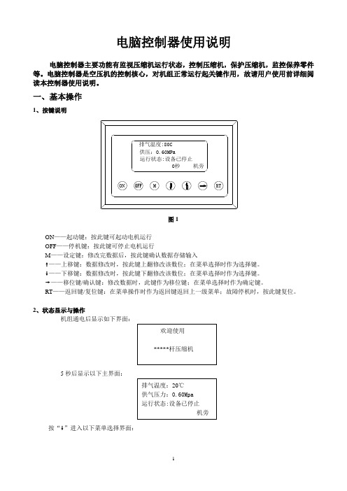
一、基本操作1、按键说明图1ON——起动键:按此键可起动电机运行OFF——停机键:按此键可停止电机运行M——设定键:修改完数据后,按此键确认数据存储输入❽——上移键:数据修改时,按此键上翻修改该数位;在菜单选择时作为选择键。
❾——下移键:数据修改时,按此键下翻修改该数位;在菜单选择时作为选择键。
❼——移位键/确认键:修改数据时,此键作为移位键;在菜单选择时作为确定键。
RT——返回键/复位键:在菜单操作时作为返回键返回上一级菜单;故障停机时,按此键复位。
2、状态显示与操作机组通电后显示如下界面:5秒后显示以下主界面:按“❾”进入以下菜单选择界面:a、运行参数查看按“❾”或“❽”移动黑色滚动条到“运行参数”菜单后,按确认键“❼”后弹出下一级菜单:再按“❼”弹出如为最后一级菜单,界面不会出现黑色滚动条,按返回键“RT”返回上级菜单或主界面。
如在某一界面停止操作,数秒钟后自动返回主界面。
用“❾”、“❽”移动键、确认键“❼”和返回键“RT”根据上述方法可完全观察到运行时间、本次运行时间、维护参数、历史故障、出厂日期、现场故障等运行参数并返回到上级菜单。
b、日历时间按“❾”或“❽”移动黑色滚动条到“日历”菜单后,按确认键“❼”后弹出在停机状态下可对日期、时间进行调整,操作方法为:按“❾”或“❽”移动黑色滚动条到需修改的参数项后按确定键“❼”后出现闪烁位,此时“❾”和“❽”键变为上翻和下翻键修改当前位,“❼”变为移位键移动修改位。
修改完毕后按“M”确认并保存,“❾”或“❽”变回移动黑色滚动条,“❼”变回返回键。
c、用户参数1)、参数修改方法══在运行状态和停机延时过程中不能修改用户参数和厂家参数══用前述运行参数查看的方法可查看和修改用户参数,如修改压力上限,操作方法如下:按“❾”或“❽”移动黑色滚动条到“用户参数”项后按确定键“❼”弹出再按确定键 “❼”弹出如不继续按确定键 “❼”即可查看用户参数。
Pololu 简单高功率电机控制器 V2.3说明书
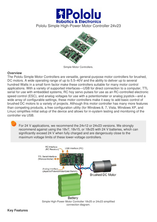
Pololu Simple High-Power Motor Controller 24v23Simple Motor Controllers.OverviewThe Pololu Simple Motor Controllers are versatile, general-purpose motor controllers for brushed, DC motors. A wide operating range of up to 5.5–40V and the ability to deliver up to several hundred Watts in a small form factor make these controllers suitable for many motor control applications. With a variety of supported interfaces—U SB for direct connection to a computer, TTL serial for use with embedded systems, RC hoy servo pulses for use as an RC-controlled electronic speed control (ESC), and analog voltages for use with a potentiometer or analog joystick—a nd a wide array of configurable settings, these motor controllers make it easy to add basic control of brushed DC motors to a variety of projects. Although this motor controller has many more features than competing products, a free configuration utility (for Windows 8, 7, Vista, Windows XP, and Linux) simplifies initial setup of the device and allows for in-system testing and monitoring of the controller via USB.For 24 V applications, we recommend the 24v12 or 24v23 versions. We stronglyrecommend against using the 18v7, 18v15, or 18v25 with 24 V batteries, which cansignificantly exceed 24 V when fully charged and are dangerously close to themaximum voltage limits of these lower-voltage controllers.Simple High-Power Motor Controller 18v25 or 24v23 simplifiedconnection diagram.Key FeaturesSimple bidirectional control of one DC brush motor.5.5 V to 30 V (18v7, 18v15, and 18v25) or 40 V (24v12 and 24v23) operating supply range.7 A to 25 A maximum continuous current output without a heat sink, depending on controller modelFour communication or control options:1. USB interface for direct connection to a PC.2. Logic-level (TTL) serial interface for direct connection to microcontrollers orother embedded controllers.3. Hoy radio control (RC) pulse width interface for direct connection to an RCreceiver or RC servo controller.4. 0–3.3 V analog voltage interface for direct connection to potentiometers andanalog joysticks.Simple configuration and calibration over USB with free configuration program (Windows 8, 7, Vista, Windows XP, and Linux compatible).Note: A USB A to mini-B cable (not included) is required to connect this controller to acomputer.Additional FeaturesComprehensive user’s guide with plenty of connection diagrams and sample code.Adjustable maximum acceleration and deceleration to limit electrical and mechanical stress on the system.Adjustable starting speed, maximum speed, and amount of braking when speed is zero.Optional safety controls to avoid unexpectedly powering the motor.Input calibration (learning) and adjustable scaling degree for analog and RC signals.Under-voltage shutoff with hysteresis for use with batteries vulnerable to over-discharging (e.g. LiPo cells).Adjustable over-temperature threshold and response.Adjustable PWM frequency from 1 kHz to 22 kHz (maximum frequency is ultrasonic, eliminating switching-induced audible motor shaft vibration).Error LED linked to a digital ERR output, and connecting the error outputs of multiple controllers together optionally causes all connected controllers to shut down when any one of them experiences an error.Field-upgradeable firmware.USB/Serial features:Controllable from a computer with native USB, via serial commands sent to the device’s virtual serial (COM) port, or via TTL serial through the device’s RX/TX pins.Example code in C#, Visual Basic .NET, and Visual C++ is available in the Pololu USB Software Development KitOptional CRC error detection to eliminate communication errors caused by noise or software faults.Optional command timeout (shut off motors if communication ceases).Supports automatic baud rate detection from 1200 bps to 500 kbps, or can be configured to run at a fixed baud rate.Supports standard compact and Pololu protocols as well as the Scott Edwards Mini SSC protocol and an ASCII protocol for simple serial control from a terminal program.Optional serial response delay for communicating with half-duplex controllers such as the Basic Stamp.Controllers can be easily chained together and to other Pololu serial motor and servo controllers to control hundreds of motors using a single serial line.Two Pololu Simple Motor Controllersenable mixed RC-control of Dagu WildThumper 4WD all-terrain chassis.RC features:1/4 µs pulse measurement resolution.Works with RC pulse frequencies from 10 to 333 Hz.Configurable parameters for determining what constitutes an acceptable RC signal.Two RC channels allow for single-stick (mixed) motor control, making it easy to use two simple motor controllers in tandem on an RC-controlled differential-drive robot (you might find our RC servo Y splitter cables useful for connecting two SMCs to a single RC receiver).RC channels can be used in any mode as limit or kill switches (e.g. use an RC receiver to trigger a kill switch on your autonomous robot).Battery elimination circuit (BEC) jumper can power the RC receiver with 5 V or3.3 V.Analog features:0.8 mV (12-bit) measurement resolution.Works with 0 to 3.3 V inputs.Optional potentiometer/joystick disconnect detection.Two analog channels allow for single-stick (mixed) motor control, making it easy to use two simple motor controllers in tandem on a joystick-controlled differential-drive robot.Analog channels can be used in any mode as limit or kill switches.This video demonstrates the versatility of the Simple Motor Controller by showing how it can be controlled directly from the analog output of a Sharp analog distance sensor—there is no intermediate control board and no programming involved. For more information on this example, including the SMC settings file and a list of parts used, see our blog post about the demo. Simple Motor Controller Comparison TableThe Simple Motor Controllers are available in several input voltage ranges and output current ranges:1significantly exceed 24 V when fully charged. The 24v12 and 24v23 are the much more appropriate controller for 24 V applications. 2 This is the weight of the board without header pins, terminal blocks, or through-hole power capacitor.Included HardwareSimple High-Power Motor Controller 18v15or 24v12, fully assembled.Simple High-Power Motor Controller 18v15or 24v12, partial kit with includedhardware.Most Simple Motor Controllers are available “fully assembled”, with the power capacitor and connectors pre-installed, or with these components included but not soldered in. For example, a fully assembled 18v15 ships as shown in the left picture above, and an 18v15 with included hardware ships as shown in the right picture above (the included hardware consists of a power capacitor, a 40×1 straight 0.1" male header strip, a 5mm-pitch 4-pin terminal block, and a blue shorting block).The connector-free version allows flexibility in choice of connectors and placement of the power capacitor (e.g. on the other side of the board) to accommodate compact installations or to make room for a heat sink.Note: The power capacitor has a significant effect on performance; the includedcapacitor is the minimum size recommended, and bigger ones can be added if there is space. A bigger capacitor might be required if the power supply is poor or far (more than about a foot) from the controller.The included terminal blocks are only rated for 16 A, so we recommend soldering thick wires directly to the connector-free version of the board and using higher-currentconnectors for applications that will exceed the terminal blocks’ ratings.Simple Motor Controller 18v7bottom view with dimensions.Simple High-Power Motor Controller 18v15 or 24v12bottom view with dimensions.Simple High-Power Motor Controller 18v25 or 24v23bottom view with dimensions.Warning: Take proper safety precautions when using high-power electronics. Make sure you know what you are doing when using high voltages or currents! During normal operation, this product can get hot enough to burn you. Take care when handling this product or other components connected to it.Documentation on producer website.。
Schneider Electric Altivar 61 HD 45 N 变速驱动器数据手册说明书
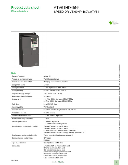
i s c la i me r : T h i s d o c u m e n t a t i o n i s n o t i n t e n d e d a s a s u b s t i t u t ef o r a n d i s n o t t o b e u s e d f o r d e t e r m i n i ng s u i t a b i l i t y o r r e l i a b i l i t y o f th e s e p r o d u c t s f o r s p e ci f i c u s e r a p p l i c a t i o n sProduct data sheetCharacteristicsATV61HD45N4SPEED DRIVE,60HP,460V,ATV61MainRange of productAltivar 61Product or component type Variable speed driveProduct specific application Pumping and ventilation machine Component name ATV61Motor power kW 45 kW 3 phases at 380...480 V Motor power hp60 hp 3 phases at 380...480 V [Us] rated supply voltage 380...480 V (- 15...10 %)Network number of phases 3 phasesLine current 104 A for 380 V 3 phases 45 kW / 60 hp 85 A for 480 V 3 phases 45 kW / 60 hp EMC filter Level 3 EMC filter Assembly style With heat sinkApparent power 68.5 kVA for 380 V 3 phases 45 kW / 60 hp Prospective line Isc 22 kA 3 phasesMaximum transient current 112.8 A for 60 s 3 phases Nominal switching frequency 12 kHzSwitching frequency1...16 kHz adjustable12...16 kHz with derating factorAsynchronous motor control profileVoltage/Frequency ratio, 2 points Voltage/Frequency ratio, 5 pointsFlux vector control without sensor, standardVoltage/Frequency ratio - Energy Saving, quadratic U/f Synchronous motor control profile Vector control without sensor, standard Communication port protocol CANopen ModbusType of polarization No impedance for ModbusOption cardAPOGEE FLN communication card BACnet communication card CC-Link communication cardController inside programmable card DeviceNet communication card Ethernet/IP communication card Fipio communication cardI/O extension cardInterbus-S communication cardLonWorks communication cardMETASYS N2 communication cardModbus Plus communication cardModbus TCP communication cardModbus/Uni-Telway communication cardMulti-pump cardProfibus DP communication cardProfibus DP V1 communication cardComplementaryProduct destination Asynchronous motorsSynchronous motorsSupply voltage limits323...528 VSupply frequency50...60 Hz (- 5...5 %)Network frequency47.5...63 HzContinuous output current77 A at 12 kHz, 460 V 3 phases94 A at 12 kHz, 380 V 3 phasesOutput frequency0.1...500 HzSpeed range 1...100 in open-loop mode, without speed feedbackSpeed accuracy+/- 10 % of nominal slip for 0.2 Tn to Tn torque variation without speed feedbackTorque accuracy+/- 15 % in open-loop mode, without speed feedbackTransient overtorque130 % of nominal motor torque, +/- 10 % for 60 sBraking torque30 % without braking resistor<= 125 % with braking resistorRegulation loop Frequency PI regulatorMotor slip compensation AdjustableAutomatic whatever the loadCan be suppressedNot available in voltage/frequency ratio (2 or 5 points)Local signalling 1 LED red presence of drive voltageOutput voltage<= power supply voltageIsolation Between power and control terminalsType of cable With an IP21 or an IP31 kit : 3-strand IEC cable at 40 °C, copper 70 °C PVCWithout mounting kit : 1-strand IEC cable at 45 °C, copper 70 °C PVCWithout mounting kit : 1-strand IEC cable at 45 °C, copper 90 °C XLPE/EPRWith UL Type 1 kit : 3-strand UL 508 cable at 40 °C, copper 75 °C PVCElectrical connection AI1-/AI1+, AI2, AO1, R1A, R1B, R1C, R2A, R2B, LI1...LI6, PWR terminal 2.5 mm² / AWG 14L1/R, L2/S, L3/T, U/T1, V/T2, W/T3, PC/-, PO, PA/+, PA, PB terminal 150 mm² / 300 kcmil Tightening torque L1/R, L2/S, L3/T, U/T1, V/T2, W/T3, PC/-, PO, PA/+, PA, PB 41 N.m / 360 lb.inAI1-/AI1+, AI2, AO1, R1A, R1B, R1C, R2A, R2B, LI1...LI6, PWR 0.6 N.mSupply Internal supply for reference potentiometer (1 to 10 kOhm) 10.5 V DC +/- 5 %, <= 10 mA for overloadand short-circuit protectionInternal supply 24 V DC (21...27 V), <= 200 mA for overload and short-circuit protectionExternal supply 24 V DC (19...30 V)Analogue input number2Analogue input type AI1-/Al1+ bipolar differential voltage +/- 10 V DC, input voltage 24 V max, resolution 11 bits + signAI2 software-configurable current 0...20 mA, impedance 242 Ohm, resolution 11 bitsAI2 software-configurable voltage 0...10 V DC, input voltage 24 V max, impedance 30000 Ohm,resolution 11 bitsSampling duration Discrete input LI6 (if configured as logic input) 2 ms, +/- 0.5 msAnalog input AI1-/Al1+ 2 ms, +/- 0.5 msAnalog input Al2 2 ms, +/- 0.5 msAnalog output AO1 2 ms, +/- 0.5 msDiscrete input LI1...LI5 2 ms, +/- 0.5 msAccuracy AI1-/Al1+ +/- 0.6 % for a temperature variation 60 °CAI2 +/- 0.6 % for a temperature variation 60 °CAO1 +/- 1 % for a temperature variation 60 °CLinearity error AI1-/Al1+ +/- 0.15 % of maximum valueAI2 +/- 0.15 % of maximum valueAO1 +/- 0.2 %Analogue output number1Analogue output type AO1 software-configurable current, analogue output range 0...20 mA, impedance 500 Ohm,resolution 10 bitsAO1 software-configurable logic output 10 V, <= 20 mAAO1 software-configurable voltage, analogue output range 0...10 V DC, impedance 470 Ohm,resolution 10 bitsDiscrete output number2Discrete output type(R1A, R1B, R1C) configurable relay logic NO/NC, electrical durability 100000 cycles(R2A, R2B) configurable relay logic NO, electrical durability 100000 cyclesResponse time<= 100 ms in STO (Safe Torque Off)R1A, R1B, R1C <= 7 ms, tolerance +/- 0.5 msR2A, R2B <= 7 ms, tolerance +/- 0.5 msMinimum switching current Configurable relay logic 3 mA at 24 V DCMaximum switching current R1, R2 on resistive load, 5 A at 30 V DC, cos phi = 1, 0 msR1, R2 on inductive load, 2 A at 30 V DC, cos phi = 0.4, 7 msR1, R2 on resistive load, 5 A at 250 V AC, cos phi = 1, 0 msR1, R2 on inductive load, 2 A at 250 V AC, cos phi = 0.4, 7 msDiscrete input number7Discrete input type(LI1...LI5) programmable, 24 V DC, voltage limits <= 30 V, with level 1 PLC, impedance 3500 Ohm(LI6) switch-configurable, 24 V DC, voltage limits <= 30 V, with level 1 PLC, impedance 3500 Ohm(LI6) switch-configurable PTC probe, 0...6, impedance 1500 Ohm(PWR) safety input, 24 V DC, voltage limits <= 30 V, impedance 1500 OhmDiscrete input logic LI1...LI5 positive logic (source), < 5 V (state 0), > 11 V (state 1)LI1...LI5 negative logic (sink), > 16 V (state 0), < 10 V (state 1)LI6 (if configured as logic input) negative logic (sink), > 16 V (state 0), < 10 V (state 1)LI6 (if configured as logic input) positive logic (source), < 5 V (state 0), > 11 V (state 1) Acceleration and deceleration ramps Automatic adaptation of ramp if braking capacity exceeded, by using resistorLinear adjustable separately from 0.01 to 9000 sS, U or customizedBraking to standstill By DC injectionProtection type Drive against exceeding limit speedDrive against input phase lossDrive break on the control circuitDrive input phase breaksDrive line supply overvoltageDrive line supply undervoltageDrive overcurrent between output phases and earthDrive overheating protectionDrive overvoltages on the DC busDrive power removalDrive short-circuit between motor phasesDrive thermal protectionMotor motor phase breakMotor power removalMotor thermal protectionInsulation resistance> 1 mOhm at 500 V DC for 1 minute to earthFrequency resolution Analog input 0.024/50 HzDisplay unit 0.1 HzConnector type 1 RJ45 for Modbus on front face1 RJ45 for Modbus on terminalMale SUB-D 9 on RJ45 for CANopenPhysical interface2-wire RS 485 for ModbusTransmission frame RTU for ModbusTransmission rate20 kbps, 50 kbps, 125 kbps, 250 kbps, 500 kbps, 1 Mbps for CANopen4800 bps, 9600 bps, 19200 bps, 38.4 Kbps for Modbus on terminal9600 bps, 19200 bps for Modbus on front faceData format8 bits, 1 stop, even parity for Modbus on front face8 bits, odd even or no configurable parity for Modbus on terminalNumber of addresses 1...247 for Modbus1...127 for CANopenMethod of access Slave for CANopenMarking CEOperating position Vertical +/- 10 degreeProduct weight44 kgWidth320 mmHeight630 mmDepth290 mmEnvironmentNoise level63.7 dB conforming to 86/188/EECDielectric strength3535 V DC between earth and power terminals5092 V DC between control and power terminalsElectromagnetic compatibility Conforming to IEC 61000-4-2 level 3Conforming to IEC 61000-4-11Conforming to IEC 61000-4-6 level 3Conforming to IEC 61000-4-3 level 3Conforming to IEC 61000-4-4 level 4Standards EN 55011 class A group 2EN 61800-3 environments 1 category C3EN 61800-3 environments 2 category C3EN/IEC 61800-3EN/IEC 61800-5-1IEC 60721-3-3 class 3C1IEC 60721-3-3 class 3S2UL Type 1Product certifications CSAC-TickDNVGOSTNOM 117ULPollution degree 3 conforming to EN/IEC 61800-5-13 conforming to UL 840IP degree of protection IP20 on upper part without blanking plate on cover conforming to EN/IEC 60529IP20 on upper part without blanking plate on cover conforming to EN/IEC 61800-5-1IP21 conforming to EN/IEC 60529IP21 conforming to EN/IEC 61800-5-1IP41 on upper part conforming to EN/IEC 60529IP41 on upper part conforming to EN/IEC 61800-5-1IP54 on lower part conforming to EN/IEC 60529IP54 on lower part conforming to EN/IEC 61800-5-1Vibration resistance 1.5 mm peak to peak (f = 3...13 Hz) conforming to EN/IEC 60068-2-61 gn (f = 13...200 Hz) conforming to EN/IEC 60068-2-6Shock resistance15 gn for 11 ms conforming to EN/IEC 60068-2-27Relative humidity 5...95 % without condensation conforming to IEC 60068-2-35...95 % without dripping water conforming to IEC 60068-2-3Ambient air temperature for operation-10...50 °C without derating50...60 °C with derating factorAmbient air temperature for storage-25...70 °COperating altitude<= 1000 m without derating1000...3000 m with current derating 1 % per 100 mOffer SustainabilitySustainable offer status Green Premium productRoHS (date code: YYWW)Compliant - since 0946 - Schneider Electric declaration of conformitySchneider Electric declaration of conformityREACh Reference contains SVHC above the threshold - Go to CaP for more detailsGo to CaP for more detailsProduct environmental profile AvailableProduct environmentalProduct end of life instructions AvailableEnd of life manualContractual warrantyWarranty period18 monthsATV61HD45N4 may be replaced by any of the following products:Drive Products ATV630D45N4variable speed drive ATV630 - 45kW/60HP - 380...480V - IP21/UL type 1Qty 1Reason for Substitution: End of life | Substitution date: 03 February 2016Drive Products ATV630D45N4variable speed drive ATV630 - 45kW/60HP - 380...480V - IP21/UL type 1Qty 1Reason for Substitution: End of life | Substitution date: 03 February 2016Drive Products ATV630D55N4variable speed drive ATV630 - 55kW/75HP - 380...480V - IP21/UL type 1Qty 1Reason for Substitution: End of life | Substitution date: 01 April 2016Drive Products ATV630D55N4variable speed drive ATV630 - 55kW/75HP - 380...480V - IP21/UL type 1Qty 1Reason for Substitution: End of life | Substitution date: 01 April 2016。
海利普空压机变频器HLP-SK说明书

375 544 715 375
400 582 765 400
415 604 795 415
-6-
HLP-SK 空压机专用变频器使用说明书
HLP-SK系列
2、产品通用规格
项目名称
HLP-SK
控制方式
SVPWM
输入电源
380V电源:-20% - 10% (-20% 建议降档使用)
五位数码显示 及状态指示灯
HLP-AS系K系列列
4、故障及分析
72
十一、周边设施选用及配置
74
1、选件
74
2、配置
75
十二、附录
77
附录一 简单应用举例
77
附录二 外形及安装尺寸
81
附录三 键盘外形及安装尺寸
83
附录四 例HLP-SK变频器参数设置说明
84
附录五 使用者记录及反馈
85
SVPWM
ห้องสมุดไป่ตู้电压空间矢量
转矩控制
可设定转矩提升,最大10.0% ,启动转矩在1.0Hz时可 达150%
一 般
多功能输入端
6个多功能输入端,实现8段速控制、程序运行、4段加减 速切换、UP、DOWN机能、计数器、外部急停等功能
控 制
多功能输出端
有5个多功能输出端,实现运转中、零速、计数器、外部 异常、程序运行等指示及报警
● 在变频器输入前端接入接触器,控制变频器的起动或停止会影响 变频器的寿命,一般要求 通过 F OR或R E V端子来控制,在起、停 较为频繁场所,应特别注意使用。
● 变频器电源,请使用独立电源,绝对避免与电焊机等强干扰设备 共用同一电源,否则会引起变频器保护或变频器损坏。
2、送电中
Eaton Moeller Rapid Link速控器数据手册说明书
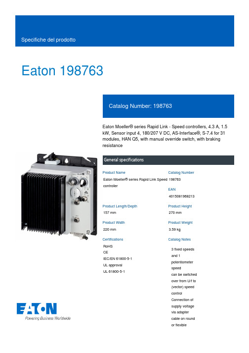
Eaton 198763Eaton Moeller® series Rapid Link - Speed controllers, 4.3 A, 1.5 kW, Sensor input 4, 180/207 V DC, AS-Interface®, S-7.4 for 31 modules, HAN Q5, with manual override switch, with braking resistanceGeneral specificationsEaton Moeller® series Rapid Link Speed controller1987634015081968213157 mm 270 mm 220 mm 3.59 kg RoHS CEIEC/EN 61800-5-1 UL approval UL 61800-5-1Product NameCatalog NumberEANProduct Length/Depth Product Height Product Width Product Weight Certifications Catalog Notes 3 fixed speeds and 1 potentiometer speedcan be switched over from U/f to (vector) speed control Connection of supply voltage via adapter cable on round or flexibleRASP5-4401A31-512R100S1Parameterization: FieldbusDiagnostics and reset on device and via AS-Interface Parameterization: drivesConnectParameterization: drivesConnect mobile (App) Parameterization: KeypadKey switch position OFF/RESETPTC thermistor monitoringKey switch position HANDBreaking resistanceIGBT inverterManual override switchTwo sensor inputs through M12 sockets (max. 150 mA) for quick stop and interlocked manual operationBraking resistanceThermo-click with safe isolationPC connectionSelector switch (Positions: REV - OFF - FWD)Internal DC linkKey switch position AUTOControl unit3 fixed speeds4-quadrant operation possibleBrake chopper with braking resistance for dynamic braking1 potentiometer speedFor actuation of motors with mechanical brake IP65NEMA 121st and 2nd environments (according to EN 61800-3)IIISpeed controllerASIAS-Interface profile cable: S-7.4 for 31 modulesC2, C3: depending on the motor cable length, the connected load, and ambient conditions. External radio interference suppression filters (optional) may be necessary.C1: for conducted emissions only2000 VCenter-point earthed star network (TN-S network)AC voltagePhase-earthed AC supply systems are not permitted.Vertical15 g, Mechanical, According to IEC/EN 60068-2-27, 11 ms, Half-sinusoidal shock 11 ms, 1000 shocks per shaftResistance: 6 Hz, Amplitude 0.15 mmResistance: According to IEC/EN 60068-2-6Resistance: 10 - 150 Hz, Oscillation frequencyResistance: 57 Hz, Amplitude transition frequency on accelerationModel CodeFeatures Fitted with:FunctionsDegree of protectionElectromagnetic compatibilityOvervoltage categoryProduct categoryProtocolRadio interference classRated impulse withstand voltage (Uimp)System configuration typeMounting positionShock resistanceVibrationbusbar junctionDiagnostics andreset on deviceand via AS-Interfaceintegrated PTCthermistormonitoring andThermoclick withsafe isolationoptional: 4sensor inputswith M12-Yadapter forswitchover tocreep speedoptional: Fasterstop if external24 V failsTwo sensorinputs throughM12 sockets(max. 150 mA)for quick stopand interlockedmanualoperationwith AUTO -OFF/RESET -HAND keyswitcheswith selectorswitch REV -OFF - FWDAbove 1000 m with 1 % performance reduction per 100 m Max. 2000 m-10 °C40 °C-40 °C70 °C< 95 %, no condensationIn accordance with IEC/EN 501780.4 - 4.3 A, motor, main circuit Adjustable, motor, main circuit< 10 ms, Off-delay< 10 ms, On-delay98 % (η)4.1 A3.5 mA120 %Maximum of one time every 60 seconds380 V480 V380 - 480 V (-10 %/+10 %, at 50/60 Hz)Synchronous reluctance motorsPM and LSPM motorsSensorless vector control (SLV)BLDC motorsU/f control0 Hz500 HzAt 40 °CFor 60 s every 600 s6.5 AAltitudeAmbient operating temperature - min Ambient operating temperature - max Ambient storage temperature - min Ambient storage temperature - max Climatic proofing Current limitationDelay timeEfficiencyInput current ILN at 150% overload Leakage current at ground IPE - max Mains current distortionMains switch-on frequencyMains voltage - minMains voltage - maxMains voltage toleranceOperating modeOutput frequency - minOutput frequency - maxOverload currentOverload current IL at 150% overload45 Hz66 Hz4.3 A at 150% overload (at an operating frequency of 8 kHz and an ambient air temperature of +40 °C)1.5 kW400 V AC, 3-phase480 V AC, 3-phase0.1 Hz (Frequency resolution, setpoint value)200 %, IH, max. starting current (High Overload), For 2 seconds every 20 seconds, Power section50/60 Hz8 kHz, 4 - 32 kHz adjustable, fPWM, Power section, Main circuitCenter-point earthed star network (TN-S network)AC voltagePhase-earthed AC supply systems are not permitted.2 HP≤ 0.6 A (max. 6 A for 120 ms), Actuator for external motor brakeAdjustable to 100 % (I/Ie), DC - Main circuit≤ 30 % (I/Ie)280/207 V DC -15 % / +10 %, Actuator for external motor brake765 VDC10 kAType 1 coordination via the power bus' feeder unit, Main circuit180/207 V DC (external brake 50/60 Hz)24 V DC (-15 %/+20 %, external via AS-Interface® plug)AS-InterfacePlug type: HAN Q5Max. total power consumption from AS-Interface® power supply C2 ≤ 5 m, maximum motor cable length C1 ≤ 1 m, maximum motor cable length C3 ≤ 25 m, maximum motor cable lengthRated frequency - minRated frequency - maxRated operational current (Ie)Rated operational power at 380/400 V, 50 Hz, 3-phase Rated operational voltageResolutionStarting current - maxSupply frequencySwitching frequencySystem configuration type Assigned motor power at 460/480 V, 60 Hz, 3-phase Braking currentBraking torqueBraking voltageSwitch-on threshold for the braking transistorRated conditional short-circuit current (Iq)Short-circuit protection (external output circuits) Rated control voltage (Uc)Communication interfaceConnectionInterfacesCable lengthunit (30 V): 190 mASpecification: S-7.4 (AS-Interface®)Number of slave addresses: 31 (AS-Interface®)Meets the product standard's requirements.Meets the product standard's requirements.Meets the product standard's requirements.Meets the product standard's requirements.Meets the product standard's requirements.Does not apply, since the entire switchgear needs to be evaluated.Does not apply, since the entire switchgear needs to be evaluated.Meets the product standard's requirements.Does not apply, since the entire switchgear needs to be evaluated.Meets the product standard's requirements.Does not apply, since the entire switchgear needs to be evaluated.Does not apply, since the entire switchgear needs to be evaluated.Is the panel builder's responsibility.Is the panel builder's responsibility.Is the panel builder's responsibility.Is the panel builder's responsibility.10.2.2 Corrosion resistance10.2.3.1 Verification of thermal stability of enclosures 10.2.3.2 Verification of resistance of insulating materials to normal heat10.2.3.3 Resist. of insul. mat. to abnormal heat/fire by internal elect. effects10.2.4 Resistance to ultra-violet (UV) radiation 10.2.5 Lifting10.2.6 Mechanical impact10.2.7 Inscriptions10.3 Degree of protection of assemblies10.4 Clearances and creepage distances 10.5 Protection against electric shock10.6 Incorporation of switching devices and components 10.7 Internal electrical circuits and connections 10.8 Connections for external conductors 10.9.2 Power-frequency electric strength 10.9.3 Impulse withstand voltageIs the panel builder's responsibility.The panel builder is responsible for the temperature rise calculation. Eaton will provide heat dissipation data for the devices.Is the panel builder's responsibility. The specifications for the switchgear must be observed.Is the panel builder's responsibility. The specifications for the switchgear must be observed.The device meets the requirements, provided the information in the instruction leaflet (IL) is observed.Rapid Link 5 - brochureDA-SW-USB Driver PC Cable DX-CBL-PC-1M5DA-SW-USB Driver DX-COM-STICK3-KITDA-SW-drivesConnect - installation helpDA-SW-Driver DX-CBL-PC-3M0DA-SW-drivesConnect - InstallationshilfeDA-SW-drivesConnectMaterial handling applications - airports, warehouses and intra-logisticseaton-bus-adapter-rapidlink-speed-controller-dimensions-003.eps eaton-bus-adapter-rapidlink-speed-controller-dimensions-004.eps eaton-bus-adapter-rapidlink-speed-controller-dimensions-002.eps eaton-bus-adapter-rapidlink-speed-controller-dimensions-005.epsETN.RASP5-4401A31-512R100S1.edzIL034085ZUramo5_v20.dwgrasp5_v20.stpConfiguration to Rockwell PLC for Rapid LinkGeneration change from RA-SP to RASP 4.0Generation Change RA-SP to RASP5Generation Change RASP4 to RASP5Generation change from RA-MO to RAMO 4.0Generation change RAMO4 to RAMO5DA-DC-00004508.pdfDA-DC-00003964.pdfDA-DC-00004514.pdfDA-DC-00004184.pdf10.9.4 Testing of enclosures made of insulating material10.10 Temperature rise10.11 Short-circuit rating10.12 Electromagnetic compatibility 10.13 Mechanical function BrochureDisegnieCAD modelIstruzioni di installazione mCAD modelNote per l'applicazione Report di certificazioneEaton Corporation plc Eaton House30 Pembroke Road Dublin 4, Ireland © 2023 Eaton. Tutti i diritti riservati. Eaton is a registered trademark.All other trademarks areproperty of their respectiveowners./socialmedia。
ZJT-45KW风机变频器使用说明书
目录1概述............................................................................................................................................................ - 1 -1.1主要特点 (1)1.1.1自动化程度高.............................................................................................................................. - 1 -1.1.2主要元部件品质高...................................................................................................................... - 1 -1.1.3直观清晰的液晶显示屏.............................................................................................................. - 1 -1.1.4系统运转稳定可靠...................................................................................................................... - 1 -1.1.5安全性.......................................................................................................................................... - 1 -1.2用途及功能 (1)1.2.1掘进工作面实现最大效率安全排放瓦斯 .................................................................................. - 2 -1.2.2采煤工作面限量抽排瓦斯形成安全可控的引排系统 .............................................................. - 2 -1.2.3节能运行...................................................................................................................................... - 2 -1.2.4正反转切换功能.......................................................................................................................... - 2 -1.2.6闭锁接口功能.............................................................................................................................. - 2 -1.2.7手动控制功能.............................................................................................................................. - 2 -1.2.8报警故障诊断功能...................................................................................................................... - 3 -1.2.9人性化的显示和输入设定功能.................................................................................................. - 3 -1.3型号的组成及代表意义 (4)1.4使用环境条件 (4)1.5工作条件 (4)1.6安全性 (4)2工作原理图结构特征 ................................................................................................................................ - 5 -2.1电气原图 (5)2.2结构特征 (5)2.3技术特征 (6)3安装和接线 ................................................................................................................................................ - 7 -3.1安装布置 (7)3.2接线 (9)4 操作和维护 ............................................................................................................................................. - 10 -4.1系统运行和参数详解 (10)4.2系统参数设置 (12)4.3调速装置的安装、使用、维护保养注意事项 (21)5 故障分析与排除 ..................................................................................................................................... - 21 -6运输与储存 .............................................................................................................................................. - 23 -7开箱及检查 .............................................................................................................................................. - 23 -煤炭科学研究总院重庆研究院执行标准:GB3836-2000 Q/MKC 27—2009版本:1.1日期:2010.12.1局部通风机双电源双变频调速装置使用说明书ZJT-45/660矿用隔爆兼本质安全型风机自动调速装置使用说明书1概述矿用隔爆兼本质安全型风机自动调速装置(以下简称调速装置)是由变频调速器和自动控制系统组成,外接瓦斯浓度传感器和主、备局部通风机。
- 1、下载文档前请自行甄别文档内容的完整性,平台不提供额外的编辑、内容补充、找答案等附加服务。
- 2、"仅部分预览"的文档,不可在线预览部分如存在完整性等问题,可反馈申请退款(可完整预览的文档不适用该条件!)。
- 3、如文档侵犯您的权益,请联系客服反馈,我们会尽快为您处理(人工客服工作时间:9:00-18:30)。
电脑控制器使用说明
电脑控制器主要功能有监视压缩机运行状态,控制压缩机,保护压缩机,监控保养零件等。
电脑控制器是空压机的控制核心,对机组正常运行起关键作用,故请用户使用前详细阅读本控制器使用说明。
一、基本操作
1、按键说明
排气温度:80C
供压:0.60MPa
运行状态:设备已停止
0秒机旁
ON M
图1
ON——起动键:按此键可起动电机运行
OFF——停机键:按此键可停止电机运行
M——设定键:修改完数据后,按此键确认数据存储输入
——上移键:数据修改时,按此键上翻修改该数位;在菜单选择时作为选择键。
——下移键:数据修改时,按此键下翻修改该数位;在菜单选择时作为选择键。
——移位键/确认键:修改数据时,此键作为移位键;在菜单选择时作为确定键。
RT——返回键/复位键:在菜单操作时作为返回键返回上一级菜单;故障停机时,按此键复位。
2、状态显示与操作
欢迎使用
*****杆压缩机
5秒后显示以下主界面:
排气温度:20℃
供气压力:
运行状态:设备已停止
按“”进入以下菜单选择界面:
运行参数
日历
用户参数
厂家参数
a、运行参数查看
按“”或“”移动黑色滚动条到“运行参数”菜单后,按确认键“”后弹出下一级菜单:
主、风机电流
运行总时间
本次运行时间
维护参数
再按“”弹出
电流(A):R S
T
主机:
风机:
如为最后一级菜单,界面不会出现黑色滚动条,按返回键“RT”返回上级菜单或主界面。
如在某一界面停止操作,数秒钟后自动返回主界面。
用“”、“”移动键、确认键“”和返回键“RT”根据上述方法可完全观察到运行时间、本次运行时间、维护参数、历史故障、出厂日期、现场故障等运行参数并返回到上级菜单。
b、日历时间
按“”或“”移动黑色滚动条到“日历”菜单后,按确认键“”后弹出
现行时间
2004年2月22日
星期0
12时46分59秒
在停机状态下可对日期、时间进行调整,操作方法为:
按“”或“”移动黑色滚动条到需修改的参数项后按确定键“”后出现闪烁位,此时“”和“”键变为上翻和下翻键修改当前位,“”变为移位键移动修改位。
修改完毕后按“M”确认并保存,“”或“”变回移动黑色滚动条,“”变回返回键。
c、用户参数
1)、参数修改方法
══在运行状态和停机延时过程中不能修改用户参数和厂家参数══
用前述运行参数查看的方法可查看和修改用户参数,如修改压力上限,操作方法如下:
按“”或“”移动黑色滚动条到“用户参数”项后按确定键“”弹出
再按确定键 “”弹出
如不继续按确定键 “”即可查看用户参数。
再按确定键 “
”弹出如下界面要求输入用户密
码:
注:用户密码在用户参数里可修改
此界面弹出后,出现闪烁位,此时“” 和“”键变为上翻和下翻键修改当前位, “”变为移位键移动修改位,最后按“M ”确认输入。
弹出界面:
右上角有“*”提示,表示已进入用户参数设定状态。
“” 或“”变回移动黑色滚动条,“”变回确定键。
滚动条在“压力上限”处按确认
键“”,此时出现闪烁位,“” 和“”键变为上翻和下翻键修改当前位, “”变为移位键移动修改位,输入完毕按“M ”确认,闪烁位消失。
“” 或“”变回移动黑色滚动条,“”变回确定键可继续修改其它用户参数。
如不需修改其它参数,按“RT ”键返回上级菜单或主菜单。
用同样方法可修改其它用户参数。
压力、温度预置 启停延时预置 操作方式预置 联动参数预置
压力上限 压力下限
风机启动温度 80℃ 风机停机温度 70℃
输入密码
****
压力上限 * 压力下限 风机启动温度 80℃ 风机停机温度 70℃
2)用户参数及功能
二、功能及技术参数
1、开关量:9路开关量输入,10路继电器开关量输出;
2、模拟量:二路Pt100温度输入,二路4~20mA变送输入,两组三相电流输入(配套CT);
3、相序输入电压:三相380V;
4、控制器工作电源:220V、50Hz、20VA;
5、显示量程
a)、油温:—20~150℃;精度:±1℃。
b)、气温:—20~150℃;精度:±1℃。
c)、运行时间:0~999999小时。
d)、电流显示量程:0~999.9A。
e)、压力:0~。
精度;。
6、相序保护:当保护器检测到错相时,动作时间≤2s;
7、电机保护:本控制器对主电机和风扇电机均具有以上五种基本保护功能
①、堵转保护:起动结束后,当工作电流达到设定电流的四至八倍时,动作时间≤;
②、短路保护:只要检测电流达到设定电流的八倍以上时,动作时间≤;
③、缺相保护:当任何一相电源缺相时,动作时间≤2s;
④、不平衡保护:任何两相间电流相差60~75%时,动作时间≤5s;
⑤、过载反时限保护特性(时间单位为秒),见下表。
倍数=I实/I设定
当电机运行电流大于或等于设定电流的倍至倍时按下表的过载倍数及动作时间延时动作
表2、电机保护反时限曲线表
9、输出继电器触点容量:250V5A;触点寿命500000次;
10、电流显示误差小于%.;
11、RS—485通讯
三、预警与提示
(1)、文本显示器提示
①、空滤器预警指示
a、用开关信号检测预警
控制器通过检测空滤器压差开关动作在文本显示器上提示操作者“空滤器阻塞”。
b、设定空滤器使用时间预警
空滤器使用时间到,文本显示器上提示操作者“空滤器使用时间到”。
②、油滤器预警指示
a、用开关信号检测预警
控制器通过检测油滤器压差开关动作在文本显示器上提示操作者“空滤器阻塞”。
b、设定油滤器使用时间预警
空滤器使用时间到,文本显示器上提示操作者“油滤器使用时间到”。
③、油分器预警指示
a、用开关信号检测预警
控制器通过检测油分器压差开关动作在文本显示器上提示操作者“油分器阻塞”。
b、设定油分器使用时间预警
空滤器使用时间到,文本显示器上提示操作者“油分器使用时间到”。
④、润滑油预警指示
润滑油使用时间到,文本显示器上提示操作者“润滑油使用时间到”
⑤、润滑脂预警指示
润滑脂使用时间到,文本显示器上提示操作者“润滑脂使用时间到”
(2)、主控器提示
四、安全保护
①、对电机的保护
MAM—KY02S空压机控制器对电机具有短路、堵转、过载、缺相、不平衡进行保护。
电气故障 故障显示
引起原因
短路 现场故障显示“主机或风机短路” 有短路产生或额定电流设定错误 堵转 现场故障显示“主机或风机堵转” 负载过大、轴承磨损、其它机械故障
过载 现场故障显示“主机或风机过载” 负载过大、轴承磨损、其它机械故障
缺相 现场故障显示“主机或风机*相缺相” 电源、接触器、电机缺相 不平衡
现场故障显示“主机或风机电流不平
衡”
接触器接触不良、电机内部开环
②、排气超温保护
排气温度高于设定温度高限控制器报警停机,现场故障显示“排气温高”。
③、空压机防逆转保护
当接入空压机的三相电源相序与控制器设置不一样时,现场故障显示“相序错误”,控制器不能起动电机。
此时仅需任意交换两相电源线并看电机转向即可。
④、供压超压保护
排气压力高于设定的压力高限时控制器报警停机,现场故障显示“排气压力高”。
⑤、传感器失灵保护
当压力传感器或温度传感器断线时,控制器报警停机。
现场故障显示“**传感器失灵”。
⑥、联动保护
主机运行,排气温度已到风机启动温度,但风机未运行控制器报警停机,现场故障显示“风机未运行”。
五、常见故障的处理
由于控制器外部器件引起的故障停机可通过查询现场故障或历史故障查出故障原因,排除
外围故障。
具体方法如下:
按“” 或“”移动黑色滚动条到“运行参数”菜单后,按确认键“”后弹出下一级
菜单:
一直按“”键弹出
按“”键如弹出如下故障原因:
主、风机电流 运行总时间 本次运行时间 维护参数 历史故障 出厂编号 现场故障 温度传感器失灵
此时主要检查温度传感器是否断线,传感器是否损坏等。
常见故障及原因:。