高斯计LZ-640 使用手册 英文 版
LEXMARK T640, T642, T644 说明书

第 4 章: 安装和移除选件 ........................................................................................25
安装输入选件 ................................................................................................................................................ 25 安装双面打印部件 ......................................................................................................................................... 27 安装内存或选件卡 ......................................................................................................................................... 28 进入打印机系统板 ......................................................................................................................................... 28 安装或移除内存卡 ......................................................................................................................................... 30 安装或移除闪烁存储器或固件卡 .................................................................................................................... 32 安装选件卡 .................................................................................................................................................... 34 重新安装挡板 ................................................................................................................................................ 35
640说明书 中文版

4
用户手册
5
保修卡
6
合格证
数量 1 1 1 1 1 1
单位 台 个 块 份 份 份
注:收到仪器后,请及时开箱对照以上清单核对物品数目,如有物品短缺或损坏请及时与湖 南省联众科技有限公司联系。
10
Copyright © 2000 - 2010 Linkjoin
【以下情况不属免费保修范围】 1. 霍尔探头属易损件,不在免费保修范围之列。 2. 因人为不慎或错误使用导致零部件缺损, 不在免费保修范围之列; 3. 用户在未经厂家授权的情况下,自行拆卸设备或更换零部件而造成设备无法正常使用的, 不在 免费保修范围之列; 4. 因不可抗拒外力造成设备无法正常使用(如水灾、火灾及台风等自然灾害及意外事故等), 不 在免费保修范围之列; 5. 因用户运输、使用、保管不当导致设备无法正常使用(包括受潮、腐蚀霉烂、机械损伤等),不 在免费保修范围之列。
6
Copyright © 2000 - 2010 Linkjoin
用户手册
第四章、仪器操作说明
1 操作步骤
1.) 打开仪器后部的电池盖,把 9V 的电池装入仪器后的电池槽里并盖好后盖。 2.) 将霍尔探头和主机连接好。探头(4)和主机下端的接口(4)均为五芯,连接时注意两接口要吻合
三、技术参数
9 工作电压 9 显示表头 9 量程范围 9 精确度 9 最小分辨率 9 测量磁场类型 9 极性判断 9 调零方式 9 使用环境 9 外形尺寸
9V 叠层电池 3_1/2 数显 200mT,2000mT 1% 0.1mT 直流 显示屏会有 N S 极性显示 手动(电位器调节) 温度-10°C~40°C,湿度:35~75% 150×70×25mm(长×宽×高)
ATMEGA640V资料

Features•High Performance, Low Power AVR® 8-Bit Microcontroller •Advanced RISC Architecture–135 Powerful Instructions – Most Single Clock Cycle Execution –32 x 8 General Purpose Working Registers–Fully Static Operation–Up to 16 MIPS Throughput at 16 MHz–On-Chip 2-cycle Multiplier•Non-volatile Program and Data Memories–64K/128K/256K Bytes of In-System Self-Programmable FlashEndurance: 10,000 Write/Erase Cycles–Optional Boot Code Section with Independent Lock BitsIn-System Programming by On-chip Boot ProgramTrue Read-While-Write Operation–4K Bytes EEPROMEndurance: 100,000 Write/Erase Cycles–8K Bytes Internal SRAM–Up to 64K Bytes Optional External Memory Space–Programming Lock for Software Security•JTAG (IEEE std. 1149.1 compliant) Interface–Boundary-scan Capabilities According to the JTAG Standard–Extensive On-chip Debug Support–Programming of Flash, EEPROM, Fuses, and Lock Bits through the JTAG Interface •Peripheral Features–Two 8-bit Timer/Counters with Separate Prescaler and Compare Mode–Four 16-bit Timer/Counter with Separate Prescaler, Compare- and Capture Mode –Real Time Counter with Separate Oscillator–Four 8-bit PWM Channels–Six/Twelve PWM Channels with Programmable Resolution from 2 to 16 Bits(ATmega1281/2561, ATmega640/1280/2560)–Output Compare Modulator–8/16-channel, 10-bit ADC (ATmega1281/2561, ATmega640/1280/2560)–Two/Four Programmable Serial USART (ATmega1281/2561,ATmega640/1280/2560)–Master/Slave SPI Serial Interface–Byte Oriented 2-wire Serial Interface–Programmable Watchdog Timer with Separate On-chip Oscillator–On-chip Analog Comparator–Interrupt and Wake-up on Pin Change•Special Microcontroller Features–Power-on Reset and Programmable Brown-out Detection–Internal Calibrated Oscillator–External and Internal Interrupt Sources–Six Sleep Modes: Idle, ADC Noise Reduction, Power-save, Power-down, Standby, and Extended Standby•I/O and Packages–54/86 Programmable I/O Lines (ATmega1281/2561, ATmega640/1280/2560)–64-pad QFN/MLF, 64-lead TQFP (ATmega1281/2561)–100-lead TQFP, 100-ball CBGA (ATmega640/1280/2560)–RoHS/Fully Green•Temperature Range:–-40°C to 85°C Industrial•Ultra-Low Power Consumption–Active Mode: 1 MHz, 1.8V: 510 µA–Power-down Mode: 0.1 µA at 1.8V•Speed Grade (see “Maximum speed vs. VCC” on page 377):–ATmega640V/ATmega1280V/ATmega1281V:0 - 4 MHz @ 1.8 - 5.5V, 0 - 8 MHz @ 2.7 - 5.5V–ATmega2560V/ATmega2561V:0 - 2 MHz @ 1.8 - 5.5V, 0 - 8 MHz @ 2.7 - 5.5V–ATmega640/ATmega1280/ATmega1281:0 - 8 MHz @ 2.7 - 5.5V, 0 - 16 MHz @ 4.5 - 5.5V–ATmega2560/ATmega2561:0 - 16 MHz @ 4.5 - 5.5V 8-bit Microcontroller64K/128K/256K Bytes In-System ProgrammableATmega640/V ATmega1280/V ATmega1281/V2ATmega640/1280/1281/2560/25612549KS–AVR–01/07Pin ConfigurationsFigure 1. TQFP-pinout ATmega640/1280/25603ATmega640/1280/1281/2560/25612549KS–AVR–01/07Figure 2. CBGA-pinout ATmega640/1280/2560Table 1. CBGA-pinout ATmega640/1280/2560.12345678910A G N D AREF PF0PF2PF5PK0PK3PK6G N D VCC B AVCC PG5PF1PF3PF6PK1PK4PK7PA0PA2C PE2PE0PE1PF4PF7PK2PK5PJ7PA1PA3D PE3PE4PE5PE6PH2PA4PA5PA6PA7PG2E PE7PH0PH1PH3PH5PJ6PJ5PJ4PJ3PJ2F VCC PH4PH6PB0PL4PD1PJ1PJ0PC7G N D G G N D PB1PB2PB5PL2PD0PD5PC5PC6VCC H PB3PB4RESET PL1PL3PL7PD4PC4PC3PC2J PH7PG3PB6PL0XT AL2PL6PD3PC1PC0PG1KPB7PG4VCCG N DXT AL1PL5PD2PD6PD7PG04ATmega640/1280/1281/2560/25612549KS–AVR–01/07Figure 3. Pinout ATmega1281/2561N ote:The large center pad underneath the QF N /MLF package is made of metal and internally connected to G N D. It should be soldered or glued to the board to ensure good mechani-cal stability. If the center pad is left unconnected, the package might loosen from the board.DisclaimerTypical values contained in this datasheet are based on simulations and characteriza-tion of other AVR microcontrollers manufactured on the same process technology. Min.and Max values will be available after the device is characterized.5ATmega640/1280/1281/2560/25612549KS–AVR–01/07OverviewThe ATmega640/1280/1281/2560/2561 is a low-power CMOS 8-bit microcontroller based on the AVR enhanced RISC architecture. By executing powerful instructions in a single clock cycle, the ATmega640/1280/1281/2560/2561 achieves throughputs approaching 1 MIPS per MHz allowing the system designer to optimize power consumption versus processing speed.Block DiagramFigure 4. Block Diagram6ATmega640/1280/1281/2560/25612549KS–AVR–01/07The AVR core combines a rich instruction set with 32 general purpose working registers.All the 32 registers are directly connected to the Arithmetic Logic Unit (ALU), allowing two independent registers to be accessed in one single instruction executed in one clock cycle. The resulting architecture is more code efficient while achieving throughputs up to ten times faster than conventional CISC microcontrollers.The ATmega640/1280/1281/2560/2561 provides the following features: 64K/128K/256K bytes of In-System Programmable Flash with Read-W hile-W rite capabilities, 4K bytes EEPROM, 8K bytes SRAM, 54/86 general purpose I/O lines, 32 general purpose work-ing registers, Real Time Counter (RTC), six flexible Timer/Counters with compare modes and P W M, 4 USARTs, a byte oriented 2-wire Serial Interface, a 16-channel, 10-bit ADC with optional differential input stage with programmable gain, programmable W atchdog Timer with Internal Oscillator, an SPI serial port, IEEE std. 1149.1 compliant JTAG test interface, also used for accessing the On-chip Debug system and program-ming and six software selectable power saving modes. The Idle mode stops the CPU while allowing the SRAM, Timer/Counters, SPI port, and interrupt system to continue functioning. The Power-down mode saves the register contents but freezes the Oscilla-tor, disabling all other chip functions until the next interrupt or Hardware Reset. In Power-save mode, the asynchronous timer continues to run, allowing the user to main-tain a timer base while the rest of the device is sleeping. The ADC N oise Reduction mode stops the CPU and all I/O modules except Asynchronous Timer and ADC, to min-imize switching noise during ADC conversions. In Standby mode, the Crystal/Resonator Oscillator is running while the rest of the device is sleeping. This allows very fast start-up combined with low power consumption. In Extended Standby mode, both the main Oscillator and the Asynchronous Timer continue to run.The device is manufactured using Atmel’s high-density nonvolatile memory technology.The On-chip ISP Flash allows the program memory to be reprogrammed in-system through an SPI serial interface, by a conventional nonvolatile memory programmer, or by an On-chip Boot program running on the AVR core. The boot program can use any interface to download the application program in the application Flash memory. Soft-ware in the Boot Flash section will continue to run while the Application Flash section is updated, providing true Read-W hile-W rite operation. By combining an 8-bit RISC CPU with In-System Self-Programmable Flash on a monolithic chip, the Atmel ATmega640/1280/1281/2560/2561 is a powerful microcontroller that provides a highly flexible and cost effective solution to many embedded control applications.The ATmega640/1280/1281/2560/2561 AVR is supported with a full suite of program and system development tools including: C compilers, macro assemblers, program debugger/simulators, in-circuit emulators, and evaluation kits.7ATmega640/1280/1281/2560/25612549KS–AVR–01/07Comparison Between ATmega1281/2561 and ATmega640/1280/2560Each device in the ATmega640/1280/1281/2560/2561 family differs only in memory size and number of pins. Table 2 summarizes the different configurations for the six devices.Pin DescriptionsVCC Digital supply voltage.GNDGround.Port A (PA7..PA0)Port A is an 8-bit bi-directional I/O port with internal pull-up resistors (selected for each bit). The Port A output buffers have symmetrical drive characteristics with both high sink and source capability. As inputs, Port A pins that are externally pulled low will source current if the pull-up resistors are activated. The Port A pins are tri-stated when a reset condition becomes active, even if the clock is not running.P o r t A a l s o s e r v e s t h e f u n c t i o n s o f v a r i o u s s p e c i a l f e a t u r e s o f t h e ATmega640/1280/1281/2560/2561 as listed on page 91.Port B (PB7..PB0)Port B is an 8-bit bi-directional I/O port with internal pull-up resistors (selected for each bit). The Port B output buffers have symmetrical drive characteristics with both high sink and source capability. As inputs, Port B pins that are externally pulled low will source current if the pull-up resistors are activated. The Port B pins are tri-stated when a reset condition becomes active, even if the clock is not running.Port B has better driving capabilities than the other ports.P o r t B a l s o s e r v e s t h e f u n c t i o n s o f v a r i o u s s p e c i a l f e a t u r e s o f t h e ATmega640/1280/1281/2560/2561 as listed on page 92.Port C (PC7..PC0)Port C is an 8-bit bi-directional I/O port with internal pull-up resistors (selected for each bit). The Port C output buffers have symmetrical drive characteristics with both high sink and source capability. As inputs, Port C pins that are externally pulled low will source current if the pull-up resistors are activated. The Port C pins are tri-stated when a reset condition becomes active, even if the clock is not running.P o r t C a l s o s e r v e s t h e f u n c t i o n s o f s p e c i a l f e a t u r e s o f t h e ATmega640/1280/1281/2560/2561 as listed on page 95.Port D (PD7..PD0)Port D is an 8-bit bi-directional I/O port with internal pull-up resistors (selected for each bit). The Port D output buffers have symmetrical drive characteristics with both high sink and source capability. As inputs, Port D pins that are externally pulled low will sourceTable 2. Configuration SummaryDevice Flash EEPROM RAM GeneralPurpose I/O pins16 bits resolution PWM channelsSerial USARTsADC ChannelsA Tmega64064KB 4KB 8KB 8612416A Tmega1280128KB 4KB 8KB 8612416A Tmega1281128KB 4KB 8KB 54628A Tmega2560256KB 4KB 8KB 8612416A Tmega2561256KB4KB8KB546288ATmega640/1280/1281/2560/25612549KS–AVR–01/07current if the pull-up resistors are activated. The Port D pins are tri-stated when a reset condition becomes active, even if the clock is not running.P o r t D a l s o s e r v e s t h e f u n c t i o n s o f v a r i o u s s p e c i a l f e a t u r e s o f t h e ATmega640/1280/1281/2560/2561 as listed on page 97.Port E (PE7..PE0)Port E is an 8-bit bi-directional I/O port with internal pull-up resistors (selected for each bit). The Port E output buffers have symmetrical drive characteristics with both high sink and source capability. As inputs, Port E pins that are externally pulled low will source current if the pull-up resistors are activated. The Port E pins are tri-stated when a reset condition becomes active, even if the clock is not running.P o r t E a l s o s e r v e s t h e f u n c t i o n s o f v a r i o u s s p e c i a l f e a t u r e s o f t h e ATmega640/1280/1281/2560/2561 as listed on page 99.Port F (PF7..PF0)Port F serves as analog inputs to the A/D Converter.Port F also serves as an 8-bit bi-directional I/O port, if the A/D Converter is not used.Port pins can provide internal pull-up resistors (selected for each bit). The Port F output buffers have symmetrical drive characteristics with both high sink and source capability.As inputs, Port F pins that are externally pulled low will source current if the pull-up resistors are activated. The Port F pins are tri-stated when a reset condition becomes active, even if the clock is not running. If the JTAG interface is enabled, the pull-up resis-tors on pins PF7(TDI), PF5(TMS), and PF4(TCK) will be activated even if a reset occurs.Port F also serves the functions of the JTAG interface.Port G (PG5..PG0)Port G is a 6-bit I/O port with internal pull-up resistors (selected for each bit). The Port G output buffers have symmetrical drive characteristics with both high sink and source capability. As inputs, Port G pins that are externally pulled low will source current if the pull-up resistors are activated. The Port G pins are tri-stated when a reset condition becomes active, even if the clock is not running.P o r t G a l s o s e r v e s t h e f u n c t i o n s o f v a r i o u s s p e c i a l f e a t u r e s o f t h e ATmega640/1280/1281/2560/2561 as listed on page 105.Port H (PH7..PH0)Port H is a 8-bit bi-directional I/O port with internal pull-up resistors (selected for each bit). The Port H output buffers have symmetrical drive characteristics with both high sink and source capability. As inputs, Port H pins that are externally pulled low will source current if the pull-up resistors are activated. The Port H pins are tri-stated when a reset condition becomes active, even if the clock is not running.P o r t H a l s o s e r v e s t h e f u n c t i o n s o f v a r i o u s s p e c i a l f e a t u r e s o f t h e ATmega640/1280/2560 as listed on page 107.Port J (PJ7..PJ0)Port J is a 8-bit bi-directional I/O port with internal pull-up resistors (selected for each bit). The Port J output buffers have symmetrical drive characteristics with both high sink and source capability. As inputs, Port J pins that are externally pulled low will source current if the pull-up resistors are activated. The Port J pins are tri-stated when a reset condition becomes active, even if the clock is not running.P o r t J a l s o s e r v e s t h e f u n c t i o n s o f v a r i o u s s p e c i a l f e a t u r e s o f t h e ATmega640/1280/2560 as listed on page 109.Port K (PK7..PK0)Port K serves as analog inputs to the A/D Converter.9ATmega640/1280/1281/2560/25612549KS–AVR–01/07Port K is a 8-bit bi-directional I/O port with internal pull-up resistors (selected for each bit). The Port K output buffers have symmetrical drive characteristics with both high sink and source capability. As inputs, Port K pins that are externally pulled low will source current if the pull-up resistors are activated. The Port K pins are tri-stated when a reset condition becomes active, even if the clock is not running.P o r t K a l s o s e r v e s t h e f u n c t i o n s o f v a r i o u s s p e c i a l f e a t u r e s o f t h e ATmega640/1280/2560 as listed on page 111.Port L (PL7..PL0)Port L is a 8-bit bi-directional I/O port with internal pull-up resistors (selected for each bit). The Port L output buffers have symmetrical drive characteristics with both high sink and source capability. As inputs, Port L pins that are externally pulled low will source current if the pull-up resistors are activated. The Port L pins are tri-stated when a reset condition becomes active, even if the clock is not running.P o r t L a l s o s e r v e s t h e f u n c t i o n s o f v a r i o u s s p e c i a l f e a t u r e s o f t h e ATmega640/1280/2560 as listed on page 113.Reset input. A low level on this pin for longer than the minimum pulse length will gener-ate a reset, even if the clock is not running. The minimum pulse length is given in Table 26 on page 58. Shorter pulses are not guaranteed to generate a reset.XTAL1Input to the inverting Oscillator amplifier and input to the internal clock operating circuit.XTAL2Output from the inverting Oscillator amplifier.AVCCAVCC is the supply voltage pin for Port F and the A/D Converter. It should be externally connected to V CC , even if the ADC is not used. If the ADC is used, it should be con-nected to V CC through a low-pass filter.AREFThis is the analog reference pin for the A/D Converter.ResourcesA comprehensive set of development tools and application notes, and datasheets are available for download on /avr.10ATmega640/1280/1281/2560/25612549KS–AVR–01/07Register SummaryAddressNameBit 7Bit 6Bit 5Bit 4Bit 3Bit 2Bit 1Bit 0Page(0x1FF)Reserved --------...Reserved --------(0x13F)Reserved (0x13E)Reserved (0x13D)Reserved (0x13C)Reserved (0x13B)Reserved (0x13A)Reserved (0x139)Reserved (0x138)Reserved (0x137)Reserved (0x136)UDR3 USART3 I/O Data Registerpage 227(0x135)UBRR3H ----USART3 Baud Rate Register High Bytepage 231(0x134)UBRR3L USART3 Baud Rate Register Low Bytepage 231(0x133)Reserved --------(0x132)UCSR3C UMSEL31UMSEL30UPM31UPM30USBS3UCSZ31UCSZ30UCPOL3page 244(0x131)UCSR3B RXCIE3TXCIE3UDRIE3RXE N 3TXE N 3UCSZ32RXB83TXB83page 243(0x130)UCSR3A RXC3TXC3UDRE3FE3DOR3UPE3U2X3MPCM3page 242(0x12F)Reserved --------(0x12E)Reserved --------(0x12D)OCR5CH Timer/Counter5 - Output Compare Register C High Byte page 167(0x12C)OCR5CL Timer/Counter5 - Output Compare Register C Low Byte page 167(0x12B)OCR5BH Timer/Counter5 - Output Compare Register B High Byte page 167(0x12A)OCR5BL Timer/Counter5 - Output Compare Register B Low Byte page 167(0x129)OCR5AH Timer/Counter5 - Output Compare Register A High Byte page 167(0x128)OCR5AL Timer/Counter5 - Output Compare Register A Low Byte page 167(0x127)ICR5H Timer/Counter5 - Input Capture Register High Byte page 168(0x126)ICR5L Timer/Counter5 - Input Capture Register Low Byte page 168(0x125)TC N T5H Timer/Counter5 - Counter Register High Byte page 165(0x124)TC N T5L Timer/Counter5 - Counter Register Low Bytepage 165(0x123)Reserved --------(0x122)TCCR5C FOC5A FOC5B FOC5C-----page 164(0x121)TCCR5B IC N C5ICES5-W GM53W GM52CS52CS51CS50page 162(0x120)TCCR5A COM5A1COM5A0COM5B1COM5B0COM5C1COM5C0W GM51W GM50page 160(0x11F)Reserved --------(0x11E)Reserved --------(0x11D)Reserved --------(0x11C)Reserved --------(0x11B)Reserved --------(0x11A)Reserved --------(0x119)Reserved --------(0x118)Reserved --------(0x117)Reserved --------(0x116)Reserved --------(0x115)Reserved --------(0x114)Reserved --------(0x113)Reserved --------(0x112)Reserved --------(0x111)Reserved --------(0x110)Reserved --------(0x10F)Reserved --------(0x10E)Reserved --------(0x10D)Reserved --------(0x10C)Reserved --------(0x10B)PORTL PORTL7PORTL6PORTL5PORTL4PORTL3PORTL2PORTL1PORTL0page 118(0x10A)DDRL DDL7DDL6DDL5DDL4DDL3DDL2DDL1DDL0page 118(0x109)PI N L PI N L7PI N L6PI N L5PI N L4PI N L3PI N L2PI N L1PI N L0page 118(0x108)PORTK PORTK7PORTK6PORTK5PORTK4PORTK3PORTK2PORTK1PORTK0page 118(0x107)DDRK DDK7DDK6DDK5DDK4DDK3DDK2DDK1DDK0page 118(0x106)PI N K PI N K7PI N K6PI N K5PI N K4PI N K3PI N K2PI N K1PI N K0page 118(0x105)PORTJ PORTJ7PORTJ6PORTJ5PORTJ4PORTJ3PORTJ2PORTJ1PORTJ0page 118(0x104)DDRJ DDJ7DDJ6DDJ5DDJ4DDJ3DDJ2DDJ1DDJ0page 118(0x103)PI N J PI N J7PI N J6PI N J5PI N J4PI N J3PI N J2PI N J1PI N J0page 118(0x102)PORTHPORTH7PORTH6PORTH5PORTH4PORTH3PORTH2PORTH1PORTH0page 117ATmega640/1280/1281/2560/2561Address Name Bit 7Bit 6Bit 5Bit 4Bit 3Bit 2Bit 1Bit 0Page(0x101)DDRH DDH7DDH6DDH5DDH4DDH3DDH2DDH1DDH0page 117(0x100)PI N H PI N H7PI N H6PI N H5PI N H4PI N H3PI N H2PI N H1PI N H0page 117 (0xFF)Reserved--------(0xFE)Reserved--------(0xFD)Reserved--------(0xFC)Reserved--------(0xFB)Reserved--------(0xFA)Reserved--------(0xF9)Reserved--------(0xF8)Reserved--------(0xF7)Reserved--------(0xF6)Reserved--------(0xF5)Reserved--------(0xF4)Reserved--------(0xF3)Reserved--------(0xF2)Reserved--------(0xF1)Reserved--------(0xF0)Reserved--------(0xEF)Reserved--------(0xEE)Reserved--------(0xED)Reserved--------(0xEC)Reserved--------(0xEB)Reserved-------(0xEA)Reserved--------(0xE9)Reserved--------(0xE8)Reserved--------(0xE7)Reserved-------(0xE6)Reserved--------(0xE5)Reserved--------(0xE4)Reserved--------(0xE3)Reserved-------(0xE2)Reserved--------(0xE1)Reserved-------(0xE0)Reserved-------(0xDF)Reserved--------(0xDE)Reserved--------(0xDD)Reserved-------(0xDC)Reserved--------(0xDB)Reserved--------(0xDA)Reserved--------(0xD9)Reserved-------(0xD8)Reserved--------(0xD7)Reserved--------(0xD6)UDR2 USART2 I/O Data Register page 227 (0xD5)UBRR2H----USART2 Baud Rate Register High Byte page 231 (0xD4)UBRR2L USART2 Baud Rate Register Low Byte page 231 (0xD3)Reserved--------(0xD2)UCSR2C UMSEL21UMSEL20UPM21UPM20USBS2UCSZ21UCSZ20UCPOL2page 244 (0xD1)UCSR2B RXCIE2TXCIE2UDRIE2RXE N2TXE N2UCSZ22RXB82TXB82page 243 (0xD0)UCSR2A RXC2TXC2UDRE2FE2DOR2UPE2U2X2MPCM2page 242 (0xCF)Reserved--------(0xCE)UDR1 USART1 I/O Data Register page 227 (0xCD)UBRR1H----USART1 Baud Rate Register High Byte page 231 (0xCC)UBRR1L USART1 Baud Rate Register Low Byte page 231 (0xCB)Reserved--------(0xCA)UCSR1C UMSEL11UMSEL10UPM11UPM10USBS1UCSZ11UCSZ10UCPOL1page 244 (0xC9)UCSR1B RXCIE1TXCIE1UDRIE1RXE N1TXE N1UCSZ12RXB81TXB81page 243 (0xC8)UCSR1A RXC1TXC1UDRE1FE1DOR1UPE1U2X1MPCM1page 242 (0xC7)Reserved--------(0xC6)UDR0 USART0 I/O Data Register page 227 (0xC5)UBRR0H----USART0 Baud Rate Register High Byte page 231 (0xC4)UBRR0L USART0 Baud Rate Register Low Byte page 231 (0xC3)Reserved--------(0xC2)UCSR0C UMSEL01UMSEL00UPM01UPM00USBS0UCSZ01UCSZ00UCPOL0page 244 (0xC1)UCSR0B RXCIE0TXCIE0UDRIE0RXE N0TXE N0UCSZ02RXB80TXB80page 243 (0xC0)UCSR0A RXC0TXC0UDRE0FE0DOR0UPE0U2X0MPCM0page 243Address Name Bit 7Bit 6Bit 5Bit 4Bit 3Bit 2Bit 1Bit 0Page (0xBF)Reserved--------(0xBE)Reserved--------(0xBD)T W AMR T W AM6T W AM5T W AM4T W AM3T W AM2T W AM1T W AM0-page 274 (0xBC)T W CR T W I N T T W EA T W STA T W STO T WW C T W E N-T W IE page 271 (0xBB)T W DR 2-wire Serial Interface Data Register page 273 (0xBA)T W AR T W A6T W A5T W A4T W A3T W A2T W A1T W A0T W GCE page 273 (0xB9)T W SR T W S7T W S6T W S5T W S4T W S3-T W PS1T W PS0page 272 (0xB8)T W BR2-wire Serial Interface Bit Rate Register page 271 (0xB7)Reserved--------(0xB6)ASSR-EXCLK AS2TC N2UB OCR2AUB OCR2BUB TCR2AUB TCR2BUB page 188 (0xB5)Reserved--------(0xB4)OCR2B Timer/Counter2 Output Compare Register B page 195 (0xB3)OCR2A Timer/Counter2 Output Compare Register A page 195 (0xB2)TC N T2 Timer/Counter2 (8 Bit)page 195 (0xB1)TCCR2B FOC2A FOC2B--W GM22CS22CS21CS20page 194 (0xB0)TCCR2A COM2A1COM2A0COM2B1COM2B0--W GM21W GM20page 195 (0xAF)Reserved--------(0xAE)Reserved--------(0xAD)OCR4CH Timer/Counter4 - Output Compare Register C High Byte page 167 (0xAC)OCR4CL Timer/Counter4 - Output Compare Register C Low Byte page 167 (0xAB)OCR4BH Timer/Counter4 - Output Compare Register B High Byte page 166 (0xAA)OCR4BL Timer/Counter4 - Output Compare Register B Low Byte page 166 (0xA9)OCR4AH Timer/Counter4 - Output Compare Register A High Byte page 166 (0xA8)OCR4AL Timer/Counter4 - Output Compare Register A Low Byte page 166 (0xA7)ICR4H Timer/Counter4 - Input Capture Register High Byte page 168 (0xA6)ICR4L Timer/Counter4 - Input Capture Register Low Byte page 168 (0xA5)TC N T4H Timer/Counter4 - Counter Register High Byte page 165 (0xA4)TC N T4L Timer/Counter4 - Counter Register Low Byte page 165 (0xA3)Reserved--------(0xA2)TCCR4C FOC4A FOC4B FOC4C-----page 164 (0xA1)TCCR4B IC N C4ICES4-W GM43W GM42CS42CS41CS40page 162 (0xA0)TCCR4A COM4A1COM4A0COM4B1COM4B0COM4C1COM4C0W GM41W GM40page 160 (0x9F)Reserved--------(0x9E)Reserved--------(0x9D)OCR3CH Timer/Counter3 - Output Compare Register C High Byte page 166 (0x9C)OCR3CL Timer/Counter3 - Output Compare Register C Low Byte page 166 (0x9B)OCR3BH Timer/Counter3 - Output Compare Register B High Byte page 166 (0x9A)OCR3BL Timer/Counter3 - Output Compare Register B Low Byte page 166 (0x99)OCR3AH Timer/Counter3 - Output Compare Register A High Byte page 166 (0x98)OCR3AL Timer/Counter3 - Output Compare Register A Low Byte page 166 (0x97)ICR3H Timer/Counter3 - Input Capture Register High Byte page 168 (0x96)ICR3L Timer/Counter3 - Input Capture Register Low Byte page 168 (0x95)TC N T3H Timer/Counter3 - Counter Register High Byte page 165 (0x94)TC N T3L Timer/Counter3 - Counter Register Low Byte page 165 (0x93)Reserved--------(0x92)TCCR3C FOC3A FOC3B FOC3C-----page 164 (0x91)TCCR3B IC N C3ICES3-W GM33W GM32CS32CS31CS30page 162 (0x90)TCCR3A COM3A1COM3A0COM3B1COM3B0COM3C1COM3C0W GM31W GM30page 160 (0x8F)Reserved--------(0x8E)Reserved--------(0x8D)OCR1CH Timer/Counter1 - Output Compare Register C High Byte page 166 (0x8C)OCR1CL Timer/Counter1 - Output Compare Register C Low Byte page 166 (0x8B)OCR1BH Timer/Counter1 - Output Compare Register B High Byte page 166 (0x8A)OCR1BL Timer/Counter1 - Output Compare Register B Low Byte page 166 (0x89)OCR1AH Timer/Counter1 - Output Compare Register A High Byte page 166 (0x88)OCR1AL Timer/Counter1 - Output Compare Register A Low Byte page 166 (0x87)ICR1H Timer/Counter1 - Input Capture Register High Byte page 168 (0x86)ICR1L Timer/Counter1 - Input Capture Register Low Byte page 168 (0x85)TC N T1H Timer/Counter1 - Counter Register High Byte page 165 (0x84)TC N T1L Timer/Counter1 - Counter Register Low Byte page 165 (0x83)Reserved--------(0x82)TCCR1C FOC1A FOC1B FOC1C-----page 164 (0x81)TCCR1B IC N C1ICES1-W GM13W GM12CS12CS11CS10page 162 (0x80)TCCR1A COM1A1COM1A0COM1B1COM1B0COM1C1COM1C0W GM11W GM10page 160 (0x7F)DIDR1------AI N1D AI N0D page 278 (0x7E)DIDR0ADC7D ADC6D ADC5D ADC4D ADC3D ADC2D ADC1D ADC0D page 300ATmega640/1280/1281/2560/2561Address Name Bit 7Bit 6Bit 5Bit 4Bit 3Bit 2Bit 1Bit 0Page (0x7D)DIDR2ADC15D ADC14D ADC13D ADC12D ADC11D ADC10D ADC9D ADC8D page 300 (0x7C)ADMUX REFS1REFS0ADLAR MUX4MUX3MUX2MUX1MUX0page 294 (0x7B)ADCSRB-ACME--MUX5ADTS2ADTS1ADTS0page 277,295,,299 (0x7A)ADCSRA ADE N ADSC ADATE ADIF ADIE ADPS2ADPS1ADPS0page 297 (0x79)ADCH ADC Data Register High byte page 298 (0x78)ADCL ADC Data Register Low byte page 298 (0x77)Reserved--------(0x76)Reserved--------(0x75)XMCRB XMBK----XMM2XMM1XMM0page 36 (0x74)XMCRA SRE SRL2SRL1SRL0SR W11SR W10SR W01SR W00page 34 (0x73)TIMSK5--ICIE5-OCIE5C OCIE5B OCIE5A TOIE5page 169 (0x72)TIMSK4--ICIE4-OCIE4C OCIE4B OCIE4A TOIE4page 169 (0x71)TIMSK3--ICIE3-OCIE3C OCIE3B OCIE3A TOIE3page 169 (0x70)TIMSK2-----OCIE2B OCIE2A TOIE2page 197 (0x6F)TIMSK1--ICIE1-OCIE1C OCIE1B OCIE1A TOIE1page 169 (0x6E)TIMSK0-----OCIE0B OCIE0A TOIE0page 135 (0x6D)PCMSK2PCI N T23PCI N T22PCI N T21PCI N T20PCI N T19PCI N T18PCI N T17PCI N T16page 81 (0x6C)PCMSK1PCI N T15PCI N T14PCI N T13PCI N T12PCI N T11PCI N T10PCI N T9PCI N T8page 81 (0x6B)PCMSK0PCI N T7PCI N T6PCI N T5PCI N T4PCI N T3PCI N T2PCI N T1PCI N T0page 82 (0x6A)EICRB ISC71ISC70ISC61ISC60ISC51ISC50ISC41ISC40page 79 (0x69)EICRA ISC31ISC30ISC21ISC20ISC11ISC10ISC01ISC00page 78 (0x68)PCICR-----PCIE2PCIE1PCIE0page 80 (0x67)Reserved--------(0x66)OSCCAL Oscillator Calibration Register page 48 (0x65)PRR1--PRTIM5PRTIM4PRTIM3PRUSART3PRUSART2PRUSART1page 56 (0x64)PRR0PRT W I PRTIM2PRTIM0-PRTIM1PRSPI PRUSART0PRADC page 55 (0x63)Reserved--------(0x62)Reserved--------(0x61)CLKPR CLKPCE---CLKPS3CLKPS2CLKPS1CLKPS0page 48 (0x60)W DTCSR W DIF W DIE W DP3W DCE W DE W DP2W DP1W DP0page 660x3F (0x5F)SREG I T H S V N Z C page 120x3E (0x5E)SPH SP15SP14SP13SP12SP11SP10SP9SP8page 140x3D (0x5D)SPL SP7SP6SP5SP4SP3SP2SP1SP0page 140x3C (0x5C)EI N D-------EI N D0page 150x3B (0x5B)RAMPZ------RAMPZ1RAMPZ0page 150x3A (0x5A)Reserved--------0x39 (0x59)Reserved--------0x38 (0x58)Reserved--------0x37 (0x57)SPMCSR SPMIE R WW SB SIGRD R WW SRE BLBSET PG W RT PGERS SPME N page 3400x36 (0x56)Reserved--------0x35 (0x55)MCUCR JTD--PUD--IVSEL IVCE page 66,76,115,3140x34 (0x54)MCUSR---JTRF W DRF BORF EXTRF PORF page 3140x33 (0x53)SMCR----SM2SM1SM0SE page 510x32 (0x52)Reserved--------0x31 (0x51)OCDR OCDR7OCDR6OCDR5OCDR4OCDR3OCDR2OCDR1OCDR0page 3070x30 (0x50)ACSR ACD ACBG ACO ACI ACIE ACIC ACIS1ACIS0page 2770x2F (0x4F)Reserved--------0x2E (0x4E)SPDR SPI Data Register page 2080x2D (0x4D)SPSR SPIF W COL-----SPI2X page 2070x2C (0x4C)SPCR SPIE SPE DORD MSTR CPOL CPHA SPR1SPR0page 2060x2B (0x4B)GPIOR2General Purpose I/O Register 2page 340x2A (0x4A)GPIOR1General Purpose I/O Register 1page 340x29 (0x49)Reserved--------0x28 (0x48)OCR0B Timer/Counter0 Output Compare Register B page 1340x27 (0x47)OCR0A Timer/Counter0 Output Compare Register A page 1340x26 (0x46)TC N T0 Timer/Counter0 (8 Bit)page 1340x25 (0x45)TCCR0B FOC0A FOC0B--W GM02CS02CS01CS00page 1330x24 (0x44)TCCR0A COM0A1COM0A0COM0B1COM0B0--W GM01W GM00page 1300x23 (0x43)GTCCR TSM-----PSRASY PSRSY N C page 173, 1980x22 (0x42)EEARH----EEPROM Address Register High Byte page 320x21 (0x41)EEARL EEPROM Address Register Low Byte page 320x20 (0x40)EEDR EEPROM Data Register page 320x1F (0x3F)EECR--EEPM1EEPM0EERIE EEMPE EEPE EERE page 320x1E (0x3E)GPIOR0General Purpose I/O Register 0page 340x1D (0x3D)EIMSK I N T7I N T6I N T5I N T4I N T3I N T2I N T1I N T0page 790x1C (0x3C)EIFR I N TF7I N TF6I N TF5I N TF4I N TF3I N TF2I N TF1I N TF0page 80。
利卡橄榄球640G 640快速指南版本4.0说明书

Leica Rugby 640G/640Quick GuideVersion 4.02Rugby 640G/640, Important Information about your Instrumenta) Stationary laser beamb) Rotating laser beamb bRugby 640G/640, Important Information about your Instrument3YXX+Y+Y—X—X+Y+Y—X—IO4Rugby 640G/640, Important Information about your Instrument 0 rps, 2 rps, 5 rps, 10 rpsX+Y+Y—X—X+Y+Y—X—YXIORugby 640G/640, Important Information about your Instrument5X+Y+Y—X—X+Y+Y—X—90°6Rugby 640G/640, Important Information about your Instrument Pairing=RC400 Remote Control4x D-cell (LR20)Li-IonAlkaline4x AA-cell (LR6)Rugby 640G/640, Important Information about your Instrument7Rod Eye 120/120G, Basic 0G , Ba sic8 Rugby 640G/640, Important Information about your Instrumentba6578 1 + 23Rugby 640G/640, Important Information about your Instrument 910Rugby 640G/640, Important Information about your Instrument 431 + 257a 7b7c1 + 23Xαα7baRugby 640G/640, Important Information about your Instrument1112Rugby 640G/640, Important Information about your Instrument 3241562413Rugby 640G/640, Important Information about your Instrument 1314 Rugby 640G/640, Important Information about your InstrumentConformity to national regula-tions •FCC Part 15, 22 and 24 (applicable in US)•Hereby, Leica Geosystems AG, declares that the Rugby 640G/640 is in compli-ance with the essential requirements and other relevant provisions of Directive 1999/5/EC and other applicable European Directives. The declaration ofconformity can be consulted at /ce.•This Class 2 equipment may be operated in: AT, BE, CY, CZ, DK, EE, FI, FR, DE, GR, HU, IE, IT, LV, LT, LU, MT, NL, PL, PT, SK, SI, ES, SE, GB, IS, LI, NO, CH, BG, RO and TR.Class 2 equipment according European Directive 1999/5/EC(R&TTE) for which following EEA Member States applyrestrictions on the placing on the market or on the puttinginto service or require authorisation for use:•France•Italy•Norway (if used in the geographical area within a radiusof 20km from the centre of Ny-Ålesund)•The conformity for countries with other national regulations not covered by the FCC part 15 or European directive 1999/5/EC has to be approved prior to use and operation.Rugby 640G/640, Important Information about your Instrument15RegulationsLithium batteries can be dangerous under certain conditions and can pose a safety hazard. In certain conditions, Lithium batteries can overheat and ignite.☞When carrying or shipping your Leica product with Lithium batteries onboard a commercial aircraft, you must do so in accordance with the IATA Dangerous Goods Regulations .☞Leica Geosystems has developed Guidelines on “How to carry Leica prod-ucts” and “How to ship Leica products” with Lithium batteries. Before any transportation of a Leica product, we ask you to consult these guidelines on our web page (/dgr) to ensure that you are in accordance with the IATA Dangerous Goods Regulations and that the Leica products can be transported correctly.☞Damaged or defective batteries are prohibited from being carried or trans-ported onboard any aircraft. Therefore, ensure that the condition of any battery is safe for transportation.•Japanese Radio Law and Japanese Telecommunications Business Law Compliance.–This device is granted pursuant to the Japanese Radio Law () and the Japanese Telecommunications Business Law ().–This device should not be modified (otherwise the granted designation number will become invalid).Leica Geosystems AG Heinrich-Wild-StrasseCH-9435 Heerbrugg SwitzerlandPhone +41 71 727 31 31 799992-4..enOriginaltextPrintedinSwitzerland©216LeicaGeosystemsAG,Heerbrugg,SwitzerlandLaser class 2 product in accordance with IEC 60825-1:2014。
Ecofit CPA640 120 mm Sensor Process Assembly 用户说明说
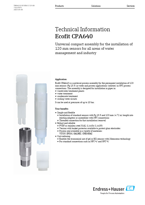
ApplicationEcofit CPA640 is a universal process assembly for the permanent installation of 120mm sensors (Pg 13.5) in water and process applications (utilities) in NPT process connections. The assembly is designed for installation in pipes in:•wastewater treatment plants •water treatment•condensate treatment •cooling water circuitsIt can be used at pressures of up to 10 bar.Your benefits•Simple and flexible•Installation of standard sensors with Pg 13.5 and 120 mm (4.72 in) length into existing adapters or assemblies with NPT connections •Threaded connection for fast installation/removal •Robust and reliable•PVDF or stainless steel 316L (1.4404/1.4435)•Version with basket protector available to protect glass electrodes •Process seal available in a variety of materials:VITON, EPDM, KALREZ, CHEMRAZ •Cost-reducing•Enables the economical use of gel or KCl sensors with Memosens technology •For standard connections such as NPT ½" and NPT ¾"Products Solutions ServicesTechnical Information Ecofit CPA640Universal compact assembly for the installation of 120 mm sensors for all areas of water management and industryTI00421C/07/EN/17.23-00716139752023-05-05Ecofit CPA6402Endress+HauserFunction and system designMeasuring systemA complete measuring system comprises:•Ecofit CPA640 installation adapter•Sensor with Pg 13.5, length 120 mm, e.g. Orbisint CPS11D •Transmitter, e.g. Liquiline CM42•Measuring cable, e.g. CYK101Measuring system with CPA640, transmitter (CM42), sensor and cable A Direct installation at NPT process connection B Installation in immersion assembly (CYA611)CInstallation in flow assemblyProcessPressure-temperature ratings2temperature/pressure ratings1Stainless steel 1.4404/1.4435 (AISI 316L), MONEL 2PVDFEcofit CPA640Mechanical construction3CPA640-A/B***. Unit of measurement mm (in)4CPA640-C/D***. Unit of measurement mm (in)Endress+Hauser3Ecofit CPA6405CPA640-E***. Unit of measurement mm (in)6CPA640-G/I***. Unit of measurement mm (in)Weight Approx. 0.1 to 0.3 kg (0.22 to 0.66 lbs) depending on the version4Endress+HauserEcofit CPA640Endress+Hauser 5MaterialsAdapter bodyCPA640-A/C/E/G***PVDF (polyvinylidenefluoride)CPA640-B/D***Stainless steel 316L (1.4404/14435))CPA640-I***MONEL Sealing ring FDM (VITON), EPDM, CHEMRAZ, KALREZEndress+Hauser supplies DIN/EN process connections with stainless steel threaded connection in accordance with AISI 316L (DIN/EN material number 1.4404 or 14435).In terms of their stability-temperature property, the materials 1.4404 and 1.4435 are grouped in EN 1092-1 table 18 under 13E0. The chemical composition of the two materials can be identical.Process connections•The assembly can only be installed if the process is unpressurized and the container is empty.•The assembly is designed for installation on containers or pipes.•Appropriate process connections must be provided for the installation.•Make sure the orientation is correct. Information can be found in the manual of the sensor used.Process connections depend on the assembly version:Assembly version Process connection CPA640-A/B***NPT ½"CPA640-C/D***NPT ¾"CPA640-E***NPT 1"CPA640-G/I***M25x1.5Ordering informationProduct page /cpa640Product Configurator1.Configure : Click this button on the product page.2.Select Extended selection .The Configurator opens in a separate window.3.Configure the device according to your requirements by selecting the desired option for each feature.In this way, you receive a valid and complete order code for the device.4.Apply : Add the configured product to the shopping cart.For many products, you also have the option of downloading CAD or 2D drawings of the selected product version.5.Show details : Open this tab for the product in the shopping cart.The link to the CAD drawing is displayed. If selected, the 3D display format is displayedalong with the option to download various formats.Scope of deliveryThe scope of delivery comprises:•Ordered version of assembly •Operating InstructionsEcofit CPA6406Endress+HauserCertificates and approvalsCurrent certificates and approvals for the product are available at on the relevant product page:1.Select the product using the filters and search field.2.Open the product page.3.Select Downloads .Ecofit CPA640Endress+Hauser 7AccessoriesThe following are the most important accessories available at the time this documentation was issued.Listed accessories are technically compatible with the product in the instructions.1.Application-specific restrictions of the product combination are possible.Ensure conformity of the measuring point to the application. This is the responsibility of the operator of the measuring point.2.Pay attention to the information in the instructions for all products, particularly the technical data.3.For accessories not listed here, please contact your Service or Sales Center.Sensors (selection)pH sensorsCeragel CPS71•pH electrode with reference system including ion trap•Product Configurator on the product page:/cps71Technical Information TI00245CMemosens CPS71E•pH sensor for chemical process applications •Digital with Memosens 2.0 technology•Product Configurator on the product page:/cps71eTechnical Information TI01496CCeraliquid CPS41•pH electrode with ceramic junction and KCl liquid electrolyte•Product Configurator on the product page:/cps41Technical Information TI00079CMemosens CPS41E•pH sensor for process technology•With ceramic junction and KCl liquid electrolyte •Digital with Memosens 2.0 technology•Product Configurator on the product page:/cps41eTechnical Information TI01495CMemosens CPS77E•Sterilizable and autoclavable ISFET sensor for pH measurement •Digital with Memosens 2.0 technology•Product Configurator on the product page:/cps77eTechnical Information TI01396ORP sensorsCeragel CPS72•ORP electrode with reference system including ion trap•Product Configurator on the product page:/cps72Technical Information TI00374CMemosens CPS72E•ORP sensor for chemical process applications •Digital with Memosens 2.0 technology•Product Configurator on the product page:/cps72eTechnical Information TI01576CEcofit CPA640Oxygen sensorsOxymax COS22•Sterilizable sensor for dissolved oxygen•With Memosens technology or as an analog sensor•Product Configurator on the product page:/cos22Technical Information TI00446CMemosens COS22E•Hygienic amperometric oxygen sensor with maximum measurement stability over multiple sterilization cycles•Digital with Memosens 2.0 technology•Product Configurator on the product page:/cos22eTechnical Information TI01619C*71613975*71613975。
Shure AXT600 频谱管理器用户手册说明书

AXT600 Spectrum ManagerManual for the Shure Axient Spectrum Manager (AXT600). Version: 4 (2019-L)Table of ContentsAXT600Spectrum Manager 3簡要 說明3特性 3前面板4後面板 5連接天線6安裝說明6主功能表螢幕6資料顯示螢幕 8頻譜管理器與接收機的連網8自動 IP 地址分配 9手動 IP 地址 9設備重置 9故障排除 9網路存取控制 10 RF 協調精靈10 All New 10 Update Freqs 10 Update Devices 10使用 All New 精靈選項進行系統設定11排除12輸入排除項目 12事件日誌12頻譜監控13備用頻率監控 13 Listen 13掃描 14設定風扇速度15韌件更新15規格15掃描時間 17 RF 輸入 17連網 18附件18提供的附件 18 Information to the user19重要安全事項! 19適用於所有耳筒的警告! 20警告 21認證21AXT600Spectrum Manager 簡要 說明Axient 頻譜管理器是一款功能強大的工具,它能夠為無線元件計算、分析並分配相容頻率。
頻譜管理器掃描 RF 環境,並使用獲得的資料為在網路中發現的所有無線頻道計算相容頻率。
可以從“相容頻率列表”中對已連網的無線系統進行編程,並且可以持續監控備用頻率,並根據訊號質量對頻率進行分級。
在使用過程中,頻譜管理器可以在發生干擾時將清晰的頻率分配給接收機。
內置的頻譜監控工具能夠提供對 RF 活動的可視化和音訊跟蹤。
特性帶寬掃描頻率管理器能夠在可用於無線音訊的整個 UHF 頻率範圍內掃描資料。
掃描過程使用兩組天線輸入完成,這兩組天線都具有直接適用於無線接收機的敏感度和解析能力。
相容頻率列表相容頻率列表 (CFL) 是一個可用頻率的列表,可通過頻譜管理器進行計算、查看及編輯或可從運行 Wireless Workbench 6 的電腦上生成。
Roland VersaEXPRESS RF-640 大型格式打印机商品说明书

VERSAEXPRESS RF-64064” LARGE FORMAT PrinterPure genius.The V ersaEXPRESS RF-640Productivity and reliability at a smart price.The Roland VersaEXPRESS™ RF-640 offers the perfect formula for digital printing success: high production speed, outstanding print quality, ease of use and unsurpassed reliability. The genius behind the RF-640 is reflected in its ability to quickly produce high quality graphics and prints, while keeping cost of operation low. That translates into increased output, satisfied customers and more money in your pocket.Advanced Productivity FeaturesEquipped with advanced productivity features, the RF-640 is ideal for any high production environment. It boasts advanced print control technology for quality imaging and color consistency, while adjustable media support brackets to handle narrow or wide rolls with equal ease. The innovative Roland Ink Switching System adds greater production capability by automatically switching from an empty 440 ml cartidge to a back-up cartridge when ink runs out, allowing you to change out cartridges right from the front of the machine without having to stop and restart the printer. Workflow and output are further enhanced by Roland’s user-friendly V ersaWorks® RIP software, which includes media profiles, nesting, cropping, predictive ink and media usage, and other powerful production tools. V ersaWorks also features built-in Roland Color System and PANTONE® libraries for easy and accurate color spot matching.State of the Art Print T echnologySpecially designed to take full advantage of Roland’s high-density, GREENGUARD Gold Certified UL 2818 Eco-Sol MAX® 2 inks, the RF-640 prints beautiful, saturated color with virtually no banding – even at higher speeds. A mirrored CMYKKYMC gold-plated print head firing seven different droplet sizes ensures stunning graphic results on a wide range of media at speeds up to 521 square feet per hour. Roland Intelligent Pass Control™ further enhances image quality by minimizing any trace of bleeding and ensuring precise media feeding between passes.T o learn more about the pure genius of the RF, view thevideo at /rf.Intelligent ImagingDelivers smooth gradations, high-fidelity images and flawless solid colorsRoland Printer Assist iPad appRemotely manage production, test printing, cleaning and moreThe Genius of SimplicityY ou don’t have to be a genius to use an RF-640. In fact, this printer’s innovative features and technological advancements make it incredibly easy to operate. With the Roland Printer Assist iPad app, you can even remotely manage production, test printing, and even cleaning functions from an iPad tablet. Additional features for increased ease of use and convenience include an easy-access front-loading ink cartridge system, media loading levers at both the front and back of the printer, and a take-up unit that supports media rolls up to 110 lbs.Smart SavingsThe RF-640’s design allows for low running costs and easy maintenance. Precise inkjet technology and new optimized profiles for Eco-Sol MAX 2 ink work together for efficient ink consumption. An automated cleaning function also minimizes ink usage, while helping to prolong print head life. As a result, the RF-640 is highly efficient in both production and standby modes. As proof of its unmatched reliability, the RF-640 is backed by Roland’s unmatched T wo-Y ear Trouble-Free Warranty.**Registration within 60 days and continuous exclusive use of Roland inks during the first two years of ownership is required to qualify for the free second year of limited warranty coverage. Additional T erms and Conditions apply. See /warranties for details.Engineered to image beautifully,the RF offers a rare combination of value and performance, making it a very smart purchasing decision. Talk about genius!Specifications subject to change. *Outdoor durability is based on accelerated weather tests. Results may vary depending upon location and application. Lamination may be required for some applications or environmental conditions.Roland DGA Corp. has licensed the MMP technology from the TPL Group.FOR ADDITIONAL PRODUCT INFORMATION AND FEATURES, OR TO REQUEST A SAMPLE PRINT , CALL 800-542-2307 OR VISIT /RF ROLAND DGA CORPORATION | 15363 BARRANCA PARKWAY | IRVINE, CALIFORNIA 92618-2216 | 800.542.2307 | 949.727.2100 | CERTIFIED ISO 9001:2008RDGA-RF-01 July 2014VERSAEXPRESS™ RF-640 INKJET PRINTER• Large-format printer with 64” width, built to provideunsurpassed printing performance, even when unattended, in demanding production environments• 8-channel print head with mirrored CMYKKYMC configuration virtually eliminates chromatic banding • Photorealistic printing up to 1440 dpi• Roland Intelligent Pass Control™ technology• High density Eco-Sol MAX® 2 ink produces rich, vibrant colors on coated or uncoated media > Wide gamut for dynamic color imaging > Increased density for rich, saturated colors> Fast drying, virtually oderless, and scratch resistant > Up to three years outdoor durability without lamination* > GREENGUARD Gold certified• Automated TU-3 media take-up system > Supports extended production runs> Adjustable right flange for easy centering of smaller rolls • Integrated two-stage heating system supports high-speed, volume production• Automatic cleaning cycles simplify maintenance • Roland VersaWorks® RIP software includedFor detailed features and specifications,visit /rf.PRODUCT SPECIFICATIONS> Automates workflow for easy operation and better productivity> Advanced color management tools, including built-in PANTONE® and Roland Color System libraries > Predictive ink calculator•Roland OnSupport sends production updates via text message or email or your computer, tablet or smart phone • Roland Printer Assist iPad app allows remote management of common printer functionsGet social with us.R。
Sun StorageTek 6540 陣列 站點準備指南说明书

Sun StorageT ek™ 6540 陣列站點準備指南Sun Microsystems, Inc.文件號碼 819-7089-112007 年 4 月修訂版 A請將您對本文件的意見提交至:/hwdocs/feedback請回收Copyright 2007 Sun Microsystems, Inc., 4150 Network Circle, Santa Clara, California 95054, U.S.A. 版權所有。
Sun Microsystems, Inc.對於本文件所述技術擁有智慧財產權。
這些智慧財產權包含 http: // /patents 中列示的一項或多項美國專利,以及在美國及其他國家/地區擁有的一項或多項其他專利或申請中專利,但並不以此為限。
本文件及相關產品在限制其使用、複製、發行及反編譯的授權下發行。
未經 Sun 及其授權人 (如果有) 事先的書面許可,不得使用任何方法、任何形式來複製本產品或文件的任何部分。
協力廠商軟體,包含字型技術,其著作權歸 Sun 供應商所有,經授權後使用。
本產品中的某些部分可能源自加州大學授權的 Berkeley BSD 系統的開發成果。
UNIX 是在美國和其他國家/地區之註冊商標,已獲得 X/Open Company, Ltd. 專屬授權。
Sun 、Sun Microsystems 、Sun 標誌、Java 、AnswerBook2、 、Sun StorEdge 、Sun StorageTek 與 Solaris 是 Sun Microsystems, Inc. 在美國及其他國家/地區的商標或註冊商標。
所有 SPARC 商標都是 SPARC International, Inc. 在美國及其他國家/地區的商標或註冊商標,經授權後使用。
凡具有 SPARC 商標的產品都是採用 Sun Microsystems, Inc. 所開發的架構。
OPEN LOOK 與 Sun™ Graphical User Interface (Sun 圖形化使用者介面) 都是由 Sun Microsystems, Inc. 為其使用者與授權者所開發的技術。
- 1、下载文档前请自行甄别文档内容的完整性,平台不提供额外的编辑、内容补充、找答案等附加服务。
- 2、"仅部分预览"的文档,不可在线预览部分如存在完整性等问题,可反馈申请退款(可完整预览的文档不适用该条件!)。
- 3、如文档侵犯您的权益,请联系客服反馈,我们会尽快为您处理(人工客服工作时间:9:00-18:30)。
Digital Gauss/Tesla MeterLZ-640User's ManualManufacturer:HUNAN LINKJOIN TECHNOLOGY CO., LTD.Address: 5/F Carve Out Building, Economic Development Zone, Loudi, Hunan Province, ChinaPostcode:417000Tel: +86-738-8319167Website: http//Table of ContentsChapter 1 Introduction (1)1.1Product Description (1)1.2Characteristics (1)1.3Technical Data (1)1.4Models and Parameters of Hall Probe (1)1.5The Selection of Hall Probe (2)Chapter 2 Measuring Principle and Methods (3)2.1 Measuring Principle (3)2.2 Measuring Methods and Notes......................................................................................4. 5 Chapter 3 Parts and Functions. (6)3.1 Parts of Equipment (6)3.2 Functions of Parts (7)Chapter 4 Operation (8)4.1 Measuring Procedure (8)4.2 Equipment Calibration (9)Chapter 5 Services (10)5.1 Warranty (10)5.2 Contact Information (10)Appendix: Packing List (11)Chapter 1 Introduction1.1 Product DescriptionThe gauss meter LZ-640 is developed by the Loudi Sanlian Magnetoelectric Device Research Institute which is the subsidiary body of HUNAN LINKJOIN TECHNOLOGY CO., LTD. LZ-640 can be used to measure the surface magnetic field strength of permanent magnets.1.2 Characteristics¾Small, light, portable, can meet all the requirements of field measure.¾Less power dissipation and power save design; could be used more than 50 hours continuously.¾Equipment would shut down when no operation over 40 seconds.¾Transverse or axial probe can be selected.¾Field polarity judge function.1.3 Technical Data¾Power supply +9v alkaline, block battery¾Display 3½ LCD¾Range 0~200mT , 0~2000mT¾Accuracy 1%¾Resolution 0.1mT¾Measuring magnetic field DC¾Polarity judgment display "N" "S"¾Peak/zero reset Manual operation/potentiometer adjust¾Ambient temperature/humidity -10°C~40°C/35%~75%¾Dimensions 150mmX70mmX25mm(L x W x H)1.4 Models and Parameters of Hall ProbeModel Resolution Direction Dimensions NotesT2-0508H 0.1mTor 0.1Gs transverse W4mmX T1.2mm Standard probeA2-0508H 0.1mTor 0.1Gs axial ¢8mm×100mm Optional probeT3-0303M 0.1mTor 0.1Gs transverse Test area:: T 0.32mm,W 1mm;chip sensitive area: 0.2mm X 0.2mm Optional probe1.5 The Selection of Hall ProbeGenerally speaking, in order to meet the different magnetic test requires, manufacturer also supply probes with different specifications. When purchasing Gauss meters; uses should consider whether the probe can meet the test requirements or not.1>. Measuring ranges and resolution: it depends on the probe and instrument, so buyer should take consideration of the strength of magnetic field and test requires.2>.Air-gap magnetic field measurement: the dimension of probe is very important. If the size of probe is large than air gap, the hall probe can not enter the gap, of course, the measurement can be not complete.3>.The direction of probe: it includes transverse and axial probe.Transverse probe is suitable for measuring the Electro-magnet magnetic field、magnet's surface magnetic field. Axial probe is used for measuring the magnetic field of solenoid.4>.Connecting line of probe: the length of line that provided by manufacturer is fixed, The length can also be changed according to the customer's requires.5>.Auxiliary tools: in some particular test environments, to ensure accuracy of test and repeatability comparability, tester should equip the special auxiliary tools.Chapter 2 Measuring Principle and Methods2.1 Measuring PrincipleThe Hall Effect: According to the Hall Effect, a voltage can be measured at right angle to the current path when a conductor or semiconductor with current flowing in the direction is introduced perpendicular to a magnetic field. The Hall voltage can be calculated from:VH=RHIBo/d= RHIIBo.d = thickness of hall deviceRH = hall constantRHI=RH/d = constant of hall deviceI = the strength of current which charged in the deviceBo =the strength of measured magnetic induction.According to the formula, keep the current and device unchanged, we can get the strength of magnetic field Bo through hall device’s measurement.The applying of Hall Effect is the most important method to measure the magnetic field,By using this methods, the tester can measure the magnetic field of little space and small gap Of course, it can continuously and linearly display the read, and easy to operate.2.2 Measuring Methods and NotesThe magnetic lines of the measured magnetic field should perpendicularly pass through the probe.Measure the space and gap's magnetic field.To measure the surface flux density of magnet, put the probe's concave side on the surface of the measured magnet or magnetic field measured points.Following are the operate methods in detail:Notice:The incorrect operation as follow:Chapter 3 Parts and Functions3.1 Parts of Equipment3.2 Functions of Parts1. LCD display: display the field strength (0-199.9mT or 1999mT) and pole direction.2. Range select key: select the measuring range 0~200mT or 0~2000mT3. Power switch: switch of equipment.4. Socket-outlet with 5 pins: connect the Hall sensor/probe to the measuring instrument.5. Zero: adjust the zero point. Please keep the Hall sensor far away from magnetic field and adjust the zero rheostat until displaying “0”6. CAL.: after press the Calibration switch (7), and then use the screwdriver to adjust the read of LCD display (1), this key is used to adjust the LCD read equal to calibration coefficient.7. Calibration switch: select the work mode of equipment, it is calibration mode when the switch is pressed and it is measurement mode when release the switch.8. Calibration value: it is used to calibrate the value when probe is changed. Different Hall probe has different calibration value. You must calibrate your sensor system after you have changed the Hall probe..Chapter 4 Operation4.1 Measuring Procedure1> Open the battery cover in the rear panel; put the 9V battery into the battery jar and recover it.2> Connect the probe to equipment, both probe and the connector (4) are 5 pins, when connecting, please pay attention for the two connectors.3> Press the Power switch (3),the indicator light on means that equipment could start for testing.4> Check the zero point, and adjust the zero rheostat if the display is not zero when the Hall probe is far away from magnetic field.5> Select measuring range by pressing the range select key(2), it can be changed between 0~200mT and 0~2000mT as follows:6> Magnetic field measure:Put the probe into the surface magnetic field of measured sample, move it and the magnetic field intensity can be directly read in LCD display. Unit of it is mT. The polarity can also be judged from LCD display.7> After the measurement, put the hall probe back to the protective tube and switch off the power <press "power switch<3>">8> When the mark "" displays on the LCD display, it means lack of battery and you have to change it.4.2 Equipment CalibrationEquipment calibration is needed when probe changed.Following are two methods:1>. Calibrate the probe according to Calibration value (8).Each hall probe owns its value, as shown in the following picture:Connect the probe to equipment, and press the "power (3)", then the equipment is in the measurement mode, the LCD display shows as follows:Then use the screwdriver to press calibration switch(7),and LCD display(1) will display the read 1.236,if not, it's the necessary to use screwdriver to rotate CAL(6) until the reading figure is 1.236.Press the calibration switch (7), the equipment return to the measured mode; LCD display (1) show the read as: calibration finish.2> Calibrate equipment by reference magnet:This step is used to get more accurate data; our company has finished this step.CAUTION:Please take out the battery if the equipment is not used for a long time.Because the products of our company are in constant updates,the change of products without notice.Chapter 5 Services5.1 WarrantyHUNAN LINKJOIN TECHNOLOGY CO., LTD. warrants each instrument of its manufacture to be free from defects in material and workmanship. Our obligation under this warranty is limited to servicing or adjusting any instrument returned to our factory for that purpose. Linkjoin will pay for the shipment from China to the customer and the relative cost in China. The warranty period is 18 months.The warranty period begins on the date of delivery of the product or late on the date of delivery of the product or later on the date of installation of the product if the product is installed by Linkjoin, the warranty period begins on the 31st day after delivery, provided that if you schedule or delay the Linkjoin installation for more than 30 days after delivery.Linkjoin warrants the product only if it has been sold by an authorized Linkjoin employee, sales representative, dealer or Linkjoin headquarter.The warranty period does not apply to defects of product result from improper or inadequate maintenance, repair or calibration; unauthorized modification or misuse; improper site preparation or maintenance. Notice: the hall probe is easy to damage; it's not in the warranty scope list. 5.2 Contact InformationLinkjoin is staffed Monday through Saturday between the hours of 9:00 am and 5:00pm, excluding holidays.Please contact us for technical questions, repairing and replacement etc:5th floor, Carve Out Building, Economic Development Zone, Loudi, Hunan Province, ChinaTel. +86-738-8319167Fax: +86-738-8326398Email: export@Appendix: Packing ListUnit Item Title Quantity1 LZ-640 Gauss meter 1 setset2 Hallprobe 1set3 Battery 1Piece4 User'smanual 1card 1 Piece5 WarrantyCertification 1 Piece6 QualityCAUTION:Check off each item on the above packing list as it is unpacked. Contact LINKJOIN immediately if there is a shortage of parts or accessories.。