闸门使用说明书-英文
阀门术语中英文对照及说明
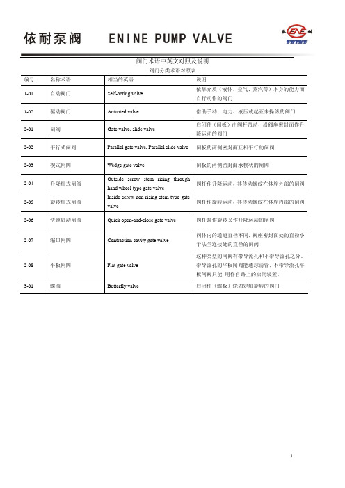
阀门术语中英文对照及说明阀门分类术语对照表编号名称术语相当的英语说明1-01 自动阀门Self-acting valve 依靠介质(液体、空气、蒸汽等)本身的能力而自行动作的阀门1-02 驱动阀门Actuated valve 借助手动、电力、液压或起亚来操纵的阀门2-01 闸阀Gate valve, slide valve 启闭件(闸板)由阀杆带动,沿阀座密封面作升降运动的阀门2-02 平行式闸阀Parallel gate valve, Parallel slide valve闸板的两侧密封面互相平行的闸阀2-03 楔式闸阀Wedge gate valve 闸板的两侧密封面承楔状的闸阀2-04 升降杆式闸阀Outside screw stem rising throughhand wheel type gate valve阀杆作升降运动,其传动螺纹在体腔外部的闸阀2-05 旋转杆式闸阀Inside screw non rising stem type gatevalve阀杆作旋转运动,其传动螺纹在体腔内部的闸阀2-06 快速启动闸阀Quick open-and-close gate valve 阀杆既作旋转又作升降运动的闸阀2-07 缩口闸阀Contraction cavity gate valve 阀体内的通道直径不同,阀座密封面处的直径小于法兰连接处的直径的闸阀2-08 平板闸阀Flat gate valve 这种类型的闸阀有带导流孔和不带导流孔之分。
带导流孔的平板闸阀能通球清管,不带导流孔平板闸阀只能用作官路上的启闭装置。
3-01 蝶阀Butterfly valve 启闭件(蝶板)绕固定轴旋转的阀门编号名称术语相当的英语说明3-02 中线球阀Center line-type butterflyvalve蝶板的回转中心(即阀门轴中心)位于阀体的中心线和蝶板的密封截面上的蝶阀3-03 单偏心蝶阀Single-eccentric centerbutterfly valve蝶板的回转中心(即阀门轴中心)位于阀体的中心线上且蝶板密封截止面形成一个尺寸偏置的蝶阀3-04 双偏心球阀Double-eccentric centerbutterfly valve蝶板的回转中心(即阀门轴中心)与蝶板密封截面形成一个尺寸偏置,并与阀体中心线形成另一个尺寸偏置的蝶阀3-05 三偏心球阀Three-eccentric centerbutterfly valve蝶板回转中心(即阀门轴中心)与蝶板密封面形成一个尺寸偏置,并与阀体中心线形成另一个尺寸偏置;阀体密封面中心线与阀座中心线(即阀体中心线)形成一个角偏置的阀门4-01 旋转阀Rotary valve 启闭件沿阀座密封曲面轴心作相对旋转运动的阀门4-02 球阀Ball valve 启闭件(球体)绕垂直于通路的轴线旋转的阀门4-03 浮动球球阀Float ball valve 球体不带有固定轴的球阀4-04 固定球球阀Fixed ball valve 球体带有固定轴的球阀4-05 弹性球球阀Flexible ball valve 球体上开有弹性槽的球阀4-06 旋塞阀Cock, plug 启闭件(塞子)绕其轴线旋转的阀门4-07 紧定式旋塞阀Clampyte plug valve 塞体内不带填料,塞子与塞体密封面的密封依靠拧紧旋塞下面的螺母来实现的旋塞阀4-08 填斜式旋塞阀Gland packing plug valve 采用填料密封的旋塞阀4-09 自封式旋塞阀Self-sealing plug valve 塞子与塞体间的密封主要依靠介质本身的压力来实现的旋塞阀4-10 油封式旋塞阀Lubricated plug valve 采用油脂密封的旋塞阀4-11 旋柱阀Cock, plug 启闭件(圆柱形塞子)绕其轴线旋转的阀门5-01 挡板阀Baffler valve 启闭件(挡板)在阀座密封上到阀座密封面以外作相对运动,但又不穿过阀座密封面的阀门5-02 截止阀Globe valve, stop valve 启闭件(阀瓣)由阀杆带动,沿阀座(密封面)轴线作升降运动的阀门5-03 上螺纹阀杆截止阀Outside screw stem stop valve 阀杆螺纹在壳体外面的截止阀5-04 下螺纹阀杆截止阀Inside screw stem stop valve 阀杆螺纹在壳体内的截止阀编号名称术语相当的英语说明5-05 直通式截止阀Globe valve 介质的进出口两个通道在同一个方向上,呈180°的截止阀5-06 角式截止阀Angle pattern globe valve 介质的进出口两个通道呈90°的截止阀5-07 三通截止阀Three way stop valve 具有三个通道的截止阀5-08 直流式截止阀Oblique type globe valve 阀杆和通道成一定角度的截止阀5-09 柱塞式截止阀Plunger type globe valve 柱塞式截止阀是常规截止阀的变形,其阀瓣和阀座是按柱塞的原理设计的,吧阀瓣设计成柱塞,阀座设计成套环,靠柱塞和套环的配合实现密封5-10 针形截止阀Needle globe valve 阀座孔的尺寸闭工程通径小的截止阀6-01 节流阀Throttle valve 通过启闭件(阀瓣)改变通路截面积以调节流量、压力的阀门6-02 勾形阀瓣节流阀Trench type disc throttle valve常用于深冷装置中的膨胀阀6-03 窗形阀瓣节流阀Window type disc throttle valve适用于工程通径较大的节流阀6-04 塞形阀瓣节流阀Plug disc throttle valve 适用于中、小口径的节流阀7-01 止回阀Check valve ,Non-return valve 启闭件(阀瓣)靠介质作用力,自动组织介质逆流的阀门7-02 旋启式止回阀Swing check valve 阀瓣绕体墙腔内固定轴旋转运动的止回阀7-03 单板旋启式止回阀Single disc swing check valve只有一个阀瓣的旋启式止回阀7-04 多半旋启式止回阀Multi-disc swing check valve 具有两个以上阀瓣的旋启式止回阀7-05 升降式止回阀Lift check valve 阀瓣垂直于阀座孔轴线作升降运动的止回阀7-06 底阀Foot valve 安装在泵吸入管端,以保证吸入管内被税充满的截止阀7-07 弹簧载荷升降式止回阀Spring-loaded lift check valve 该阀不仅能降低水击压力,而且流道通畅,流阻很小7-08 弹簧载荷环形阀瓣升降式止回阀Spring-loaded annular disc liftcheck valve该阀与通常结构的升降式止回阀相比,阀瓣行程更小,加之弹簧载荷的作用,使其关闭迅速,因此,更利于降低水击压力7-09 多环形流道升降式止回阀Multi-annulus lift check valve该阀具有最小的阀瓣行程,因此其关闭更为迅速7-10 蝶式止回阀Butterfly swing check valve 形状与蝶阀相似,其阀瓣绕固定轴(无摇杆)做旋转运动的止回阀7-11 管道式止回阀Line check valve 阀瓣沿着阀体中心线滑动的止回阀。
电动阀门执行器出口英文使用说明书

Non-Invasive Electric Actuator Electronic control module debugginginstructionsVersion V201SummaryThis component can receive the DCS system on-off signals (passive dry contact of active, active 24 v, 220 v, keep running can switch) or analog signals (DC4-20 ma, 0 to 10 v, etc.), direct drive electric actuators switch action or adjust the action. Output DC4-20 ma feedback current and contact/remote control state instructions. The component integration the servo control unit, solid-state drive unit, liquid crystal display unit, knobs and other ancillary units and aluminum shell assembly operation.The product operates as a fool camera is simple, like intelligent perfect protection function.2Operating Instructions2.1Knob Operating InstructionsThe red knob is the mode button, can be switched between Local/Stop/Remote. Or in a set state, to save the menu contents (from the stop bit screwed to the site) or to exit the menu(from the stop bit screwed into the remote).Black knob for the operating button can be opened or closed operation at the local.Or to plus or minus in the set state.With button operation, short time effect for the inching mode. When the operation button is effective for more than 3 seconds, in the lower right corner of the LCD, the bc is displayed automatically entered into the hold mode. When actuator movement, click the action button reverse rotation or spin mode button to Stop, the actuator Array stops.2.2 setting tool description (setting tool are optional, needto please when ordering special instructions)"Up" button = Open calibration key, "Down" button = close calibrationkey, "Enter" button = Confirm key or Save key"Stop" button = stop key, "Open" button = open key, "Close" button =close key.When mode button at Local location, press "Open" button to performopen, press "Close" button to perform off. In the action, press the"Stop" button to stop the move, short press "Close" to stop the openingprocess, short press "Open" to stop the closing process.In local mode, even by three "Up" key to enter the open position calibration status, "Open", "Close" and "Stop" keys to control the electric actuator to open, close and stop, "Enter" key to save the trip, "Stop "key is used to return.In local mode, even by three "Down" key to enter the closed position calibration status, like the rest of the operation as above.3Signal query (LCD lower left corner for a signal check area) 3.1 Remote control signal inquiryWhen the mode button is screwed into the Remote, the remote control signal received is displayed in the lower-left corner of the LCD. Switch type: show OP represents a open signal, show CL represents a close signal, show BC represents a keep signal (multi state of coexistence of alternate display). Regulating type: to display the received control current value or voltage value.3.2 Valve position signal queryWhen the mode button is screwed onto the Local, the LCD shows the valve position signal in lower left corner. When using a potentiometer, show the percentage of resistance (d01 ~ d99); When using 12 encoder, shows the percentage of the encoder (b01 ~ b99); When using 18 encoder, display micrometer ratio of the encoder (001 to 999).4 4 Stroke calibrations4.1 Calibration for close limit:The mode button at the Stop position, the rotary operation knob to the Close position for about 3 seconds, until the letter L is flashing of the LCD to release operation button, then the mode button to the Local position, now letter L no longer flashes and the system into the closed position calibration status. The actuator can open or close by the operating button. When the actuator operates to the closed position, then the mode button to spin the Stop position, and back to the Local position, at this time the red LED flashing two times said the closed position calibration is completed. If the mode button is screwed to the Remote position from Stop position, that exit travel calibration.4.2 Calibration for open limitThe mode button at the Stop position, the rotary operation knob to the Open position for about 3 seconds, until the letter H is flashing of the LCD to release operation button, then the mode button to the Local position, now letter H no longer flashes and the system into the open position calibration status. The actuator can open or close by the operatingmode button to spin the Stop position, and back to the Local position, at this time the green LED flashing two times said the open limit position calibration is completed. If the mode button is screwed to the Remote position from Stop position, that exit travel calibration.Note: When you save a stroke, display Fu or Fn characters on the LCD, please re-adjust potentiometer or rotary encoder range, and recalibrate the trip.5Feedback current trimming5.1 Feedback current 4mA trimmingThe mode button at the Stop position, the rotary operation knob to the Open position for about 10 seconds, until the letter LF is flashing of the LCD to release operation button, then the mode button to the Local position and back to the Stop position, and the system into the 4mA current trimming status. At this point,the size of the output current can be adjusted by the operating button. When adjusting the output current reaches 4mA, then mode button to spin the Local position, this time the red LED flashes three times, said 4mA output current trim is complete. If the mode button to Stop position from Remote position, which exit status of the output current trim.5.2 Feedback current 20mA trimmingThe mode button at the Stop position, the rotary operation knob to the Open position for about 10 seconds, until the letter HF is flashing of the LCD to release operation button, then the mode button to the Local position and back to the Stop position, and the system into the 20mA current trimming status. At this point,the size of the output current can be adjusted by the operating button. When adjusting the output current reaches 4mA, then mode button to spin the Local position, this time the green LED flashes three times, said 20mA output current trim is complete. If the mode button to Stop position from Remote position, which exit status of the output current trim.6About dead zoneThe dead zone to adapt automatically, without setting can ensure that in any conditions without oscillation, and the positioning precision is higher.7Alarm description (error code displayed on the LCD in the lower right corner) FaultcodeFault informationFA Actuator running direction errorFu V alve position potentiometer or encoder Angle is too largeFn V alve position potentiometer or encoder Angle is too smallFP Power phaseFF Broken valve position potentiometer, rotary to blind or pick the wrong line, or encoder failure.FC Over closed torqueFO Over open torqueFH Remote control signals to open and close signals exist (only on-off type)FS Control current signal is lost (only positioning)Fb Current control signal calibration error(only positioning)Fd Stall or other causes the valve position does not changeFL Limit contact line or torque contact line reversedFE The motor is too hot or the torque public terminal is openNOTE: The green LED is the open limit position light on the screen, the red LED is closed position light on the screen.8Advanced SettingsNOTE: All the Advanced Settings can be set after the mode button in the "Local" position. Advanced settings must open the electrical box cover and you can operate. The Close Key and Open Key mentioned below are in the electronic control board.8.1 Action when the control current loss:(Only positioning type, default: Remain in Situ)8.1.1 To press the “Close Key” and power up for 3 seconds until the red LED on the board is lit. And you release the key, then the red LED flashes three times; the “FullClose” setup is completed.8.1.2 To press the “Open Key” and power up for 3 seconds until the green LED on the board is lit. And you release the key, then the green LED flashes three times; the “Full Open” setup is completed.8.1.3 Simultaneously press two keys and power up for 3 seconds until the green and red LEDs on the board are lit. And you release the two keys simultaneously, then the two LEDs flashes three times; the “Remain in Situ” setup is completed.8.2 Control current calibration:(Only positioning type)8.2.1 To send 4mA control current to the module from the outside, press the “Close Key” and power up for 10 seconds until the red LED on the board is lighted second times. And you release the key, then the red LED flashes three times; and the4mA calibration is completed.8.2.2 To send 20mA control current to the module from the outside, press the “Open Key” and power up for 10 seconds until the green LED on the board is lighted second times. And you release the key, then the green LED flashes three times; and the20mA calibration is completed.8.3 Polarity for the control current:(Only positioning type)20mA = Full Open /4mA = Full Open (default:20mA = Full Open) Simultaneously press “Open Key” and “Close Key” and then power up for 10 seconds. To release the key after the red LED and green LED second lights up. Short press “Open Key” or “Close Key” to alternately lit red LED or green LED. The red LED light represents “20mA = Full Open”, the green LED light represents “4mA = Full Open”. Simultaneously press “Open Key” and “Close Key” for 3 seconds. To release two keys after the two LEDs lights up. Then corresponding LED flashes three times, the polarity for the control current setup is complete.8.4 Two-Wire Control:(Only on-off type)Disable or Open First or Close First (default: Disable)8.4.1Close FirstYou press “Close Key” and then power up for 10 seconds. The key is released after the red LED second light up. And the red LED flashes three times, this setup is complete. This Close First refers to the actuator close operation when voltages signal on the “Remote Close” terminal of the actuator. But no voltage signal, actuators open operation. When wiring, “Remote Open” terminal connected to 24V +.8.4.2Open FirstYou press the “Open Key” and then power up for 10 seconds. The key is released after the green LED second light up. And the green LED flashes three times, this setup is complete.This Open First refers to the actuator open operation when voltages signal on the “Remote Open” terminal of the actuator. But no voltage signal, actuators close operation. When wiring, “Remote Close” terminal connected to 24V +.8.4.3 DisableYou press the two keys simultaneously and then power up for 10 seconds. The key is released after the two LEDs second lights up. Then the two LEDs flashes three times, this setup is complete.8.5 Close direction:Clockwise /Anti-clockwise (default:Clockwise)You press the “Open Key” and “Close Key” simultaneously and then power up for 20 seconds. The keys are released after the red LED and green LED third lights up. Short press “Open Key” or “Close Key” to alternately lit red LED or green LED. Red LED light represents “Clockwise”, green LED light represents “Anti-clockwise”. You press the two keys simultaneously for 3 seconds. The keys is released after the two LEDs light up. Then corresponding LED flashes three times, the Close direction setup is complete.9Common problems to deal withPower LED is not lit or digital display does not show 1. Power is not actually access. 2. voltage is too low 3. Wiring fault. 4. Module badLEDs and digital display abnormal 1. See fault code.2. Query information.3. Replace the moduleAfter power on ,actuator can be not control in the LOCAL and REMOTE mode 1. Wiring fault or loose wiring. 2. Fault Protection.3. Motor bad or stuck.4. Bad start capacitor.5. module badLOCAL mode work is normal but the REMOTE mode can't control 1. No signal or junction anti- , 2. Bad or no knob plate in Remote3. Positive / reaction set wrong.4. Module badREMOTE mode work is normal but the LOCAL mode can't control 1. Not in LOCAL mode. 2. Knobs board bad or not at the scene mode. 3. Operation button is not properly screwed in placeActuator can open but not close or can close but not open 1. Torque wiring fault or loose wiring. 2. to limit position or over torque3. Motor bad or stall or wiring fault.4. Module badThe action immediately after power on 1. Wiring fault. 2. control signal is present3. Implementation the action when the control current loss4. Set the wrong.5. module badThe middle position can move but to the limit position does not move 1. Reverse limit switch line. 2. Motor bad or loose wiring 3. Module badThe direction of movement is the anti 1. Motor lines reversed. 2. Anti valve calibration.3. Signal Reverse4. Polarity for the control current or closing direction set wrong.No output current or sometimes no 1. The output wiring fault or bad. 2. Module bad 3. potentiometer wiring fault or loose wiringFeedback current is larger or smaller or unchanged 1.Potentiometer failure. 2. Calibration error.3. module bad4. potentiometer meshing with drive gear not wellNote: Please strictly in accordance with the wiring diagram electrical wiring connection.Like has the change, without notice。
(完整版)道闸产品说明书

请您在使用产品前仔细阅读本手册尊敬的用户:首先感谢您选择了由本公司为您精心制造的道闸!能为您提供服务深感荣幸!为确保本产品的安全使用,充分发挥本产品的优良性能,提高产品的使用寿命,请通读本手册,了解相关的产品信息。
通过阅读本手册,你能更详细的了解到本产品的性能特点及相关技术参数,并通过相关示意图明确产品结构。
本手册讲述了安装过程中可能遇到的问题,并作了相关分析,提供了相应的解决方案,方便用户对产品安装调试及进行保养维护。
本资料中部分图片是示意图,仅供参考,若图片与实物不符,请以以实物为准。
本公司全权负责该资料的修订及解释,并保留更改产品及技术参数不另行通知的权利,敬请谅解。
产品性能特点我公司精心设计并制作的一款新型道闸,使用方便,安全可靠,简洁大方、美观亮丽。
广泛用于机关单位、小区、停车场、厂区大门等出入通道口。
一.机芯特性●采用最稳定的非等速运行机构,使闸杆慢起动、快运行,慢停止,排除闸杆在运行开、关中带来的抖动。
延长产品使用寿命。
●道闸左右可换向,根据现场需要可随意更换闸杆的起落方向,适用范围更加广泛。
●采用高负苛承重带座轴承,使机芯部分更加稳固。
●机械限位可调,使安装调试更加方便快捷。
●采用高灵敏限位开关,瞬间控制起杆、落杆到位准确。
●一体化涡轮蜗杆传动减速异步电机,传动平稳,噪音低,结构紧凑,能实现自锁。
●电机设智能过热保护系统,在频繁的使用下,控制了电机的温升,使电机不易烧坏。
●手动开闸机构,停电时可通过电机手轮自动起落闸杆,不受限制。
二.控制系统●采用数字芯片技术,防砸、地感、IC接口集为一体,稳定性好,误动概率为零,特别设有延时保护功能,具有双重控制功效。
●采用升降超时与电机过热保护,防止闸机非正常损坏。
●采用原装进口的大功率继电器,确保道闸可靠运行。
●采用原装进口的光电隔离保护电路,确保信号完整和抗强干扰。
●集成高性能百万组学习码的无线遥控接收模块,确保操作的稳定性。
●采用独有的灭弧处理电路,确保控制板的使用寿命。
电动门说明书

REV 13ETable of ContentsGeneral Safety (2)Preparation for Installation (3)Parts List (4)Optional Accessories Part List (5)Technical Specifications & Feature (5)Installation Overview (6)Installation of the Opener (6)Manual Operation (7)Installation of chain and chain brackets (7)Installation of Magnets for Limit Switches (9)Connecting Of Power Supply (10)Connecting of the Control Board (10)Setting of the Control Board (11)Test the reversing sensitivity (13)How to learn or erase the remote (13)How to use the remote to control the opener (13)Trouble Shooting (14)Maintenance (14)Thank you for purchasing our sliding gate opener. We are sure that the products will be greatly satisfying as soon as you start to use it.The product is supplied with a user’s manual which encloses installation and safety precautions. These should be read carefully before installation and operation as they provide important information about safety, installation, operation and maintenance. This product complies with the recognized technical standards and safety regulations.General SafetyWARNING! An incorrect installation or improper use of the product can cause damage to persons, animals or properties.• Scrap packing materials (plastic, cardboard, polystyrene etc.) according to the provisions set out by current standards. Keep nylon or polystyrene bags out of children’s reach.•This product was exclusively designed and manufactured for the use specified in the present documentation. Any other use not specified in this documentation could damage the product and be dangerous.• The factory declines all responsibility for any consequences resulting from improper use of the product, or use which is different from that expected and specified in the present documentation.• Do not install the product in explosive atmosphere.•The factory declines all responsibility for any consequences resulting from failure to observe Good Technical Practice when constructing closing structures (door, gates etc.), as well as from any deformation which might occur during use.• Disconnect the electrical power supply before carrying out any work on the installation. Also disconnect any buffer batteries, if fitted.• Fit an omnipolar or magnetothermal switch on the mains power supply, having a contact opening distance equal to or greater than 3,5 mm.• Make sure a residual current circuit breaker with a 30mA threshold is fitted before the power supply mains.• Check that earthing is carried out correctly: connect all metal parts for closure (doors, gates etc.) and all system components provided with an earth terminal.• Fit all the safety devices (photocells, electric edges etc.) which are needed to protect the area from any danger caused by squashing, conveying and shearing.• The factory declines all responsibility with respect to the automation safety and correct operation when other supplier’s components are used.• Only use original parts for any maintenance or repair operation.• Do not modify the automation components, unless explicitly authorized by the factory.• Instruct the product user about the control systems provided and the manual opening operation in case of emergency.• Do not allow persons or children to remain in the automation operation area.•Keep radio control or other control devices out of children’s reach, in order to avoid unintentional automation activation.• The user must avoid any attempt to carry out work or repair on the automation system, and always request the assistance of qualified personnel.• Anything which is not expressly provided for in the present instructions is not allowed.•Before installing the gate opener, check that all moving part as well as the sliding gate is in good mechanical condition, correctly balanced and opens and closes properly.•Save these instructions for future use.Preparation for InstallationBefore proceeding to your opener installation, check if your gate structure is in accordance with the current standards, especially as follows:The gate sliding track is linear and horizontal.The wheels are suitable for use. The gate should be mounted and moved freely. Check that the structure is sufficiently strong and rigid, and that its dimensions and weights conform to those listed in the specifications table of this document. Make sure that the gate is plumb and level. The fence posts must be mounted in concrete. The gate does not bind or drag on the ground.• The gate manual operation can be carried out smoothly along its entire run, and there is no excessive side slipping.• The opening and closing gate stops are positioned.WARNING: Remember that control devices are intended to facilitate gate operation, but can not solve problems due to any defects or deficiency resulting from failure to carry out correct installation or maintenance. Take the product out of its packing and inspect it for damage. Should it be damaged, contact your dealer. Remember to dispose of its components (cardboard, polystyrene, nylon, etc.) according to the current prescriptions.Refer to the following Figures for gate installation.In sake of safety, a positive stop must be mounted on the two end of ground track.Parts ListOptional Accessories Parts ListTechnical Specifications & FeaturesSpecificationsSCG 17 / AC 1500SCG 20 / AC 2400Power supply:120V/60Hz or 230V/50HzMotor voltage:120VAC or 230VACFrequency433.92MHzAbsorbed power:300W500WGate moving speed:15 cm/secondMax gate weight:600KGS/1500LBS1000KGS/2400LBSMax torque:12Nm24NmEnvironmental conditions:From -15°C to +40°CProtection class:IP44Dimensions:25.2×22×25 CMFeatures:·Midway mode.·Quick selection for the gate open/close direction·Reliable rolling code technology for remote control·Emergency release key in case of power failure·Stop/Reverse in case of obstruction during gate opening/closing·Built in adjustable auto-close·Built in motor running limitation: max. 90 sec ·Reliable electromagnetism limit for easy adjustment ·Can be equipped with a wide range accessories Installation OverviewInstallation of the Opener Caution:*Be sure that the opener is installed in a level and paralleled position and is properly secured. Improper installation could result in property damage, severe injury, and/or death.* Before starting installation, ensure that there is no point of friction during the entire movement of the gate and there is no danger of derailment. * Ensure that the safety side panels are present.Necessary Tools: The following tools may be necessary to install the Gate opener. You will need screwdrivers, an electric drill, wire cutters and a wire stripper, a socket set, and possibly access to a welder.When install the opener, you should build a concretepad to support the base plate of opener in order to maintain proper stability.The installation proceeds are as follows:1.Dig a hole for a concrete pad which should be approximately 60 x 32 x 35cm (24〞x13〞x14〞). It may protrude 10 cm (4”) above ground and 25 cm (10”) in depth underground. Increase the pad heightif necessary to protect the system from flooding, heavy snow etc.2.Prepare one or more conduits for the electrical cables before pour concrete. Remember that cable conduits have to pass through the hole in the base plate.3. Pour concrete and before it starts to harden, check that it is parallel to the gate leaf and perfectly level.4. The four anchor bolts must be set into the concrete when it is poured, make sure the position of anchor bolts was placed according to the position of mounting holes on the base plate before concrete become harden.5. Mount the base plate to the concrete Pad. It's only temporary installation. Further adjustment will be required when install the chain.6. Mount the chain box to the base plate by using screws and washers, don’t make the four screws too tight.Manual OperationThe opener should be put in the manual (emergency release) position before fitting the rack, installing the opener and limit switch.The process is as follows:1) Take off the rubber stopple.2) Insert the Release Key(provided)and turn it in counter-clockwise 180° to disengage the clutch between the gear shaft and power output. Now the opener is in the manual operation.Installation of chain and chain brackets1. Chain Brackets1). Please refer to below chain brackets figure,which shows “U” bolt, “L” bracket and chain bolt.Use the “U” bolts (square or round) to attach thechain brackets to gate frame.2). If Both the square bolts and round bolts are notfit for the gate frame, use the appropriate bolts toattach the chain brackets to gate frame.2. How to install the chain1). Place the chain around the top of the idlerwheels and under the drive sprocket in chain box.2). Connect a chain bolt to one end of chain fromchain box by using master link. Then insert the chain bolt to the L bracket and fix them each other bywashers and nuts temporarily. (Nuts will be further adjusted for a proper chain tension later)3). Connect second chain bolt with another end of chain from chain box, then attach bolt to the L bracket on opposite end of gate using the washers and nuts.4). Make sure that the chain is line up exactly with the position where the chain on the chain idler wheel.5). Get the desired chain tension by adjusting two chain bolts of the both end.Cut the unwanted length of chain if necessary.6). Fix the base plate by tightening the washers and nuts.7). Insert the opener shaft into the drive sprocket of chain box.Mount the opener by tightening the bolts and washers.8). Fix the chain box by tightening the four lax screws.* Thoroughly fasten the four nuts as well as spring washers onto anchor bolts tightly, enabling the opener is firmly secured on the concrete pad during the whole gate travel.3. Check position of opener and chain brackets1). The chain brackets must be mounted to the same height as the chain on the idler wheels.2). The opener must be parallel to the gate.3). Make sure there is 1” distance at least between the chain box and the gate after you position the base plate.Installation of Magnets for Limit SwitchesBefore install limit switch, make sure thegate opener is put in manual operation. (theclutch connected with gear shaft isdisengaged) and the mains power supply isdisconnected.Position the two Magnet Componentsapproximately on the gate and move thegate by hand to fix them in place.Fit magnets bracketPush the gate fully closed by hand. Locateand install the magnet bracket so that theopener will stop at the desired close positionwhen the close limit switch approaches it.Push the gate fully open by hand. Locateand install the magnet bracket so that theopener will stop at the desired open positionwhen the open limit switch approaches it.The magnet component with N pole outside must be installed at left side and the magnet component with S pole outside must be installed at right side from the view inside of property.Finally adjust the magnet to the proper position by moving the gate with the motor. The magnet should be less than 1“away from the magnetic limit switch. If it is too far away, the switch will fail to work. The distance between the magnet and the opener should be 0.39”- 0.59” with the opener cover on. Adjust the position of the magnet until the positions of the opening and closing meet the requirement.Connecting Of Power SupplyThe power supply cord should be at least 3×0.75mm2. Connect the live wire and neutral wire to the “L”(2) and “N”(1) terminal respectively; and connect the earth wire to“PE”.Connecting Of the Control Board1. MotorThe BLACK wire of the motor should be connected into the “3” terminal.The YELLOW wire of the motor should be connected into the “4” terminal.The RED wire of the motor should be connected into the “5” terminal.2. Limit SwitchesThe YELLOW wire of the limit switches should be connected into the “8” terminal.The BLACK wire of the limit switches should be connected into the “9” terminal.The RED wire of the limit switches should be connected into the “10” terminal.3. Alarm Lamp (Optional)One wire of the alarm lamp should be connected into the “6” terminal, another should be connected into the “7” terminal.4. Start CapacitorThe two wires of the start capacitor should be connected into the “4”terminal and “5” terminal.5. Photocell(Optional)Use a 2-core cable to connect the “+ ~” terminal of the photocell’s emitter to the “13” terminal, the “- ~”terminal to the “11”terminal. Also the “+ ~”and “- ~”terminals of the photocell’s receiver should be connected to the “13” and “11” terminals in parallel.Use another 2-core cable to connect the “COM”terminal of the receiver to the “13”terminal, the “NC”terminal to the “12” terminal.5. Wired Keypad (24VDC)The RED wire of the wired keypad should be connected into the “13” terminal.The BLACK wire of the wired keypad should be connected into the “11” terminal.The WHITE wire of the wired keypad should be connected into the “13” terminal.The BLUE wire of the wired keypad should be connected into the “14” terminal.6. Push Button (Optional)The push button should be wired to the “13” and “14”terminals. The gate operator works alternately by pushing the button (open-stop-close-stop-open).Setting Of the Control BoardWARNING: Keep away from the gate during you set the gate opener system in case of the unexpected gate moving. Carefully adjust the DIP switches to avoid the risk of machine damage and injury or death. Always ask the help of professional technician /electrician if you have any question.1.DIP SwitchesThe DIP switches are used to set the running time of the motor in pedestrian mode, enable/disable auto close function of the gate operator and fast change the open/close direction which is determined by the position of the gate operator installed.DIP Switch #1–#2: Running time of the motor in Midway ModeDIP Switch #1: ON –2 Seconds OFF –0DIP Switch #2: ON –4 Seconds OFF –0NOTE: The midway mode function would be disabled if both DIP switches are turned off.Factory default setting is disabled.DIP Switch #3: Auto close function enabled/disabledDIP Switch #3: ON –auto close function enabledOFF –auto close function disabledDIP Switch #4: Left/Right open2. PotentiometersPotentiometer A and B are used to adjust the stall force and auto close time of the gate operator separately. Turn potentiometer A clockwise to increase the stall force, and turn it counter-clockwise to decrease the stall force.Turn potentiometer B clockwise to increase the auto close time, and turn it counter-clockwise to decrease the auto close time, the auto close time could be adjusted steplessly from 1 to 99 seconds.E.g.Running time of the operator in pedestrian mode is 2seconds.E.g. Auto close function of the opener has been enabled. Factory default setting is disabled.Test the reversing sensitivityFor the sake of safety,it is very important to test the reversing sensitivity as soon as the control board set is finished.The reversing sensitivity adjustment is inverse correlation with stall force adjustment in potentiometer A and B.In other word, the stall force level is higher; the reversing sensitivity level is lower.Put an immobile object along the gate path, and then operate the gate to strike it during the open and close cycles. The gate must reverse as soon as object is struck with it. If the gate doesn’t reverse, please increase the reversing sensitivity by turning the potentiometer A in counter-clockwise direction. (Turning the stall force potentiometer toward to MIN position to increase the reversing sensitivity)Note 1: If the sensitivity setting is too higher, the gate will stop or reverses very easy by itself while there is little obstruction or resistance such as strong wind or heavy snow sometimes.Note 2: Always check the gate reversing function every each time of control board set or restart after power off.How to learn or erase the remoteLearn the remotePress and release the learn button, the LEARN LEDlight will be on,then press the key in the remote twicein 2 seconds, the LEARN LED light will flash for 4seconds. Now the remote has been learnt successfully.This control board can learn up to six remotes, if youwant to learn more, we recommend that you buy the external receiver(LM138).Erase all the remote codesPress and hold the learn button until the LEARN light is off. Now all remote codes have been erased.How to use the remote to control the operatorKey A is used to operate the operator to work alternately (open-stop-close-stop-open).When the Pedestrian Mode function is enabled, Key B is used to achieve thePedestrian Mode function (open the gate for the pre-setting time). When thePedestrian Mode function is disabled, the operator works alternately (open-stop-close-stop-open) by pressing Key B.TroubleshootingHave a multimeter to check voltage and continuity. Use caution when checking high voltage terminals.MaintenanceEvery six months check the following items for proper operation of the unit.*Lubricate shafts and sprockets.*Keep operator clean at all times.*Check and tighten anchors bolts.* Check for loose or corroded wire* Ensure the operator is well earthed, and correctly terminated.*Always check the Stop/Reverse in case of obstruction function when performing any maintenance.If this function can’t be made operable,remove this operator from service until the cause of the malfunction is identified and corrected.Symptom Possible Solution(s)The remote controldoes not emit any singleCheck the batteries are exhausted, replace them if necessary.The operator doesn’t run.1. Make sure that the power cord is properly plugged into the mains outlet.2. Check the fuse is blown in the control board; if necessary, identify thereason for the failure and then replace a new one.3. Make sure the photocell beam is not blocked if the photocell is used.Check the terminal 11 should be shorted with terminal 12 by a jumper wire.Please reset this jumper wire if it is loss.The gate starts but it is immediately stop or reverse 1. The selected force is too small to move the gate. Turn the Potentiometer clock-wise to increase the force.2. Disconnect the gate from the gate operator and check that the gate slides freely without any binding. 7106 S 220th St, Kent WA 98032 USA *****************************©2012-2014ALEKO All Rights Reserved。
DS-K3Y220(L)X系列闸门屏障快速入门指南说明书
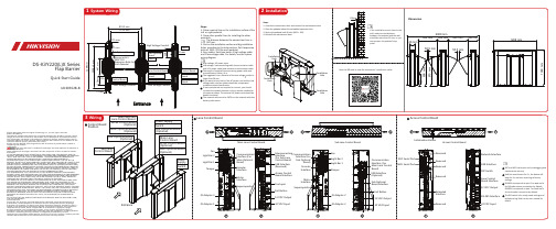
DS-K3Y220(L)X SeriesFlap BarrierQuick Start GuideUD30352B-B©2022Hangzhou Hikvision Digital Technology Co.,Ltd.All rights reserved.About this ManualThe Manual includes instructions for using and managing the Product.Pictures,charts, images and all other information hereinafter are for description and explanation only. The information contained in the Manual is subject to change,without notice,due to firmware updates or other reasons.Please find the latest version of this Manual at the Hikvision website(https:///).Please use this Manual with the guidance and assistance of professionals trained in supporting the Product.Trademarksand other Hikvision’s trademarks and logos are the properties of Hikvision in various jurisdictions.Other trademarks and logos mentioned are the properties of their respective owners. DisclaimerTO THE MAXIMUM EXTENT PERMITTED BY APPLICABLE LAW,THIS MANUAL AND THE PRODUCT DESCRIBED,WITH ITS HARDWARE,SOFTWARE AND FIRMWARE,ARE PROVIDED “AS IS”AND“WITH ALL FAULTS AND ERRORS”.HIKVISION MAKES NO WARRANTIES, EXPRESS OR IMPLIED,INCLUDING WITHOUT LIMITATION,MERCHANTABILITY, SATISFACTORY QUALITY,OR FITNESS FOR A PARTICULAR PURPOSE.THE USE OF THE PRODUCT BY YOU IS AT YOUR OWN RISK.IN NO EVENT WILL HIKVISION BE LIABLE TO YOU FOR ANY SPECIAL,CONSEQUENTIAL,INCIDENTAL,OR INDIRECT DAMAGES,INCLUDING, AMONG OTHERS,DAMAGES FOR LOSS OF BUSINESS PROFITS,BUSINESS INTERRUPTION, OR LOSS OF DATA,CORRUPTION OF SYSTEMS,OR LOSS OF DOCUMENTATION,WHETHER BASED ON BREACH OF CONTRACT,TORT(INCLUDING NEGLIGENCE),PRODUCT LIABILITY, OR OTHERWISE,IN CONNECTION WITH THE USE OF THE PRODUCT,EVEN IF HIKVISION HAS BEEN ADVISED OF THE POSSIBILITY OF SUCH DAMAGES OR LOSS.YOU ACKNOWLEDGE THAT THE NATURE OF THE INTERNET PROVIDES FOR INHERENT SECURITY RISKS,AND HIKVISION SHALL NOT TAKE ANY RESPONSIBILITIES FOR ABNORMAL OPERATION,PRIVACY LEAKAGE OR OTHER DAMAGES RESULTING FROM CYBER-ATTACK, HACKER ATTACK,VIRUS INFECTION,OR OTHER INTERNET SECURITY RISKS;HOWEVER, HIKVISION WILL PROVIDE TIMELY TECHNICAL SUPPORT IF REQUIRED.YOU AGREE TO USE THIS PRODUCT IN COMPLIANCE WITH ALL APPLICABLE LAWS,AND YOU ARE SOLELY RESPONSIBLE FOR ENSURING THAT YOUR USE CONFORMS TO THE APPLICABLE LAW.ESPECIALLY,YOU ARE RESPONSIBLE,FOR USING THIS PRODUCT IN A MANNER THAT DOES NOT INFRINGE ON THE RIGHTS OF THIRD PARTIES,INCLUDING WITHOUT LIMITATION,RIGHTS OF PUBLICITY,INTELLECTUAL PROPERTY RIGHTS,OR DATA PROTECTION AND OTHER PRIVACY RIGHTS.YOU SHALL NOT USE THIS PRODUCT FOR ANY PROHIBITED END-USES,INCLUDING THE DEVELOPMENT OR PRODUCTION OF WEAPONS OF MASS DESTRUCTION,THE DEVELOPMENT OR PRODUCTION OF CHEMICAL OR BIOLOGICAL WEAPONS,ANY ACTIVITIES IN THE CONTEXT RELATED TO ANY NUCLEAR EXPLOSIVE OR UNSAFE NUCLEAR FUEL-CYCLE,OR IN SUPPORT OF HUMAN RIGHTS ABUSES.IN THE EVENT OF ANY CONFLICTS BETWEEN THIS MANUAL AND THE APPLICABLE LAW, THE LATTER PREVAILS.Data ProtectionDuring the use of device,personal data will be collected,stored and processed.To protect data,the development of Hikvision devices incorporates privacy by design principles.For example,for device with facial recognition features,biometrics data is stored in your device with encryption method;for fingerprint device,only fingerprint template will be saved,which is impossible to reconstruct a fingerprint image.As data controller,you are advised to collect,store,process and transfer data in accordance with the applicable data protection laws and regulations,including without limitation,conducting security controls to safeguard personal data,such as, implementing reasonable administrative and physical security controls,conduct periodic reviews and assessments of the effectiveness of your security controls.If thewall,3.SlotholesboltswiringHighLowandSOCmaintenanceRegulatory InformationFCC InformationPlease take attention that changes or modification not expressly approved by the party responsible for compliance could void the user’s authority to operate the equipment.FCC compliance:This equipment has been tested and found to comply with the limits for a Class B digital device,pursuant to part 15of the FCC Rules.These limits are designed to provide reasonable protection against harmful interference in a residential installation.This equipment generates,uses and can radiate radio frequency energy and,if notinstalled and used in accordance with the instructions,may cause harmful interference to radio communications.However,there is no guarantee that interference will not occur in a particular installation.If this equipment does cause harmful interference to radio or television reception,which can be determined by turning the equipment off and on,the user is encouraged to try to correct the interference by one or more of the following measures:—Reorient or relocate the receiving antenna.—Increase the separation between the equipment and receiver.—Connect the equipment into an outlet on a circuit different from that to which the receiver is connected.—Consult the dealer or an experienced radio/TV technician for help.This equipment should be installed and operated with a minimum distance 20cm between the radiator and your body.FCC ConditionsThis device complies with part 15of the FCC Rules.Operation is subject to the following two conditions:1.This device may not cause harmful interference.2.This device must accept any interference received,including interference that may cause undesired operation.This product and -if applicable -the supplied accessories too are marked with "CE"and comply therefore with the applicable harmonized European standards listed under the RE Directive 2014/53/EU,the EMC Directive 2014/30/EU,the RoHS Directive 2011/65/EU.2006/66/EC (battery directive):This product contains a battery that cannot be disposed of as unsorted municipal waste in the European Union.See the product documentation for specificbattery information.The battery is marked with this symbol,which may include lettering to indicate cadmium (Cd),lead (Pb),or mercury (Hg).For proper recycling,return the battery to your supplier or to a designated collection point.For more information see:2012/19/EU (WEEE directive):Products marked with this symbol cannot be disposed of as unsorted municipal waste in theEuropean Union.For proper recycling,return this product to your local supplier upon the purchase of equivalent new equipment,or dispose of it at designated collection points.For more information see:Press Hold leval Press menuPress Press Press paramter •The to prepare •If the the Power RS-485B connection fingerprint Scan the QR code to view the user manual.。
阀门的安装说明书(中英文)

阀门的安装说明书(中英文对照)焊接与银钎焊SOLDERING AND SILVER BRAZING务必记住所推荐的阀门的用途是什么,并对所应用的环境进行分析,这样才能决定选用最适合安装什么样的阀门。
在安装正确的阀门之前,为了防止损坏阀门,并保证充分发挥阀门的工作性能,请阅读一下安装指南:Analyze the application to determine which valve is best suited for installations, keeping in mind the service for which the valve is recommended. Before installing the correct valve, review the installation instructions to prevent damage to the valve and to assure its maximum efficiency:先沿着垂直方向切割管道,并修整、去除毛刺,测量管径。
Cut tube end square. Ream, burr and size.使用纱布或钢丝刷清除管道和切割部位,使其金属表面发光发亮。
建议不要使用钢丝绒。
Use sand cloth or steel wire brush to clean both ends to a bright metal finish. Steel wool is not recommended.在管道的外面和焊接罩的内部涂上焊剂,焊剂必须完全覆盖焊接表面。
请有节制地使用焊剂。
Apply flux to outside of tube and inside of solder cup. Surfaces to be joined must be completely covered. Use flux sparingly.要确保阀门处于开启状态。
闸机说明书

Spring release latch check switch (LCS)for Magnum low voltage circuit breakersBE PERMITTED TO WORK ON THE EQUIPMENT (2) ALWAYS DE-ENERGIZE PRIMARY AND SECONDARY CIRCUITS IF A CIRCUIT BREAKER CANNOT BE REMOVED TO A SAFE WORK LOCATION (3) DRAWOUT CIRCUIT BREAKERS SHOULD BE LEVERED (RACKED) OUT TO THE DISCONNECT POSITION. (4) ALL CIRCUIT BREAKERS SHOULD BE SWITCHED TO THE OFF POSITION AND MECHANISM SPRINGS DISCHARGED.FAILURE TO FOLLOW THESE STEPS FOR ALLPROCEDURES DESCRIBED IN THIS INSTRUCTIONLEAFLET COULD RESULT IN DEATH, BODILY INJURY, OR PROPERTY DAMAGE.PRODUCT LABELS MUST BE FOLLOWED. OBSERVE THE FIVE SAFETY RULES. • DISCONNECTING;• ENSURE THAT DEVICES CANNOT BE ACCIDENTALLY RESTARTED;• VERIFY ISOLATION FROM THE SUPPLY;• EARTHING AND SHORT-CIRCUITING; AND;• COVERING OR PROVIDING BARRIERS TO ADJACENT LIVE PARTS.Section 1: General informationA latch check switch (LCS) indicates when the circuit breaker is “ready to close” (Figure 1). The Internal version of the LCS is wired to the spring release. It will not permit activation of the spring release until the circuit breaker is fully charged and the trip latch is reset.This product is intended for use in Magnum circuit breakers with PXR or Digitrip trip units.Required tools• 1/4-inch drive ratchet •10 mm socketKit parts identificationRefer to Figure 1 for visual identification of the contents of kit:Figure 1. Contents of kit.ote: N All images show a Magnum circuit breaker with a PXR trip unit unless stated otherwise. Some compo-nents, such as the trip unit, not shown for clarity.LCS (internal version shown)2Instructional Leaflet IL2C12769Effective December 2021Spring release latch check switch (LCS) for Magnum low voltage circuit breakersEATON Section 2: Installation of internal remote LCSTo install the LCS, proceed with the following steps:Step 1: Remove the front cover by unscrewing the hex-head captive bolts (four for three-pole, six for four-pole) that join the cover to the breaker housing using a 10 mm 1/4-inch drive socket. Then hold the charge handle down at about a 45-degree angle to pull off the cover. Step 2: Place the appropriate label on the front cover nameplate space located under “Accessories”.Figure 2. Steps 1 and 2.Step 3: Remove the accessory (if installed) and the spring release (SR) from the indicated positions on the accessory tray by lifting its lock up and sliding the accessory toward the front of the breaker. Then lift accessory up and out of tray. Do not disconnect the wiring.Figure 3. Step 3.Step 4: Plug the connector from the LCS onto the two pins of the spring release circuit board. Then push the LCS into the slot in theaccessory tray. Make sure the LCS is fully seated.Figure 4. Step 4.Step 5: Reinstall any accessory that was removed in Step 3.Step 6: Test the installation.CLOSED. FAILURE TO FOLLOW THIS ACTION COULD RESULT IN A SERIOUS INJURY.With the breaker OPEN and DISCHARGED, push down on the trip lever platform (to its stop) and release. The LCS should not operate. This is indicated by the absence of an audible “click” from the switch.Now charge the breaker using the manual handle. When the breaker is fully charged, the trip lever will return to the latched (platform level) position. Repeat the above test by pushing the trip lever platform down and releasing it. An audible “click” from the switch should be heard.Figure 5. Step 6.Step 7: Reinstall the front cover. Push the CLOSE and then the OPEN pushbuttons to discharge all energy from the mechanism, leaving it in an OPEN and DISCHARGED status.3Instructional Leaflet IL2C12769Effective December 2021Spring release latch check switch (LCS) for Magnum low voltage circuit breakers EATON Notes:Eaton1000 Eaton Boulevard Cleveland, OH 44122 United States © 2021 EatonAll Rights ReservedPrinted in USAPublication No. IL2C12769H08/ TBG 001546 December 2021Eaton is a registered trademark.All other trademarks are propertyof their respective owners.Spring release latch check switch (LCS) for Magnum low voltage circuit breakersInstructional Leaflet IL2C12769 Effective December 2021Disclaimer of warranties andlimitation of liabilityThe information, recommendations, descriptions, and safety notations in this document are based on Eaton Corporation’s (“Eaton”) experience and judgment, and may not cover all contingencies. If further information is required, an Eaton sales office should be consulted.Sale of the product shown in this literature is subject to the terms and conditions outlined in appropriate Eaton selling policies or other contractual agreement between Eaton and the purchaser.THERE ARE NO UNDERSTANDINGS, AGREEMENTS, WARRANTIES, EXPRESSED OR IMPLIED, INCLUDING WARRANTIES OF FITNESS FOR A PARTICULAR PURPOSE OR MERCHANTABILITY, OTHER THAN THOSE SPECIFICALL Y SETOUT IN ANY EXISTING CONTRACT BETWEEN THE PARTIES. ANY SUCH CONTRACT STATES THE ENTIRE OBLIGATION OF EATON. THE CONTENTS OF THIS DOCUMENT SHALL NOT BECOME PART OF OR MODIFY ANY CONTRACT BETWEEN THE PARTIES. In no event will Eaton be responsible to the purchaser or user in contract, in tort (including negligence), strict liability, or otherwise for any special, indirect, incidental, or consequential damage or loss whatsoever, including but not limited to damage or loss of use of equipment, plant or power system, cost of capital, loss of power, additional expenses in the use of existing power facilities, or claims against the purchaser or user by its customers resulting from the use of the information, recommendations, and descriptions contained herein.The information contained in this manual is subject to change without notice.。
SSPB中文使用说明书

目录第1章概述 (1)第2章主要特点 (2)第3章技术参数 (4)3.1 使用环境条件 (4)3.2 仪器输入特性 (4)3.3 时基 (7)3.4 测量指标 (8)3.5 测量运算(频率测量)…………………………………163.6 其它特性…………………………………………………16第4章面板介绍 (19)4.1 前面板……………………………………………………194.2 前面板指示灯……………………………………………204.3 前面板菜单…………………………………………………224.4 显示屏……………………………………………………294.5 显示特殊字符……………………………………………304.6 后面板……………………………………………………31第5章使用说明 (33)5.1 测量前的工作……………………………………………335.2 使用测量控制键………………………………………345.3 使用输入/选择(箭头)键………………………………365.4 使用测量功能菜单键…………………………………385.5 使用闸门和外触发菜单键 (47)5.6 使用极限功能菜单键 (49)5.7 使用运算功能菜单键 (50)5.8 使用通道1和通道2触发方式菜单键和输入参数设置键 (55)5.9 使用存储、调用和打印菜单键 (56)5.10 使用系统设置菜单键…………………………………585.11 前面板出错显示信息 (61)5.12 *RST状态和RECALL 0状态……………………………62第6章软面板使用说明 (64)6.1 软面板应用程序安装…………………………………646.2 软面板应用程序卸载…………………………………686.3 软面板应用程序启动…………………………………696.4 软面板应用程序说明…………………………………71第7章编程说明 (73)7.1 程控接口概述……………………………………………737.2 程控接口硬件连接………………………………………737.3 程控命令简述……………………………………………757.4 程控命令语法……………………………………………837.5 程控命令详解……………………………………………87第8章注意事项与检修 (103)8.1 出错处理…………………………………………………1038.2 检修注意事项……………………………………………1038.3 常见问题解答……………………………………………104第9章仪器设备及附件 (105)9.1 仪器配件…………………………………………………1059.2 仪器选配件 (105)第1章概述SP3386&SP312B系列等精度通用计数器是我公司新研制的两种高精度的测频测时仪器。
- 1、下载文档前请自行甄别文档内容的完整性,平台不提供额外的编辑、内容补充、找答案等附加服务。
- 2、"仅部分预览"的文档,不可在线预览部分如存在完整性等问题,可反馈申请退款(可完整预览的文档不适用该条件!)。
- 3、如文档侵犯您的权益,请联系客服反馈,我们会尽快为您处理(人工客服工作时间:9:00-18:30)。
一、Introduction
Mainly for urban water supply and drainage, chemical engineering, flood control, irrigation and other materials into the hydraulic sector, the outlet for flow channel switching, or the flow purposes. It can be widely used with the water plant, sewage water treatment plants, urban storm sewage pumping station, water conservancy and flood control and other industries. Gate based on useless can be divided into: 1, the channel gate. Used to channel the middle, do throttle use, usually sealed on three sides. 2, water gate. Imports and exports for the waterways, making open or closed, generally surrounded by seals. 3, regulating gates. For regulating the flow size. 4, weir gate. For regulating the water level. My company produced the characteristics of the gate:
1Light weight
2 Torque Small: Due to gate light, a small frictional resistance between the gate and the slide.
3 long life: As between the gate and the slide can only last a short contact with the sealing surface wear is very Small.
4 easy maintenance: wedge-shaped blocks can be adjusted, if after years of use, such as a partial leakage, simply
5 wedge adjustment to increase the amount of sealing rubber ring can be compressed, saving time and effort.
1
6.operating bodies: can use different conditions. Manually. Air. Electric.
二、Technical Parameters: Nominal size: 300 * 300 ~ 2600 * 2600; working head:
≤ 10m-H2O; Operating Temperature: -10 ~ 80 ℃.
三、Material
3.1 Material
NO. Parts Material
1 Door Cast iron
1
2 door frame Cast iron
3 Operating rod Stainless steel
4 the connection sleeve
and stent
Cast iron
5 Console Cast iron
6 hoist standard parts
● channel gate (on three sides sealing water)
● water gates (four sides sealed water)
● Large gate (four sides sealed water)
規格
DN×DN
W H L1
300×300 516 720 75
350×350 566 820 75
400×400 616 920 75
500×500 716 1120 75
600×600 816 1400 87
700×700 916 1600 87
800×800 1016 1800 87
900×900 1116 2000 87
1000×1000 1216 2200 87
1100×1100 1316 2400 87
1200×1200 1416 2600 87
1300×1300 1516 2800 100
1400×1400 1650 3000 100
1500×1500 1750 3200 100
1。