球阀使用说明书英文版(ball valve)
手动球阀使用说明

球阀使用说明书 Q41F 浮动式球阀球 阀 (Ball Valve)球阀是由旋塞演变而来的,它的启闭件为一个球体,利用球体绕阀杆的轴线旋转90度实现开启和关闭的目的。
球阀在管道上主要用于切断、分配和改变介质流动方向,设计成V 形开口的球阀还具有良好的流量调节功能。
球阀不仅结构简单,密封性好,而且在一定的公称通径范围内体积较、重量轻、材料耗阀门品种之一。
特别是在美、日、德、法、意、西、英等工业发达国家,球阀的使用非常广泛,使用品种和数量仍在继续扩大,并向高温、高压、大口径、高密封性、长寿命、优良的调节性能以及一阀多功能方向发展,其可靠性及其他性能指标均达到较高水平,并已部分取代闸阀、截止阀、节流阀。
随着球阀的技术进步,在可以预见的短时间内,特别是在石油天然气管线上、炼油裂解装置上以及核工业上将有更广泛的应用。
此外,在其他工业中的大中型口径、中低压力领域,球阀也将会成为主导的阀门类型之一。
球阀结构爆炸图序号名称数量1 阀盖 12 密封垫 13 四氟密封圈 24 螺帽 45 螺栓 46 球 17 阀体 18 内六角螺丝 29 四氟填料 410 压盖 111 阀杆 112 四氟圈(阀杆密封) 1另有定位片、手柄、蜗轮、电动头(视工况而定)球阀的优点是:(1) 具有最低的流阻(实际上为零)。
(2) 因在工作时不会卡住(在无润滑剂时),故能可靠地应用于腐蚀性介质和低沸点液体中。
(3) 在较大的压力和温度范围内,能实现完全密封。
(4) 可实现快速启闭,某些结构的启闭时间仅为0.05~0.1s,以保证能用于试验台的自动化系统中。
快速启闭阀门时,操作无冲击。
(5) 球形关闭件能在边界位置上自动定位。
(6) 工作介质在双面上密封可靠。
(7) 在全开和全闭时,球体和阀座的密封面与介质隔离,因此高速通过阀门的介质不会引起密封面的侵蚀。
(8) 结构紧凑、重量轻,可以认为它是用于低温介质系统的最合理的阀门结构。
(9) 阀体对称,尤其是焊接阀体结构,能很好地承受来自管道的应力。
浮动球阀使用说明书
SUNGO V ALVES GROUP CO.,LTD管线阀门PIPELINE V ALVE浮动球阀使用说明书FLOATING BALL VALVE OPERATING INSTRUCTIONS管线浮动球阀使用说明书 Pipeline Floating Ball Valve OperatingInstruction1、用途和性能规范:Purpose and Specification本产品是我公司按API 6D/API 608设计、制造的钢制管线浮动球阀,适用于液体、气体等介质,在管路上作启闭装置,具有密封结构可靠、先进,流阻小,启闭迅速、灵活,使用寿命长,安全可靠,维修方便等优点,可广泛的用于石油、化工、炼制、钢铁、造纸、医药等行业。
This products is our company according to the API 6D/API 608 designs and manufactures of steel pipeline floating ball valve, It is used for liquid,gas etc tubing line open or main advantages include: Reliable sealing structure、Thechnology advanced、Small liquid resistance、Flexible open and close、Long service life、Safe reliabe、Convienient maintance etc. This kind of ball valve is widely utilized in Petroleum、Chemical industry、refinement、Steel and iron、papermaking, medicine etc.产品性能规范表Performance Specification2、采用的主要标准:The main adoption standard设计制造与结构长度按API 6D/API 608的规定;Design conform to API 6D/API 608法兰型式及尺寸按ASME 的规定;Flange conform to ASME结构长度按ASME 的规定;Face to face conform to ASME阀门的温度-压力额定值按ASME 的规定;Temperature-class conform to ASME检验和试验按API 6D的规定;Test conform to API 6D防火标准按API 607/6FA的规定。
球阀(JSB)中英文操作手册
A S P E C I A L I S T I N D E S I G N&M A N U F A C T U R E O F V A L V E S目录目录 (1)Preface 前言 (2)Product Features产品特点 (3)Applicable Standards 设计规范 (4)Installation,Operation and Maintenance Instructions for V-Port Segment Control Valve – JSB Series 安装,操作和维护说明 (6)Storage 保存 (6)Preparation and preservation for storage保存的准备及维护 (6)Handling requirements处理要求 (6)Storage and preservation before installation组装前的保存及维护 (8)Installation 安装 (10)Preparation before installation安装之前的准备工作 (10)Installation Instructions安装操作 (11)Maintaince 维护 (14)Disassembly & Assembly拆卸和组装 (15)Valve disassembly阀的拆御 (16)Valve re-assembly重新组装阀 (17)A S P E C I A L I S T I N D E S I G N&M A N U F A C T U R E O F V A L V E SPreface 前言1. Please read this manual before installation or servicing.请在安装和维修阀门前阅读此操作手册2. Before installing or servicing, please ensure the line pressure has been relieved and anyhazardous fluid has been drained or purged from the system.请在安装和维修前,确保管道压力已经泄放,同时危险的流体已经排放掉。
PERAR全焊接球阀安装操作维护手册中英文版
TM
Checked
M.P
Approved G.P. MM-IE-02-002
2.0 INSTALLATION AND OPERATION
Sheet 2 of 11
2.1 Installation
2.1.1 2.1.2 2.1.3
Be sure that the valve is in the "OPEN" position. Remove the flange covers. Install the valve on the pipework. Strictly avoiding any operation of the valve until cleaning of pipework is complete.
6.1 Rotate the ball (Pos.04) in closed position. 6.2 Unscrew the stem key cap screw (Pos.69) and remove the stem key (Pos.70).
Then unscrew the adapter plate nuts (Pos.17a) and remove the adapter plate (Pos.99). 6.3 Unscrew the gland plate nuts (Pos.17a) and remove the gland plate and
“WB Std.” TYPE
ܼ⛞䯔ԧᅮ⧗ᓣ⧗䯔“WB Std”ൟ ᅝ㺙ǃ᪡㓈ᡸݠ
INSTALLATION, OPERATION AND MAINTENANCE MANUAL FOR TRUNNION BALL VALVE “WB Std” TYPE
球阀—产品使用说明书
Ball valves球阀使用说明书Ball Valve Operating Manual)浙江石化阀门有限公司Zhejiang Petrochemical Valve Co., Ltd.二O一一年 Year 2011、一用途Application球阀是一种管线阀门产品,用于接通或截断管路中的介质。
一般是处于全开或全关状态,在微开状态下可作流量的调节使用。
广泛适用于工况条件下水、气、油品等介质的各种管路中。
Ball valve is pipeline valve, used for connecting or cutting off medium in the pipelines. Normally it is at the state of opening or closing. And it couldfunction as regulating the flow when it is at the state of slightly open. It isused on the pipeline such as water, gas, oil etc.二性能规范 Performance Specification压力等级: Class150; Class300; Class600;Pressure: Class150; Class300; Class600;公称尺寸:NPS 2 ~NPS24;Nominal Size: NPS 2 ~NPS24、阀体材料: ASTM A216 WCB; ASTM A351 CF8;Body Material:ASTM A216 WCB;ASTM A351 CF8;产品的设计、制造按API6D的规定;检查试验按API6D的规定;法兰连接尺寸按 ASME 的规定;结构长度按API6D的规定;Designed and manufactured according to API6D; Inspected and tested accordingto API6D;Flange ends according to ASME ; Face to face according to API 6D适用介质:水、蒸汽、油品等。
斯沃琪洛克 AFS 球阀产品手册说明书

Swagelok® Alternative Fuel Ser vice (AFS) Ball ValvesFor High-Pressure, High-Flow ApplicationsSwagelok AFS Ball Valves■ Working pressures up to 6000 psig (413 bar)■ Flow coefficients (C v) from 4.0 to 13.8■ Fractional and metric Swagelok tube fittings; ISO and NPT pipe end connections available■ 316 stainless steel body and end connections■ Manual and pneumatic actuation2 Swagelok Alternative Fuel Service (AFS) Ball ValvesCertifications■ ANSI / AGA NGV 3.1 / CGA 12.3-M95,Classification: Manual valve Pressure: 4500 psig (310 bar)Temperature: –40 to 250°F (–40 to 121°C)■ ANSI / IAS NGV 4.6 / CSA 12.56-M99,Classification: Class APressure: 4500 psig (310 bar)Temperature: –40 to 185°F (–40 to 85°C)■ ECE R110 Manual Service Valve Type ApprovalClassification: Class 0Pressure: 3770 psig (260 bar)Temperature: –40 to 248°F (–40 to 120°C)■ Certifications do not include attachments to the valve,such as actuators or a different handle mechanism.Features■ High flow—C v from 4.0 to 13.8■ All wetted components arecompatible with hydrogen andcompressed natural gas (CNG)■ Maximum pressure rating: 6000 psig(413 bar)■ Temperature rating: –40 to 250°F(–40 to 121°C)■ Low operating torque■ No packing adjustment required ■ Field repairable with seal kitSwagelok Alternative Fuel Service (AFS) Ball ValvesImportant InformationAbout Swagelok AFS Ball ValvesSwagelok AFS ball valves are designed to be used inthe fully open or fully closed position.Valves that have not been cycled for a period of timemay have a higher initial actuation torque.Pressure-Temperature RatingsRatings are based on ASME Code for Pressure Piping B31.3, Process Piping. To determine working pressure ratings in accordance with ASME B31.1, Power Piping, for 316 stainless steel, multiply pressure by:■ 0.86 for temperatures from 100 to 200°F (37 to 93°C).■ 0.82 for temperatures up to 250°F (121°C).consistent, low actuation torquechemical compatibilitypressure systemsSwagelok Alternative Fuel Service (AFS) Ball Valves 3USAUSAEUROFlow Data at 70°F (20°C)NitrogenFlow,stdL/minNitrogenFlow,stdft3/minPressure Drop, psiPressure Drop, barInlet Pressure 3600 psig (248 bar)Inlet Pressure 5000 psig (344 bar)NitrogenFlow,stdL/minNitrogenFlow,stdft3/minPressure Drop, psiPressure Drop, barMaterials of ConstructionWetted components listed in italics.412510113131418678919121615174 Swagelok Alternative Fuel Service (AFS) Ball ValvesOrdering Information and DimensionsSelect an ordering number.Dimensions, in inches (millimeters), are for reference only and are subject to change.➀ V alves can be ordered with two different end connections. Contact your authorized Swagelok sales and service representative.➁ N ot available with AGA, IAS, and ECE R110 certifications; not recommended for panel mounting; not available with pneumatic actuator.➂ T hread type ISO/BSP (tapered), based on DIN 3852, Swagelok RT fittings.See specifications ISO 7/1, BS EN ISO 10226-1, and JIS B0203.Options and AccessoriesLocking Brackets■ Designed to lock valve in the openand closed position■ Accommodates shackle diametersup to 0.344 in. (8.7 mm)■ To order the locking bracket factory-assembled on a valve, add -LH to the valve ordering number.Example: SS-AFSS6-LHTo order the locking bracket for fieldassembly, use kit ordering number: SS-51K-AFS-LHHandle OptionsBlack nylon directional handles are standard.■ To order adirectional handle ofanother color,add a handleto the valve ordering number.Example: SS-AFSS6-RD■ To order a nylon ovalhandle, add -K to the valve ordering number.Example: SS-AFSS6-K ■ To order a black aluminumdirectional handle, add -AHD to the valve ordering number.Example: SS-AFSS6-AHDHandle KitsThe replacement handle kit includes a handle with set screw and instructions.■ Black nylon directional handle kitordering number: NY-5K-AFS-BKTo order a nylon directional handle kitin a color other than black, replace -BK in the kit ordering number with a handle color designator.Example: NY-5K-AFS -RD ■ Nylon oval handle kit orderingnumber: NY-5K-AFSK-BK■ Black aluminum directional handle kitordering number: A-5K-AFS-BKStem Seal Material OptionUltralow-temperature fluorocarbon FKM is standard. Ultralow-temperature nitrile (Buna C) is available as an option to enhance valve cycle life. Valves with ultralow-temperature nitrile have atemperature rating of –40 to 200°F (–40 to 93°C) and are not certified to AGA, IAS, or ECE R110.To order, add -BCS to the valve ordering number.Example. SS-AFSS6-BCSSwagelok Alternative Fuel Service (AFS) Ball Valves 5SwagelokPneumatic ActuatorsThe Swagelok rack and pinion pneumatic actuator is compact,lightweight, easily mountable, and can be operated with standard shop air. The actuators are available in spring-return and double-acting modes. For technical data, including materials of construction, air displacement, and weight, see the Swagelok Ball Valve Actuation Options catalog, MS-02-343.DimensionsDimensions, in inches (millimeters), are for reference only and are subject to change.Actuated assemblies mustbe properly aligned andsupported. Improper alignment or inadequate support of the actuated assembly may result in shorter valve life.Actuator Pressure at Maximum System PressureRequired pressures based on valve performance using pressurized air or nitrogen.For dual-mounted assemblies (two valves mounted to one actuator), add DM to the ordering number. Example: SS-AFSS6-33DHT DMActuator Service Ratings➀ M aximum working pressure for valves mounted to low-temperature service actuators is4500 psig (310 bar).Factory-Assembled ActuatorsTypical Ordering NumberD = Double actingC = Normally closed spring return O = Normally open spring returnD H TActuator Service N one = StandardHT = High temperature LT = Low temperature ➀➀ M aximum working pressurefor valves mounted to low-temperature service actuators is 4500 psig (310 bar).Ordering InformationActuators for Field AssemblyOrder one actuator kit and one mounting bracket kit for each valve.Mounting bracket kit ordering number:MS-MB-AFS-133➀ M aximum working pressure for valves mounted to low-temperature service actuators is 4500 psig (310 bar).6 Swagelok Alternative Fuel Service (AFS) Ball ValvesISO 5211-Compliant Pneumatic ActuatorsSwagelok ISO 5211-compliant rack and pinion pneumatic actuators are available in spring-return and double-acting modes.For technical data, including actuator materials of construction and weight, see the Swagelok Ball Valve Actuation Options catalog, MS-02-343.For additional information on selecting and sizing ISO 5211-compliantactuators, see the Actuated Ball Valve Selection Guide—ISO 5211-Compliant Actuator Mounting Bracket Kits, MS-02-136.Factory-Assembled ActuatorsTypical Ordering NumberD = Double actingC4 = Normally closed spring return O4 = Normally open spring returnD H TActuator Service N one = StandardHT = High temperatureActuated assemblies mustbe properly aligned andsupported. Improper alignment or inadequate support of the actuated assembly may result in shorter valve life.Ordering InformationActuators for Field AssemblyOrder one actuator kit and one mounting bracket kit for each valve.Mounting bracket kit ordering number:SS-MB-AFS-F05-14DIN-MActuator Service RatingsDimensionsDimensions, in inches (millimeters), are for reference only and are subject to change.Swagelok Alternative Fuel Service (AFS) Ball Valves 7Maintenance KitsKit components are of the same materials and grades listed in Materials of Construction, page 3.Seat Seal KitsThe seat seal kit contains two seats, seat O-rings, seatbackup rings, seat springs, end screw gaskets, lubricant with Material Safety Data Sheet (MSDS), and instructions.Kit ordering number: SS-9K-AFSStem and Seat Seal KitsThe stem and seat seal kit contains a stem O-ring, two guide rings, stem backup ring, thrust washer, packing bolt gasket, two seats, seat O-rings, seat backup rings, seat springs, end screw gaskets, lubricant with Material Safety Data Sheet (MSDS), and instructions.Kit ordering number: SS-91K-AFSTo order a kit with a stem O-ring of optional ultralow-temperature nitrile (Buna C) material, use kit ordering number: SS-91K-AFS-BCSOptions for ISO 5211-Compliant andSwagelok Pneumatic ActuatorsSwagelok offers a range of accessories to enhance instrumentation and process ball valve performance and control, including solenoid valves, limit switches, and position sensors. Factory assemblies and kits for field assembly are available.For more information, see the Swagelok Ball ValveActuation Options catalog, MS-02-343.Safe Product SelectionWhen selecting a product, the total system design must be considered to ensure safe, trouble-free performance. Function, material compatibility, adequate ratings,proper installation, operation, and maintenance are the responsibilities of the system designer and user.Warranty InformationSwagelok products are backed by The Swagelok Limited Lifetime Warranty. For a copy, visit or contact your authorized Swagelok representative.Swagelok—TM Swagelok Company © 2004–2014 Swagelok Company Printed in U.S.A., AGS November 2014, R11MS-02-303。
福斯球阀使用说明书.
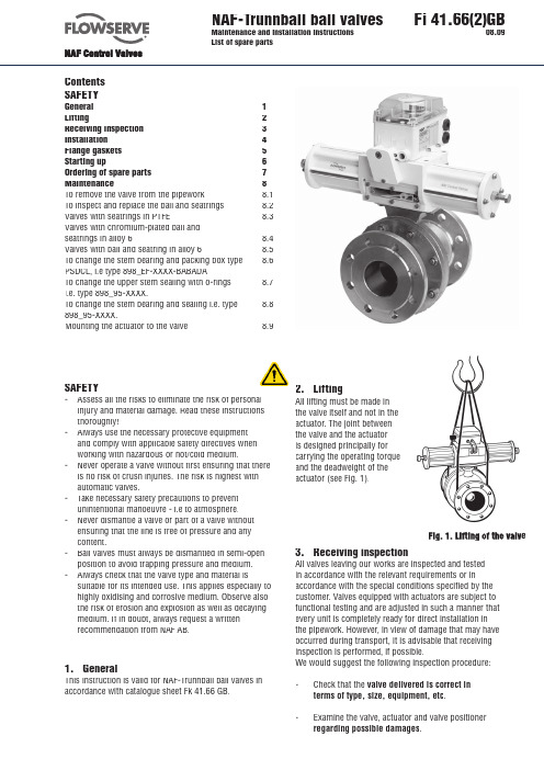
NAF-Trunnball ball valves Maintenance and installation instructionsList of spare parts Fi 41.66(2)GB08.09ContentsSAFETYGeneral 1 Lifting 2 Receiving inspection 3 Installation 4 Flange gaskets 5 Starting up 6 Ordering of spare parts 7 Maintenance 8 To remove the valve from the pipework 8.1 To inspect and replace the ball and seatrings 8.2 Valves with seatrings in PTFE 8.3 Valves with chromium-plated ball andseatrings in alloy 6 8.4 Valves with ball and seatring in alloy 6 8.5 To change the stem bearing and packing box type 8.6 PSDCL, i.e type 898_EF-XXXX-BABADATo change the upper stem sealing with o-rings 8.7 i.e. type 898_95-XXXX.To change the stem bearing and sealing i.e. type 8.8 898_95-XXXX.Mounting the actuator to the valve 8.9SAFETY- Assess all the risks to eliminate the risk of personal injury and material damage. Read these instructionsthoroughly!- Always use the necessary protective equipment and comply with applicable safety directives whenworking with hazardous or hot/cold medium.- Never operate a valve without fi rst ensuring that there is no risk of crush injuries. The risk is highest withautomatic valves.- Take necessary safety precautions to prevent unintentional manoeuvre - i.e to atmosphere.- Never dismantle a valve or part of a valve without ensuring that the line is free of pressure and anycontent.- Ball valves must always be dismantled in semi-open position to avoid trapping pressure and medium.- Always check that the valve type and material is suitable for its intended use. This applies especially to highly oxidising and corrosive medium. Observe also the risk of erosion and explosion as well as decaying medium. If in doubt, always request a writtenrecommendation from NAF AB.1. GeneralThis instruction is valid for NAF-Trunnball ball valves in accordance with catalogue sheet Fk 41.66 GB.2. LiftingAll lifting must be made inthe valve itself and not in theactuator. The joint betweenthe valve and the actuatoris designed principally forcarrying the operating torqueand the deadweight of theactuator (see Fig. 1).alve 3. Receiving inspectionAll valves leaving our works are inspected and testedin accordance with the relevant requirements or in accordance with the special conditions specifi ed by the customer. Valves equipped with actuators are subject to functional testing and are adjusted in such a manner that every unit is completely ready for direct installation inthe pipework. However, in view of damage that may have occurred during transport, it is advisable that receiving inspection is performed, if possible.We would suggest the following inspection procedure:- Check that the valve delivered is correct interms of type, size, equipment, etc.- Examine the valve, actuator and valve positioner regarding possible damages.4. InstallationBefore installing the valve, ensure that the pipework is free from impurities, that the pipe ends between which the valve is to be installed are parallel and are correctly aligned, and that the distance between the pipe ends corresponds to the valve length, including gaskets. The valve must not be used for drawing together or aligning incorrectly run pipes as this will cause needless loads on the valve and pipe which may lead to diffi cult damages during operation. See Fig. 2.Wrong installation Correct installation Fig. 2. Ensure that the pipe ends align and have thecorrect distanceNAF-Trunnball valves can be installed in any position and with optional fl ow direction.However, we recommend that, if installed in a horizontal run of pipe, the valve should be mounted with the stem pointing vertically upwards. If the valve is installed in a vertical run of pipe, the body half (2) according to fi g. 3 should be at the top to enable the ball and the seat ring to be replaced without the need for removing the valve from the pipework.The pipes should be supported on each side of the valve, in order to relieve the valve of loads and avoid vibrations.Locate the valve so that it will be easily accessible for inspection and service, particularly if the valve is equipped with an actuator and a valve positioner.5. Flange GasketsGaskets with sizes according to ANSI B16.5 1988, Table E1 Figure E2, SS 359 or DIN 2690 are recommended.6. Starting upBefore starting up, fl ush the pipework - with all valvesin the open position - so that any impurities that may damage the sealing surfaces of the valve and impede its operation will be fl ushed away.See also Fi 41.82 - Instruction Manual for NAF valve positioner giving useful hints for starting up. 7. List of Materials and Spare PartsItem No.Qty.Part Material 11Body EN 1.4408/CF8M21Body EN 1.4408/CF8M31Ball hard chrome EN 1.4408/CF8M/Hcr 42Seat ring Alloy 651Stem, assembly EN 1.446061Circlip Spring steel71Backing ring PTFE81Upper lid EN 1.443694Screw A4111Packing box PTFE/PTFE+25%C121Bushing PTFE+1.4401131Anti-friction washer EN 1.4436141Sealing ring PTFE1510Screw A4-801612Nut A4172Screw A4-80182Key A4191Ball EN 1.4408/CF8M201Ball Alloy 6212Seatring EN 1.4436/PTFE+25%C 221Bearing PTFE+1.4401232Trunnion plate EN 1.4470242Spring ASTM A316252Sealing ring PTFE+15%Graphite 261O-ring FPM281Spring ASTM A316291Supporting ring Spring steel301Washer A4311Supporting ring PTFE322O-ring EPDM332Bushing PTFE reinforced carbon 341Sliding washer PTFE reinforced carbon23127893456172223252415182813261211161424252342232343330296932312425252124430319Stem SealingAlloy 6PTFEType 898_EF-XXXX-BABADA Fig. 3NAF-Trunnball Spare partsStem sealings and seatrings versionswith o-rings type 898X9X-XXXX7. Ordering of Spare PartsWhen placing orders for spare parts, specify:1. Product code of the valve, incl. DN according toFk 41.66 and the manuf. No.specifi ed on theidentifi cation plate of the valve.2. Description of the part, item No and the quantityrequired - see table below.Ordering exampleFor NAF 8982EF-0200-BABADA, Manuf. No. 1234567Seat ring, item 4. Qty 2 pcs.Spare partsIten No Description Qty 150 200 250 300 400 450 500 600 7008006” 8” 10” 12” 16” 18” 20” 24” 28” 32”Stem sealing kit7 Supporting ring 1 pc X X X X X11 Packing box 1 pc X X X X X26 O-ring 1 pc X X X X X31 Supporting ring 1 pc X X X X X32 O-ring 2 pcs X X X x X33 Bushing 2 pcs X X X X X34 Sliding washer 1 pc X X X X X Spring kit28 Spring washer 4 pcs X X X X XMetaloplast bearing kit12 Metaloplast bearing 1 pc X X X X X22 Metaloplast bearing 2 pcs X X X X X X X X X X Bodyhalf sealing14 Bodyhalf sealing 1 pc X X X X X X X X X X Seatring4 Alloy 6 1 pc X X X X X X X X X X 20 PTFE 1 pc X X X X X X X X X X (2 pcs for each valve)Sealing behind the seatring25 Sealing 1 pc X X X X X X X X X X (2 pcs for each valve)Wave spring24 Wave spring 1 pc X X X X X X X X X X (2 pcs for each valve)Ball3 EN 1.4408 1 pc X X X X X X X X X X19 EN 1.4408/Hcr 1 pc X X X X X X X X X X20 Alloy 6 1 pc X X X X X X X X X X453. Shut off all compressed air connections and isolate all electrical connections to the actuator.4. Disconnect all compressed air lines and electric cables connected to the actuator.5. Loosen the fl ange joint between the valve and the pipework. Then lift out the valve. Don’t use the actuator for lifting. Apply all lifting forces tothe valve itself and not to the actuator - Fig. 1.N.B . In certain applications, the pipe can be discon- nected from one side of the valve, and the body half (2) - Fig. 3 - can be removed, without the need for removing the whole valve from the pipework.6. Mark the relative positions of the body halves by centre-punching before the dismounting, since the pattern of the holes drilled in the valvefl ange and pipe fl ange may vary.Fig. 4. Lifting the ball with the valve in closed posi- tion - here with the valve on a work bench. It can also be done with mounted actuator and the body (1) mounted in the pipework.8. MaintenanceMany valves are installed in such locations that their performance is of decisive importance to the entire process. Such valves should be inspected regularly and any faults should immediately be corrected.8.1 To remove the valve from the pipeworkNo special tools are needed for the inspection and maintenance.1. Ensure that the recommended spare parts and gaskets for the pipe fl anges are available.2. Close the valve. Before dismounting the valve, make certain that it is completely empty . Operate the valve several times between the open and closed positions to ensure that the space between the valve body and ball is not under pressure.Caution! The liquid in the valve may be harmful.8.2 To inspect and replace the ball and seatrings 1. The actuator does not need to be removed for replacing the seatring and ball.2. Operate the valve to make certain that it is completely empty . Close the valve.3. Remove the bodyhalf (2).4. Remove the ball and the trunnion plates - easy to do when the valve is in closed position.5. Remove the trunnion plates and the metaloplast bearing from the bearing journal of the ball.6. Carefully inspect the ball and the seatrings.7. Clean all parts carefully. First use hot water and then, if necessary, some degreasing compound. Do not scrape any machined surfaces with hard tools.8.3 Valves with seatrings in PTFE1. To ensure good tightness of the valve, change the seatrings, wave springs and sealings if they are worn or damaged.2. Mount the wave spring and sealing ring (pos 24 and 25) behind the seatring (pos 20).3. Inspect the ball. Minor damage to the sealing surface can be removed by polishing with fi ne emery cloth. If the ball has major damages, it must be replaced to ensure satisfactory tightness.4. Change sealing ring (14) between the two body- halves.5. Change the metaloplast bearing in the trunnion plates.6. Mount the bearing plates on the bearing journal of the ball.7. Coat the ball with Molycote U. If the valve is intended for service in an oxygen system, the ball can be coa- ted with silicone grease, which is approved for oxygen applications.8. Lubricate all stainless steel bolts with suitable grease, i.e. Crane Packings’s Thread-Grade or Gleitmo 600.9. Mount the ball and the bearing cage in the bodyhalf (1) and then the upper bodyhalf (2). Make sure that the centrepunch marks made according to section 8.1 item 6 are lined up. Tighten the bolted joint of the two bodyhalves alternately in several stages and tighten them fi nally as per the table below.10. Torque for tightning of the bolted joint:11.Operate the valve between closed and open positions.12. If possible, pressure test the valve with water to check its tightness - Fig. 5. Make sure that the c avities of the valve are properly fi lled with water before the pressure testing. The valve should be pressure tested as follows: Open valve: PN x 1,5Closed valve: Max dp x 1,1Bolt Torque NMBolt Torque NmM1276UNC 1/2”89M16187UNC 5/8”175M20364UNC 3/4”308M24629UNC 7/8”493UNC 1”73768.4 Valves with chromium-plated ball and seatrings in alloy 61. Check the sealing surfaces of the seatrings.A groove on the inside of the ring facilitates with- drawal. Minor damage to the rings can be polished with fi ne emery cloth. Check the rings on a face plate to ensure that they are perfectly fl at. Do not lap the rings and the chromium-plated ball together. Change the rings if they are severely damaged.2. Inspect the sealing surface of the ball. Minor damage may be polished with fi ne emery cloth. If the existing ball must be used for a furtherperiod of time, remove all sharp edges, dents and irregularities with a fi ne fi le or emery cloth. Check the circularity of the ball. The tolerance is 0.04 mm. If the ball is seriously damaged, it must be replaced.3. Mount the wave spring and the sealing ring (24 and 25) behind the seatring.4. Change the sealing ring (14) between the bodyhalves.5. Lubricate the ball with a suitable grease, such as Molykote U.6. Continue assembling the valve as described in section 8.3 item 8-12.Valve open Valve closedSealing fl angeWaterFig. 5. Pressure test of the valve with water8.6To change the stem bearing and sealing on valves with packing box type PSDCL (DN150-DN400) i.e. type 8982EF-XXXX-BABADA1. Dismount the actuator. Remove the screws that from the underside of the mounting plate of the valve keeps the actuator in place.2. Lift off the actuator from the valve. Remove the keys.3. Dismount thte valve according to section 8.2.4. Remove the circlip (6), loosen the screws (9) and remove the upper lid (8). Note! The upper lid is prespringloaded.5. Remove the springs (28).6. Press the stem down into the body and remove it.7. Pick up the anti-friction washer (13), supporting ring (7), o-ring (26) and packing box (11).8. Dismount the bushing (12) by pressing it into the body.9. Mount a new bushing (12) by pressing it up through the body.10. Lubricate a new packing box (11) with silicone grease before you press it down into the body. Note that the broadest of the 5 rings should be on top, see fi g 3 on page 3.11. Mount the stem by pressing if from the inside of the body and out.12. Mount the supporting ring (7) in the anti-friction washer (13), lubricate a new o-ring (26) with silicone grease and mount it in the anti-friction washer. Mount the anti-friction washer with the o-ring downwards against the valve.13. Mount the remaining parts in reverse order from item 5 to 1.8.5 Valves with ball and seatrings in alloy 6.1. The instructions for these valves are the same as those in section 8.4 above.2. If the sealing surfaces are damaged, we recom- mend that the valve is returned to NAF for repair. This applies especially if the ball must be ground before l apping. Assemble the valve before dispat- ching it to NAF.3. The ball and seat rings can be temporarily renova- ted by lapping them together. This can be done manually with a compound with grit size 200. Take great care to ensure that the ball and seat rings do not become oval.4. Balls in alloy 6 must be carefully cleaned andlubricated before they are mounted. Use a suitable solvent for cleaning. Then lubricate the ball with silicone grease, such as Molykote Dow Corning FS3452. The coat of grease must be very thin. Then polish the ball with chamois leather or apiece of soft cloth.WaterWat8.7 Change of the upper stem sealing with o-rings(DN450-DN800) i.e. type 898295-XXXXChange the upper o-ring (32) if the stem sealing is leaking. It is not necessary to remove the valve from the pipe-works. Change the complete stem bearing according to section 8.8 at the next service. Make sure that the valve is pressureless.1. Dismount the actuator. Remove the screws thatfrom the underside of the mountingplate of thevalve keeps the actuator in place.2. Lift off the actuator from the valve. Remove thekeys.3. Remove the circlip (6) and the supporting ring(29).4. Loosen the screws (9) and remove the washer(30) and the anti-friction washer in PTFE (31).5. Change the upper o-ring sealing (32). Lubricatethe new ring with silicone grease before it ismounted.6. Mount in reverse order.8.8 Replacement of stem bearing and sealing(DN450-DN800) i.e. type 898295-XXXX Dismount the valve from the pipeworks. Please note the instructions in sections 2 and 8.2 concerning lifting and emptying of the valve.1. Remove the actuator as described in section8.7, item 1 and 2.2. Remove the Circlip (6) and supporting ring (29).3. Loosen the screws (9) and remove the washer(30) and the anti-friction washer of PTFE (31).4. Dismount the valve according to section 8.2.5. Press the stem down into the body and removeit.6. Pick up the upper o-ring (32).7. Push up both the bearing bushings (33) and theintermediate o-ring (32).8. Mount new bushings and o-rings after they havebeen lubricated with Silicone grease. Changealso the sliding washer (34) on the stem.9. Mount the stem and the other parts in thereverse order.10. Mount the valve according to section 8.3.Before that consider to change the seatrings orlapping of the seatrings and ball.11. If possible, pressure test the valve and retightenthe bolts according to section 8.3.8.9Mounting the actuator to the valve1. Mount the actuator. The actuator may be mountedeither in line with the connected pipes or transversely to them. For mounting in line with the connectedpipes an intermediary plate is required2. Ensure that both the valve and the actuator are inthe closed position before mounting the actuator.The valve is in the closed position when thekeyway on the stem is in the direction of fl ow.(An actuator which uses compressed air to closethe valve and a return spring to open the valveshould be mounted with the actuator and valve in theopen position.)N.B. The direction of closure must always beclockwise, as viewed from the actuator.3. Before fi tting a new actuator, check that theactuator slides easily onto the stem when thekeys are not fi tted. Check also that the keys fi tfreely into the keyways in the hollow shaft of theactuator. Deburr if necessary. Lubricate the hollowshaft of the actuator and push it in over thethreaded sleeve. Mount the actuator onto the stem.Mount the bolts and nuts, and tighten them.4. Check the function and check that the end stopshave been correctly preset. If necessary, makeadjustments.If any accessories such as valve positioner orlimit switches should be mounted, please see thecorresponding manufacturer’s instructions forinstallation and adjustment.7NAF ABSE-581 87 Linköping Telephone +46 13 31 61 00Facsimile +46 13 13 60 54e-mail info@naf.seWebsite: www.naf.seISO 9001 Certifi edWe reserve the right to design modifi cationswithout prior notice8。
MSA球阀安装操作手册中英对照
MSA, a. s. ASSEMBLY AND OPERATING Sheet No.: 1/23 DOLNÍ BENEŠOV INSTRUCTIONS Issue No.: 6Assembly and Operating Instructions组装和操作说明BALL VALVES球阀此文件是MSA 独有的知识产权,未经MSA技术部门经理同意禁止将此文件复印或提交给其他组织。
This document is an exclusive intellectual property of MSA, a.s. Dolni Benesov. Making copies of this document for other organizations, or submitting it to other organizations without consent of production technical director is forbidden.Manufacturer: MSA, a. s.Hlucinska41DolniBenesov74722CzechRepublic Division Name Date SignatureMade by: Ing. Jindrich GratzaPavel SchiedekDesigners5. 3. 2004Tested by: Ing. Jan KalabzaChief Designer 5. 3. 2004DOLNÍ BENEŠOV INSTRUCTIONS Issue No.: 6 Contents:内容1. 介绍Introduction (3)2. 储存Storage (3)3. 安装Installation (4)4. 操作Operation (6)5. 调试Adjustment (10)6. 故障诊断Trouble Shooting (11)7. 修理Repairs (13)Annexes:附件č. 1 球阀的操作Manipulation with Ball valve (BV) (15)č. 2 球阀型式BV Types (17)č. 3 球阀焊接的温度限制―管线Temperature Restriction for BV Welding – Pipeline (18)č. 4 球阀压力引出位置Position with Pressure Extraction (19)č. 5 球阀安装到管线上BV Installation into Pipeline (20)č. 6 球阀密封元件的更换Replacement of BV Sealing Elements (21)č. 7 球阀执行机构的更换Replacement of BV Actuator (22)DOLNÍ BENEŠOV INSTRUCTIONS Issue No.: 61. 介绍INTRODUCTION1.1 球阀是设计用以全关或全开两位式控制流经管线的介质流动的工业装置。
- 1、下载文档前请自行甄别文档内容的完整性,平台不提供额外的编辑、内容补充、找答案等附加服务。
- 2、"仅部分预览"的文档,不可在线预览部分如存在完整性等问题,可反馈申请退款(可完整预览的文档不适用该条件!)。
- 3、如文档侵犯您的权益,请联系客服反馈,我们会尽快为您处理(人工客服工作时间:9:00-18:30)。
Product Manual
- Operation and Maintenance Manual Product Name:API 6D Ball Valve
January 2012
1Scope
This manual covers manually/motor/pneumatic operated seat supported /trunnion supported ball valve having tow/three pieces body with nominal sizes DN 15mm-1200mm (1/2”-48”) and class ranges PN1.6MPa-10MPa(ANS1 class 150-2500).
Valve ends may be threaded, flanged, butt-welded or socket
2 Applications
2.1 Ball valves are used to open/close the flow in pipeline.
2.2 The nature of applicable fluid depends on valve material:
2.2.1 Carbon steel valve applies to non-corrosive fluid, such as water, vapor or oil etc. 2.3 Temperature range depend on sent material:
PTFE ≤130℃
RPTFE ≤160℃
PPL ≤300℃
NYLON ≤121℃
3. standard:
Basic design API 6D-2008
Inspe crlon tesring BS EN 12266.1-2003
End flange ASME B16.5-2009
TEMP. & PRESSURE ASME B16.34-2009
Face toface ASME B16.10-2009
Main parts and materials ASME materials, see Table 1
Figure 1:Trunnion Ball Valve
4 Structure
4.1 Ball Valve structure is shown in Fig. 1.
4.2 List the major components and materials shown in Table 1:
Table 1: Major Parts and Materials
-29℃~38℃working pressure(bar)
50℃working pressure(bar)
100℃working pressure(bar)
121℃working pressure(bar)
6 Operation
The valve can be manually operated by using the handle for manually operated valves or motor-operated by the electric actuator for motor operated valves or pneumatic operated by pneumatic actuator for pneumatic operated valves. The valve open or closes by turning the ball. Clockwise turning to 90ºresults in valve open.
6.1 The manually operated valve is opened when the handle and the position mark on stem end are parallel to pipeline. When that is perpendicular to the pipeline, the valve is closed.
6.2 For motor/pneumatic operated valves, valve open/close is indicated by the positioner on the electric/pneumatic actuator.
7 Storage, maintenance, installation and service
7.1 The valve should be stored in dry room with good ventilation. Valve ends should be covered.
7.2 For valve stored for a long period of time, regular checkup is required to ensure that the valves are in good conditions. Foreign particles should be removed and special care should be taken to keep the valve seat sealing surface clean and prevent any damage of sealing surface.
7.3 Check the conformance of valve identification to the service requirements prior to installation.
7.4 Check the cleanness of the valve cavity and sealing surface and sealing surface and wipe off any dirt with white cloth prior to installation.
7.5 Before installation, the tightness of packing should be checked to ensure that sealing is secured without affecting the turning of stem.
7.6 The valve shall be in full open position when conducting system or pip line pressure test after the valve installation.
7.7 Ball valve shall be in full open or full close position while in service. partial opening for controlling the flow is not allowed.
7.8 Manually operated valve should be operated by using the handle. Use of lowers or other tools is not allowed.
7.9 Valve in service should be examined at prescribed intervals to see whether the wear of sealing surface or stem occurs and the gasket or packing fails. Repair or replacement shall be carried out timely if necessary.
7.10 “Electric valve actuator instruction manual” and “Pneumatic valve actuator instruction manual” should be referred with regard to the storage, maintenance, installation and service for motor-operated valve and pneumatic-operated valve respectively.
8 Possible troubles, causes and solutions see table
9 Guarantee
Guarantee period is one year after service date no later than 18 months after delivery date. Valve failure due to material defectives, manufacturing problems, design unreasonable or any damage under normal operating conditions will be repaired or parts replaced free of charge by manufacturer within the guarantee period.。