Linear-LTC3588-1压电能量收集电源方案
一种毫微功耗的微弱能量收集电路设计
一种毫微功耗的微弱能量收集电路设计作者:韩晓婧张子佑刘锋来源:《物联网技术》2016年第09期摘要:随着物联网的发展以及传感器的广泛使用,以电池为主的无线传感器供电方式因电池的固有缺陷而备受关注。
将环境中的微弱能量转化为电能可以实现无线传感器网络节点自供电。
文中设计了一种毫微功耗的微弱能量收集电路,实验结果表明,通过收集环境中的微弱能量能够取代电池或者利用收集的能量给电池充电,从而延长电池的寿命,以解决无线传感器网络节点的供电问题。
关键词:低功耗;无线传感器;能量收集电路;自供电中图分类号:TN712.5 文献标识码:A 文章编号:2095-1302(2016)09-0090-040 引言环境中的微弱能量非常微小,但随着电子技术和制造业的发展,传感器正常工作的功耗也越来越低,收集环境中的微弱能量完全能够满足传感器正常工作的需求。
通过对微弱能量的收集来取代电池或者将收集的电能为电池供电是解决传感器供电问题的一种有效途径。
在过去的几年间,物联网技术得到了高速发展,而电源技术的进步却小得多,电池在能量的存储密度上没有太大提高[1]。
传统的无线传感器依靠电池供电来工作并以无线方式发送其测试数据[2]。
这种供电方式的优点在于比较可靠,但缺点是传感器网络节点的使用时间长短取决于供电电池的寿命[3]。
因此,研究者希望能够实现传感器的自供电,利用环境中的微弱能量取代电池或延长电池的寿命[4,5]。
环境中微弱能量的收集由于具有收集方便、来源广泛等优点,得到了研究者的极大关注,成为国际上的研究热点之一[6,7]。
本文设计了一种毫微功耗的微弱能量收集电路,利用LTC3588-1、LT3464、TLV61225三种芯片作为核心电压变换电路;LTC4071芯片为核心的充电控制电路;TPL5100芯片为核心输出控制电路设计微弱能量收集电路,将收集到的电能存储到储能装置或者直接给负载供电。
将能量收集器接入电路,验证微弱能量收集电路将收集的电能储存在锂电池中的可行性以及电路自身的低功耗。
linearltc压电能量收集电源方案
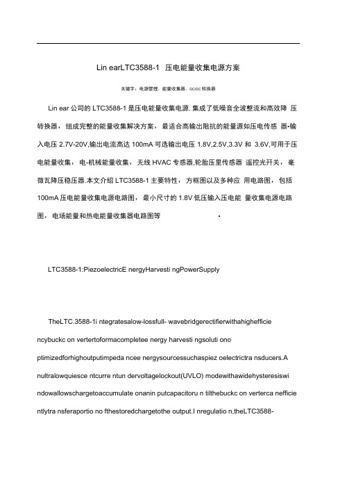
Lin earLTC3588-1 压电能量收集电源方案关键字:电源管理,能量收集器,DC/DC转换器Lin ear公司的LTC3588-1是压电能量收集电源,集成了低噪音全波整流和高效降压转换器,组成完整的能量收集解决方案,最适合高输出阻抗的能量源如压电传感器•输入电压2.7V-20V,输出电流高达100mA可选输出电压1.8V,2.5V,3.3V 和 3.6V,可用于压电能量收集,电-机械能量收集,无线HVAC专感器,轮胎压里传感器遥控光幵关,毫微瓦降压稳压器.本文介绍LTC3588-1主要特性,方框图以及多种应用电路图,包括100mA压电能量收集电源电路图,最小尺寸的1.8V低压输入压电能量收集电源电路图,电场能量和热电能量收集器电路图等•LTC3588-1:PiezoelectricE nergyHarvesti ngPowerSupplyTheLTC.3588-1i ntegratesalow-lossfull- wavebridgerectifierwithahighefficie ncybuckc on vertertoformacompletee nergy harvesti ngsoluti ono ptimizedforhighoutputimpeda ncee nergysourcessuchaspiez oelectrictra nsducers.A nultralowquiesce ntcurre ntun dervoltagelockout(UVLO) modewithawidehysteresiswi ndowallowschargetoaccumulate onanin putcapacitoru n tilthebuckc on verterca nefficie ntlytra nsferaportio no fthestoredchargetothe output.I nregulatio n,theLTC3588-1en tersasleepstate in whichboth in puta ndoutputquiesce ntcurre ntsare mini mal.T hebuckc on vertertur nsonan doffas neededtoma intain regulati on.Fouroutputvoltages,1.8V,2.5V,3.3Va nd3.6V,arepi nselectablewithupto100m Aofcontinu ousoutputcurre nt;however,theoutputcapacitormaybesizedtoservice ahigheroutputcurre ntburst.A nin putprotectivesh un tsetat20Ve nablesgreatere n ergystorageforagive namoun tofi nputcapacita nee.LTC3588-1主要特性:—NoLoad) 950nAln putQuiesce ntCurre nt(Outputi nRegulatio n450nAI nputQuiesce ntCurre nti nUVLO2.7Vto20VI nputOperati ngRa ngeIn tegratedLow-LossFull-WaveBridgeRectifierUptolOOmAofOutputCurre nt SelectableOutputVoltagesof1.8V,2.5V,3.3V,3.6VHighEfficie ncyl ntegratedHystereticBuckDC/DCIn putProtectiveShu nt —Upto25mAPull-Do wn atVIN> 20V WideI nputU ndervoltageLockout(UVLO)Ra ngeAvailablei n10-LeadMSEa nd3mmx3mmDFNPackagesLTC3588-1 应用:PiezoelectricE nergyHarvesti ngElectro-Mecha nicalE nergyHarvesti ngWirelessHVACSe nsors MobileAssetTracki ngTirePressureSe nsors BatteryReplaceme ntforl ndustrialSe nsors RemoteLightSwitchesStan dal on eNa nopowerBuckRegulator著一m函1.LTC3588匕8斎函」sm ApieicE一鱼S-rrl n E a yHaw邕?壬『OCT函 2.L T C3588—l 00m A te [>^K *t >[>M函i图3.LTC3588-13.3V 压电能量收集电源电路图:给带无线发送器的微处理器和 50mA 瞬态负载供电.P 旧电 SYSTEMS T220-.M*^3X_IDI —图4.最小尺寸的1.8V 低压输入压电能量收集电源电路图'h {OPTIONAL}VlH PGCXJDV||Q LTCK3B-1CAPsw D3 VoufDO1O|1FprePGOOOLTC3588-1$w^bur、蟻bl 1帕&0PIEZO STS T230-A4-M3XTtzu=1=T1-q —刖M|lF &vPflPZ? KWCW*|hUC358B-1.B . ¥IIE ■aiiiDI&3GND—■ JU -10UHI J-111FT2Li 卯—r- ?5V I -------1±图5.采用单个压电晶体和自动加电次序的双电源电路图iMU 比4优罚TWIflUHVOUTipF 6V—r^Ev1O0^亠*髦"F "T BYr1OyF25V I ----------------47|f图6.带备份电池的压电能量收集器电路图图7.AC 火线供电的3.6V 降压稳压器,大输出电容支持重负载PANELS ARE PLACED G bFROM T x4' FLUQRfSCFFJT LiflHT FIXTURESGOPPtR 用MEL(情綁刊IDANGER! HIGH VOLTAGE'COPPER PA 忡EL(12* x 24f \—F*GOODPGOQD9V ' BAntHVP1E2O SVSTEMS T2SOW-503XP21p 竝VlHPGOODITG33A8-1CAP SWV|W2Van00P22GHDPGOODPZ2PGOODlTCJ5B8-tswV,-,-vgyr□ lDO RND5p7?v-iPGOODLTO5^0-1GAP5W%V QUTBlI (X JHJ —*1O^F "T" SV图8.电场能量收集器电路图St _L5VT0 f6V•…SOUR PANfL rao5M4X&FrrIPF■VvVT BATTERYII%PiJOODLTG3W1GAP SWy IV3V CVT0001GNDiPG3OD5* 2.7V 蚀FX5V NESS SUPER W^ACITOR_ £5HSR-ODa30O^M2fl7图9.5-16V太阳能供电的2.5V电源,其超大电容增加输出能量存储和备份电池IPG-1 THERMALI GEMERATORMi 61-1,0-127-1.27I (TELLUflEX)—5,4VH工工工[---------1P22%卩GOODUC3506-1CAP畑V OUTDO01GUO跡47pF2.5V图10.热电能量收集器电路图。
基于传感器的新型网络节点设计
以到达±2.5℃。除此之外 ,无线发射模块大部分都是选用 CC2420芯
压 电自发 电单元产生的交流电信号需经滤波 、桥式整流和 DC— 片 ,这种芯片功耗低 、体积小 ,外部工作电压为 3.3V。由于无线传感
DC电压变换单元电路后 ,将输出的电信号通过储能元件储存起来 网络节点中选用的传感器模块和微处理器模块 ,其工作电压都是
压 型转 换 器 、全 波 桥 式 整 流器 可 以 大 大 降低 损 耗 ,压 电传 感 器 在 环 化 为 3.3V 电压来 提 供给 无 线传 感 网络 节 点充 足 电源 。
境 中所 收集 到 的振 动 能量 通 过 能量 转 换 成调 节 好 的输 出 ,就 可 以很
3结束 语
好地为传感器 、微控制器、无线传输组件 、数据转换器供电。
供查询依据 ,并为专业组 的 日常工作安排提供依据。根据不 同类型 【M].北京 :人 民 邮 电 出版 社 ,2012.
分发电厂,技术监督模块可结合实际进行布置 ,结构如 图 4所示。 [2]GB26164.1—2010.电业 安全 工作 规 程(第 1部 分).热 力和 机械 .
电式 能 量 收集 电源 、压 电发 电 单元 、传 感器 模 块 、无 线 发 射 模 块 、微 [2】宋世 鹏 .基 于 ATmega128L上 的 无 线传 感 ቤተ መጻሕፍቲ ባይዱ网络 节 点设 计 [D].西 安
处 理器 模 块这 五 大部 分 组成 。节 点 框 图如 图 1所示 。
电子 科 技 大 学 :软件 工程 ,2013.
下面分别阐述传统 的能量储 存和收集装置 ,然后进行 比较分 2—5.5V之 间 ,在这 个 时候 外部 电压 为 3.3V。其 最 大 电流仅 为 4uA,因
LinearLTC3588~1压电能量收集电源方案

Lin ear LTC3588-1压电能量收集电源方案关键字:电源管理,能量收集器,DC/DC转换器Linear公司的LTC3588-1是压电能量收集电源,集成了低噪音全波整流和高效降压转换器,组成完整的能量收集解决方案,最适合高输岀阻抗的能量源如压电传感器•输入电压2.7V-20V,输岀电流高达100mA,可选输出电压1.8V, 2.5V, 3.3V和3.6V,可用于压电能量收集,电-机械能量收集无线HVAC传感器,轮胎压里传感器,遥控光开关,毫微瓦降压稳压器.本文介绍LTC3588-1主要特性,方框图以及多种应用电路图,包括100mA压电能量收集电源电路图,最小尺寸的1.8V低压输入压电能量收集电源电路图,电场能量和热电能量收集器电路图等.LTC3588-1: Piezoelectric Energy Harvesting Power SupplyThe LTC.3588-1 integrates a low-loss full-wave bridge rectifier with a high efficiency buck converter to form a complete energy harvesting solution optimized for high output impedance energy sources such as piezoelectric transducers. An ultralow quiescent current undervoltage lockout (UVLO) mode with a wide hysteresis window allows charge to accumulate on an input capacitor until the buck converter can effi ciently transfer a portion of the stored charge to the output. In regulation, the LTC3588-1 enters a sleep state in which both input and output quiescent currents are minimal. The buck converter turns on and off as needed to maintain regulation.Four output voltages, 1.8V, 2.5V, 3.3V and 3.6V, are pin selectable with up to 100mA of continuous output current; however, the output capacitor may be sized to service a higher output current burst. An input protective shunt set at 20V enables greater energy storage for a given amount of input capacitance.LTC3588-1主要特性:950nA Input Quiescent Current (Output in Regulation - No Load)450nA Input Quiescent Current in UVLO2.7V to 20V Input Operating RangeIntegrated Low-Loss Full-Wave Bridge RectifierUp to 100mA of Output CurrentSelectable Output Voltages of 1.8V, 2.5V, 3.3V, 3.6VHigh Efficiency Integrated Hysteretic Buck DC/DCInput Protective Shunt - Up to 25mA Pull- Down at VIN > 20V Wide Input Undervoltage Lockout (UVLO) RangeAvailable in 10-Lead MSE and 3mm x3mm DFN Packages LTC3588-1 应用:Piezoelectric Energy HarvestingElectro-Mechanical Energy HarvestingWireless HVAC SensorsMobile Asset TrackingTire Pressure SensorsBattery Replacement for Industrial SensorsRemote Light SwitchesStandalone Nanopower Buck Regulator6恤10, 血IIHErUIAl FUILE 31 01 M)L} "T —6V图2.LTC3588-1 100mA 压电能量收集电源电路图图1.LTC3588-1方框图 100mA Piezoelectric Energy Harvesting Power Su 叩ly ACVAWCEO CERAMETPICS PFC-WU BUCK :CCNrROLCSIORAGE25Y rIQpH---- -------------------- 畑 TI 丄< 砒 _H 刖nMi■ ] OUTPUT - ~ VOLTAGESELECTPGOOi?PGOODGWFRFJGR0ALD&APREFERENCE PZ1 PZ2v,Nsw n«&se -i如CAPPGOOO VlPiz00. Q1GRID工图 3.LTC3588-1 3.3V 压电能量收集电源电路图:给带无线发送器的微处理器和50mA 瞬态负载供电.图5.采用单个压电晶体和自动加电次序的双电源电路图PZ1VinmPGOODCAPLTG35W-1 鬧畑hiv tMHU ID9GMDCO^EENhMICROPROCESSORL.・ OpF I --------------------- ' 丄斗卉4 uS图4.最小尺寸的1.8V 低压输入压电能量收集电源电路图眺JO £*STLUSPZ2PZI PGODDDO10pF25V pdOO 序一1—MF "Rev rLTCJsea-iCAP SW图8.电场能量收集器电路图图6•带备份电池的压电能量收集器电路图图7.AC 火线供电的3.6V 降压稳压器,大输出电容支持重负载円㈣:”DANGER HIGH VOLTAGE 1150k信 DkI------------- z\l20VAC创用 1 5Qk 15CH<-T-弭9VBAHEHVPILZO SVSTEMS T22O-W-5WXtR05H40C&?7^rtFPANELS ARE PLACED G bFROM ?' x4' FLUORfSCEM LIGHT FiZTUFtESCCPPfR PAF1ELCOPPER 朋毗LP22V|kjPGOODITC358 &>1CftpSW V|H2VtMJT口DOGHCIF'A QOCP71 P7? V.|PGOODLTC3&B0-13Wv12 VOUTtnGMDPGOOD±±GU二询s图10.热电能量收集器电路图图9.5-16V 太阳能供电的2.5V 电源,其超大电容增加输出能量存储和备份电池10012I Pfi-1 THERMAL |鉅碰RATOR fflie 1-1,0-127-157I llfLLJflEKi丁阳 •ipf ■仙mi -w>5V TO 16VSOLAR PAN5LSVRAnERY[R06H4X5FTRM : HE255 S' PER TAPACiTOR TAW :RF1-'00300-^237—^— i OpfPGO QDP12WinPG&ODLTC358 时CAPBVJ恤0001 GND—團 - |'"4.7|jF 工PZ1PZ2 wPG-OTDLTG35S8-1CAPSW 畑VOUT :DOD1GNDPGOOO。
3588说明书

本模块采用凌利尔特公司的能量收集芯片LTC3588-1对压电材料(如压电陶瓷、压电纤维)产生的能量收集应用。
LTC3588-1芯片的输入电压范围为2.7V~20V;通过短路帽的选择,输出电压可以设定为1.8V、2.5V、3.3V或3.6V(默认)。
功能:
1.将压电材料产生的电能存储在超级电容中;
2.当输出电压稳定(即超级电容充满),打开开关,发光二极管点亮;
3.充电过程中,通过电压表头可以观察到输出电压的电压值;
图1为悬臂梁结构能量收集实验平台,其中能量收集器采用两片并联的压电陶瓷片,尺寸为38mm×30mm×0.5mm。
图1 悬臂梁结构能量收集实验平台
经试验,在处于谐振频率,压电陶瓷开路电压峰峰值约为12V时,充电耗时约27分钟。
在0~2V时,电压变化十分明显;在2~3.6V时电压变化相对缓慢。
图2为充电完成效果图,图3为充电完成后打开开关效果图。
图2 充电完成打开开关效果图
图3 充电完成后打开开关效果图。
LINEAR LTC4071_LTC3588 说明书

36 | October 2010 :LT Journal of Analog InnovationTrue Grid Independence: Robust Energy Harvesting System for Wireless Sensors Uses Piezoelectric Energy Harvesting Power Supply and Li-Poly Batteries with Shunt ChargerGeorge H. Barbehenncapabilities of the system. L i kewise , the sensor /transmitter may need to operate at times when no energy is harvested. Finally , if the stored energy is depleted and the system is going to shut down , the system may need to carry out housekeep-ing tasks first. This may include a shut-down message , or storing information in nonvolatile memory. Thus , it is important to continuously gauge available energy.COMPLETE ENERGY HARVESTING SYSTEMFigure 1 shows a complete system imple-mentation using an LTC3588-1 energy harvester and buck regulator IC , two LTC4071 shunt battery chargers , two GM BATTERY GMB301009 8m A h batter-ies and a simulated sensor-transmitter modeled as a 12.4m A load with 1% duty cycle. The LTC3588-1 contains a very low leakage bridge rectifier withEnergy harvesting alone often does not produce sufficient power to continu-ously run the sensor-transmitter—energy harvesting can produce about 1m W–10m W , where the active sensor-transmitter combination may need 100m W–250m W. Harvested energy must be stored when possible , ready for use by the sensor /trans-mitter , which must operate at duty cycle that does not exceed the energy storageThere is an emerging and potentially large market for wireless sensors. By their very nature, wireless sensors are chosen for use in inaccessible places, or for applications that require large numbers of sensors—too many to easily hardwire to a data network. In most cases, it is impractical for these systems to run off primary batteries. For example, a sensor for monitoring the temperature of meat as it is shipped would need to bemounted in a tamperproof way. Or, HVAC sensors that are mounted on every source of conditioned air would be far too distributed to feasibly use batteries. In these applications, energy harvesting can solve the problem of providing power without primary batteries.Figure 1. Complete piezo-based energy harvesting system is independent of the grid. This design uses thin film batteries to gather energy collected by the piezo for a wireless sensor transmitter, which operates on a 1% duty cycle.October 2010 : LT Journal of Analog Innovation | 37design ideasI I V V DUTYCYCLE I AVG SENSORIN AVG OUTBUCKQ BUC =••+()(ηK )I mAVVµA µAAVG =••+≅124923308500098860.....Harvested energy can drive the sensor-transmitter at a 0.5% duty cycle with about 120µA left to charge the batter-ies. The GMB301009 batteries have a capacity of 8m A h , so they completely charge from empty in about 75 hours.Discharging-SendingWhen the PFCB-W 14 is not deliver-ing power , the voltage at V IN drops to approximately:8466275...+=V So the reflected load current calculation changes to:I mAVVµA µAAVG =••+≅1247533085000981578.....The quiescent current of the buck regu-lator is higher because the regulator must switch more often to regulate from 7.5V versus 9.2V. At 78µA , with no energy harvested , the battery is discharged in approximately 115 hours. This indicates a charge storage capacity of >8.95m A h . These batteries when brand new could store approximately 12% more charge than rated.A more serious problem is what happens when the battery is fully discharged. If current is drawn after the state of charge reaches zero , and the battery voltage dropsset with a self-clocked digital timer and a MOSFET switching a 267Ω resistor.MODES OF OPERATIONThis system has two modes of opera-tion: charging-sending and discharging-sending. In charging-sending mode , the batteries are charged while the sensor-transmitter presents a 0.5% load. When discharging , the sensor-transmitter is operating , but no energy is being harvested from the PFCB-W 14.Charging-SendingWhen active , the PFCB-W 14 delivers power at an average of approximately 9.2V × 180µA ≈ 1.7m W. The available current must charge the battery and operate the buck regulator driving the simulated sensor-transmitter. The active sensor-transmitter draws 12.4m A × 3.3V ≈ 41m W at around 1% of the time , or about 0.41m W on average , leaving some current to charge the battery. Taking into account the 85% efficiency of the LTC3588 buck reg-ulator , assuming an average V IN of 9.2V (see Figure 2), and a buck quiescent current of 8µA , the average current consumed by the system without charging the battery is:inputs at PZ 1 and PZ2 and outputs at V IN and GND. V IN is also the input power for a very low quiescent current buck regulator. The output voltage of the buck regulator is set by D 1 and D0 to 3.3V.The LTC3588 is driven by an Advanced Cerametrics Incorporated PFCB-W 14piezoelectric transducer , which is capable of generating a maximum of 12m W. In our implementation , the PFCB-W 14 provided about 2m W of power.The LTC4071 is a shunt battery charger with programmable float voltage and temperature compensation. The float voltage is set to 4.1V , with a tolerance on the float voltage of ±1%, yielding a maximum of 4.14V , safely below the maximum float allowed on the batter-ies. The LTC4071 also detects how hot the battery is via the NTC signal andreduces the float voltage at high tempera-ture to maximize battery service life.The LTC4071 is capable of shunt-ing 50m A internally. However ,when the battery is below the float voltage , the LTC4071 only draws ~600n A of current from the battery.The GM BATTERY GMB301009 batter-ies have a capacity of 8m A h and an internal series resistance of ~10Ω.The simulated sensor-transmitter is modeled on a Microchip PIC 18LF 14K22 and MRF24J40MA 2.4GH z IEEE stan-dard 802.15.4 radio. The radio draws 23m A in transmit and 18m A in receive. The model represents this as a 12.4m A , 0.98% duty cycle (2ms/204ms) load ,With a few easy-to-use components, it is possible to build a complete compact energy-harvesting power subsystem for wireless sensor-transmitters.V IN 2V/DIVI LOAD 5mA/DIV 0V , 0A4ms/DIVFigure 2. Charging with sensor-transmitter load38 | October 2010 :LT Journal of Analog InnovationMEASURED RESULTSThe system shown in Figure 1 was measured in both operating modes discharging-sending (Figure 3) and charging-sending (Figure 4).Discharging-SendingIn Figure 3 the voltages of the two bat-teries BAT 1, BAT2 and V BUCK are plot-ted against time with the batteries supplying all the system energy , none from the PFCB-W 14 piezo.The batteries slowly discharge until BAT 1 activates the LBO threshold of its LTC4071, whereupon the disconnect circuit activates and disconnects BAT 1 from all circuitry except the LTC4071 itself. This causes the voltage at V IN of the LTC3588 to drop below the UVLO for the regulator , and the regulator shuts off.The load on BAT2 is the 2µA quiescent cur-rent of the LTC4071 and the LTC3588. This small load slowly discharges BAT2 until the low battery disconnect of LTC4071 is activated and BAT2 is disconnected.Charging-SendingWhen the PFCB-W 14 once again starts delivering power to the system , V IN rises to 7V , which forward biases the body diodes of the disconnect FET s in the LTC4071. This charges the batteriesuntil the reconnect threshold is reached ,below 2.1V , the battery is permanently damaged. Therefore the application must ensure that the battery voltage never falls below this limit. For this reason , the bat-tery cutoff voltage is set to 2.7V or 3.2V to ensure some energy remains in the battery after the disconnect circuit has engaged.Simply stopping the transmitter or disconnecting the load will not pro-tect the battery , as the LTC4071 draws a quiescent current of approximate 600n A. Although this is extremely low , the total load , including the LTC3588-1, is nearly 2µA. A fully discharged battery will only be able to supply approxi-mately 100µA before its voltage drops enough to damage the battery.A disconnect circuit is necessary to ensure that the battery does not discharge in a reasonable amount of time. The LTC4071 provides an internal low battery discon-nect circuit. This disconnect circuit was measured to provide <2n A of battery load at room temperature when activated. This leakage is typically dominated by PCB leakage. With only 2n A of battery drain current , the battery could sur-vive for 50,000 hours in the disconnect state before the battery is damaged.In Figure 3, the second battery(BAT2) is seen to disconnect 50 hours after BAT 1 due to the 2µA load.allowing batteries BAT 1 and BAT2 to be reconnected. Looking at Figure 4, this can be seen as the voltage at V IN snaps down to the battery stack voltage.Since the voltage at V IN is now V BAT1 + V BAT2 + (180µA × 15k) = 6.2V , the buck regulator on the LTC3588 restarts and 3.3V is once again available.CONCLUSIONWith a few easy-to-use components , it is possible to build a complete com-pact energy-harvesting power subsys-tem for wireless sensor-transmitters. In this particular system a piezoelec-tric transducer supplies intermittent power , while two batteries store energy for use by the sensor-transmitter. An integrated disconnect switch protects the batteries from overdischarge.This system can fully charge the battery in 75 hours , even while operating the sensor-transmitter at 0.5% duty cycle.The batteries allow the system to con-tinue operating the sensor-transmitter at 0.5% duty cycle for 115 hours after the PFCB-W 15 stops providing power. If longer battery operating time is required , the sensor-transmitter duty cycle can be reduced to accommodate this need. nV O L T A G E (V )TIME (HOURS)9.5–0.520406080100 1201401601800.51.52.53.54.55.56.57.58.5Figure 3. Discharge with battery undervoltage disconnectV O L T A G E (V )TIME (SECONDS)80 24681012 1416 182022 24432 1657Figure 4. Battery disconnect recovery on charge。
利用环境产生电能 创造无电池无线传感器

利用环境产生电能创造无电池无线传感器
低功率技术领域的进步使得在多种应用中建立无线传感器网络变得更加容易,如远端取样、HVAC 监视、资产跟踪和工业自动化应用。
问题是,甚至无线传感器也需要定期更换的电池,而这是一项昂贵和复杂的维护任务。
一种较好的无线电源解决方案是从传感器所在环境收集机械、热或电磁能。
一般情况下,可收集的环境能量在数十mW,因此能量收集需要仔细的功率管理,以成功获取数mW 的环境能量,并将其存储在一个可使用的能量库中。
一种常见的环境能源是机械振动能,这种能量由工厂中运行的发动机、风扇叶片上的气流、甚至行驶的车辆产生。
压电换能器可用来将这种振动能转换成电能,电能再用来给电路供电。
为了管理能量收集和能量向系统的释放,LTC3588-1 压电能量收集电源(能量收集系统常常必须支持比压电器件能产生的电流高得多的峰值负载电流,因此LTC3588-1 能够积累能量,然后再以短的能量突发向负载释放能量。
当然,就连续运行而言,这类突发能量必须以低占空比提供,以便在突发期间总的输出能量不超过在能量积累周期中所累积的平均电源能量。
一个以固定时间间隔进行测量、并在两次测量之间发送数据并断电的传感器系统是能量收集解决方案的首选。
能量收集的关键是低静态电流
能量收集过程依赖低静态电流能量积累阶段。
LTC3588-1 通过欠压闭锁(UVLO) 模式来实现,该模式具有宽的迟滞窗口,吸取不到1mA 的静态电流。
UVLO 模式允许在一个输入电容器上积累电荷,直到内部降压型转换器能够高效率地将部分存储的电荷传送到输出为止。
当VIN 达到UVLO 上升门限时,集成的高效率同步降压型转换器接。
物联网传感器网络设备的低功耗解决方案
物联网传感器网络设备的低功耗解决方案据估计,物联网每年会产生100多个zettabytes(万亿千兆字节)的数据,而这个数字只会增加。
到2020年,平均家庭对这一数字的贡献数据预计将增加五倍。
创建数据不需要太多的计算能力,因为可以使用最简单的传感器集线器捕获,数字化和存储数据。
能够检测九轴运动的MEMS 传感器采用封装,每侧仅测量1或2毫米。
这些微型设备和越来越多的传感器构成了当今物联网的核心,使端点能够实时在线捕获,处理和共享数据。
由于预计更多端点可以在有限的电源下运行,从他们的环境中收获的能量,对超低功率运行的需求正在增加。
端点可以是更大传感器网络的一部分,但也可能是远程和隔离的。
一旦投入使用,它们可能会运行多年而无需维护,包括更换电池。
制造商正忙于开发新的解决方案来应对这一设计挑战,使我们能够设想可以收集和传输信息的设备需要任何外部电源。
在可穿戴设备的情况下,这可能很快就会包括仅由佩戴者的身体或其活动提供动力的设备。
Energize!为了说明如何实现这一点,请考虑块如图1所示。
在大多数应用中,功率部分可以是各种电源管理器件中的任何一种,但对于超低功耗应用,选择仅限于专门开发的解决方案,以最大限度地提高有限的可用功率,如收获能源。
图1:越来越多的集成解决方案现在主要针对主要来自收获能源的应用。
图2中的框图显示了使用ADI公司ADP5090电源管理单元的典型能量收集示例。
图2:框图基于ADI公司的ADP5090的能量收集应用。
这是一款集超大功率的超低功耗升压稳压器点跟踪(MPPT)和费用管理功能。
MPPT可配置为光电和热电能源,工作范围为16 W至200 mW。
该器件可以从低至380 mV的电源电压开始,仅从80 mV开始工作。
它还支持使用可选的原电池,可以自动切换和切换。
这款16引脚器件尺寸仅为3 mm×3 mm,体积小巧,功能强大,是许多物联网应用的理想选择。
该器件由评估和演示套件ADP5090-2-EVALZ(图3)提供支持,为开发能量收集应用提供了完美的平台。
- 1、下载文档前请自行甄别文档内容的完整性,平台不提供额外的编辑、内容补充、找答案等附加服务。
- 2、"仅部分预览"的文档,不可在线预览部分如存在完整性等问题,可反馈申请退款(可完整预览的文档不适用该条件!)。
- 3、如文档侵犯您的权益,请联系客服反馈,我们会尽快为您处理(人工客服工作时间:9:00-18:30)。
Linear LTC3588-1压电能量收集电源方案
关键字:电源管理,能量收集器,DC/DC转换器
Linear 公司的LTC3588-1是压电能量收集电源,集成了低噪音全波整流和高效降压转换器,组成完整的能量收集解决方案,最适合高输出阻抗的能量源如压电传感器.输入电压2.7V-20V,输出电流高达
100mA,可选输出电压1.8V, 2.5V, 3.3V和3.6V,可用于压电能量收集,电-机械能量收集,无线HVAC传感器,轮胎压里传感器,遥控光开关,毫微瓦降压稳压器.本文介绍LTC3588-1主要特性,方框图以及多种应用电路图,包括100mA压电能量收集电源电路图, 最小尺寸的1.8V低压输入压电能量收集电源电路图, 电场能量和热电能量收集器电路图等.
LTC3588-1: Piezoelectric Energy Harvesting Power Supply
The LTC.3588-1 integrates a low-loss full-wave bridge rectifier with a high efficiency buck converter to form a complete energy harvesting solution optimized for high output impedance energy sources such as piezoelectric transducers. An ultralow quiescent current undervoltage lockout (UVLO) mode with a wide hysteresis window allows charge to accumulate on an input capacitor until the buck converter can effi ciently transfer a portion of the stored charge to the output. In regulation, the LTC3588-1 enters a sleep state in which both input and output quiescent currents are minimal. The buck converter turns on and off as needed to maintain regulation.
Four output voltages, 1.8V, 2.5V, 3.3V and 3.6V, are pin selectable with up to 100mA of continuous output current; however, the output capacitor may be sized to service a higher output current burst. An input protective shunt set at 20V enables greater energy storage for a given amount of input capacitance.
LTC3588-1主要特性:
950nA Input Quiescent Current (Output in Regulation – No Load)
450nA Input Quiescent Current in UVLO
2.7V to 20V Input Operating Range
Integrated Low-Loss Full-Wave Bridge Rectifier
Up to 100mA of Output Current
Selectable Output Voltages of 1.8V, 2.5V, 3.3V, 3.6V
High Efficiency Integrated Hysteretic Buck DC/DC
Input Protective Shunt – Up to 25mA Pull-Down at VIN ≥ 20V Wide Input Undervoltage Lockout (UVLO) Range Available in 10-Lead MSE and 3mm x3mm DFN Packages LTC3588-1应用:
Piezoelectric Energy Harvesting
Electro-Mechanical Energy Harvesting
Wireless HVAC Sensors
Mobile Asset Tracking
Tire Pressure Sensors
Battery Replacement for Industrial Sensors
Remote Light Switches
Standalone Nanopower Buck Regulator
图1.LTC3588-1方框图
图2.LTC3588-1 100mA压电能量收集电源电路图
图3.LTC3588-1 3.3V压电能量收集电源电路图:给带无线发送器的微处理器和50mA瞬态负载供电.
图4.最小尺寸的1.8V低压输入压电能量收集电源电路图
图5.采用单个压电晶体和自动加电次序的双电源电路图
图6.带备份电池的压电能量收集器电路图
图7.AC火线供电的3.6V降压稳压器,大输出电容支持重负载
图8.电场能量收集器电路图
图9.5-16V太阳能供电的2.5V电源,其超大电容增加输出能量存储和备份电池
图10.热电能量收集器电路图。