金科德说明书
KINCO ED系列伺服驱动器使用手册
Santa Fe Classic 蒸汽除湿器说明书

TS-1090 11/18 Rev BSerial Number Install Date Sold ByInstallation & Operation Instructions | 800.533.7533The Santa Fe Classic has a vertical configuration and its’ flow-down design performs exceptionally well in basements. The high capacity blower on the unit moves air in a way that no small conventional unit can. The Classic’s optional condensate pump and ducting kits provide the flexibility necessary forany application.4201 Lien Rd. Madison, WI 537041-800-533-7533 | © 2016 Therma-Stor LLCTable of ContentsSafety Instructions ..................................................................................3Intended Applications ................................................................................3Registrations ..............................................................................................3 Dehumidifier Set Up .................................................................................4Items Included In Box.................................................................................4Important Precautions ...............................................................................4Location Considerations ............................................................................4Drain Installation .....................................................................................5Operation ................................................................................................6Humidity Control Adjustment ....................................................................6Defrost Cycle ..............................................................................................6Fan Operation .............................................................................................6Air Filtration ............................................................................................7Changing The Filter ....................................................................................7Ducting to Finished Areas (Optional)........................................................8Attaching Duct Collars ...............................................................................8Recommended Installations ......................................................................9Service ..................................................................................................10Troubleshooting ......................................................................................10Refrigerant Charging ...............................................................................11Compressor / Capacitor Replacement ...................................................11Electrical Requirements .........................................................................12Warranty (13)3800.533.7533 | Santa Fe Classic Installation & Operation InstructionsSafety Instructions• N ever operate a unit with a damaged power cord. If the power cord is damaged, it must be replaced by the manufacturer, its service agent, or a similarly qualified person in order to avoid a hazard.• D o not unplug the unit by pulling on the cord. Grasp the plug firmly and pull it out of the wall socket or power receptacle.• W hen plugging in the unit, use a Ground Fault Interrupter outlet.• T his appliance is not intended for use by persons (including children) with reduced physical, sensory or mentalcapabilities, or lack of experience or knowledge, unless they have been given supervision or instruction concerning the use of the appliance by a person responsible for their safety. Children should be supervised to ensure that they do not play with the appliance.• N ever operate electrical equipment near or in standing water.• D o not stick your fingers or other objects through the safety grill.• The unit must be used in the upright position.• W hen changing filters, do not stick fingers or other objects in the unit, and make sure dehumidifier is off.• D o not restrict airflow in to or out of the unit. This may cause the unit to overheat.• T he unit should never be serviced or cleaned while it is plugged in.• Do not sit or stand on the unit, or use as a shelf or table.• B efore leaving the unit unattended, ensure children do not have access to the equipment. Do not allow children to play with or near the unit or in its air flow.• T he unit is designed to be installed indoors only.• C ontact installer or call 1-800-533-7533 for all repair or warranty needs.Intended Application(s)The Santa Fe Classic is intended for use in basements: however, the unit can be placed in almost any residential setting where dehumidification is desired. Use in non-residential applications and pool areas may void warranty.The Santa Fe Classic is designed to operate in temperatures between 56° and 95°F.In order to efficiently control humidity levels, the area in which the dehumidifier is to be operated must be free of water intrusion or excessive fresh (outside) air infiltration. Before installing the Santa Fe Classic, water intrusion and air infiltration problems should be addressed.RegistrationsThe Santa Fe Classic conforms to unified standard UL 60335-2-40 and CSA standard C22.2.60335-2-40.READ THE INSTALLATION, OPERATION AND MAINTENANCE INSTRUCTIONS CAREFULL Y BEFORE INSTALLING AND OPERATING THIS DEVICE. PROPER ADHERENCE TO THESE INSTRUCTIONS IS ESSENTIAL TO OBTAIN MAXIMUM BENEFIT FROM YOUR SANTA FE DEHUMIDIFIER.4Santa Fe Classic Installation & Operation Instructions | 800.533.7533Items Included in Box:• Santa Fe Classic Dehumidifier• Santa Fe Classic Installation & Operation Instructions • MERV-13 Filter and Pre-Filter• Drain Hose Attached to Dehumidifier (6')Important Precautions• D o not install the Santa Fe Classic with the intake or exhaust of the unit within 1' of a wall or other obstruction. Avoid directing the discharge air at people. The dehumidifier should be used in the upright position.• D o not place the unit where curtains or debris can be drawn into the intake and restrict airflow. • T he device is designed to be installed indoors in a space that is protected from rain and flooding. • D o not operate in standing water or place the unit near open water. If used near a water source; be certain there is nochance the unit could fall into the water or get splashed and that it is plugged into a dedicated circuit and Ground Fault Circuit Interrupter (GFCI) protected outlet. • I nstall the unit with enough space to access the front panel (label side) and the discharge air flow side of the unit for maintenance and service. The front, label side panel needs to be removed in order to do repairs. • DO NOT use the dehumidifier as a bench or table.• D O NOT place the dehumidifier directly on structural building members without vibration absorbers or unwanted noise may result.Location Considerations• L ocate the dehumidifier near a suitable drain (6' drain hose included). Allow for proper drainage and routing of needed drain pipes. • L ocate the dehumidifier in an area where the cord’s lengthof a 15 Amp circuit capacity.• T he unit is designed to operate while level. Failure to level the unit may result in leakage or improper drainage.• A flooded unit is not covered by warranty. • A llow sufficient clearance to handle the unit’s overall dimensions as well as any optional return and supply ductwork to the unit. • A llow sufficient clearance for filter removal and to prevent airflow obstruction.• E panel. Allow sufficient clearance around the unit.Dehumidifier Set UpWhen unpacking make sure to remove corrugated shipping cardboard from top of unit.Drain InstallationThe Santa Fe Classic generates condensate. A 6' condensate hose comes attached to the unit. Be sure the hose is not kinked or otherwise restricted so water can pass through the hose freely. If the Santa Fe Classic is located too far from the floor drain and the provided hose does not reach, you may use a 1/2" PVC rigid pipe to extend the drain. Rigid PVC tubing is readily available from your local hardware store. Be sure the extension is at a downward slope to the drain.An optional condensate pump kit is available for use with the Santa Fe Classic and may be installed if lift is required to dispose of condensate. Condensate is automatically pumped to a remote location when the water level in the pump’s reservoir rises to close the float switch.Note: An optional condensate pump kit can be purchased from a local dealer or online.Pump Part # 40222205 800.533.7533 | Santa Fe Classic Installation & Operation Instructions6Santa Fe Classic Installation & Operation Instructions | 800.533.7533OperationHumidity Control AdjustmentThe humidity control is an adjustable switch that turns the dehumidifier on and off. It turns on when the relative humidity (RH) rises to the dial set point. It turns off when the RH is within ±5% of the set point.Approximate Humidity Levels Per Setting “Drier” 35% to 45% Relative Humidity “Normal” 45% to 55% Relative Humidity(Recommended for most applications)“Humid”55% to 65% Relative HumidityThe dehumidifier will run continuously until the RH is reduced to the humidity control dial setting. It is not recommended to set the humidity control to “dry” in rooms under 65°; doing so will result in long periods of ineffective dehumidifier run time.To turn unit on, turn the humidity dial clockwise to the recommended “NORMAL” position and set fan control to “FAN AUTO.” To turn the unit off, turn the humidity dial counter clockwise to the “OFF” position and set fan control to “FAN AUTO.”Defrost CycleThis product includes a defrost thermostat. This feature prevents internal damage caused by excessive frost forming within the unit. When the unit is experiencing excessive frost the system will stop dehumidfying and the fan will run until normal operating conditions are present.Fan OperationTurning the fan switch “FAN ON” will cause the unit’s internal blower to run continuously, whether the unit is dehumidifying or not. This function is desirable if the unit is used for air circulation or filtration. Turning the fanswitch to “FAN AUTO” (recommended) will cause the unit’s internal blower to run only while the unit is dehumidifying.The Acurite Hygrometer (part number 4038844) is available to accurately monitor humidity levels.Please contact your dealer or order online.CAUTION!7800.533.7533 | Santa Fe Classic Installation & Operation InstructionsAir FiltrationThe Santa Fe Classic is equipped with a MERV-13 air filter (89-90% ASHRAE dust spot) and a pre-filter. An optional MERV-11 filter is available at . The MERV-13 filter should be checked and replaced every three to six months and the pre-filter should be replaced every two years. The pre-filter can be washed. Operating the unit with a dirty filter will reduce dehumidifier capacity and efficiency.DO NOT operate the unit without the standard MERV-13 or optional MERV-11 filter. Filter non-compliance voids the product warranty.CAUTION!MAKE SURE UNIT IS OFF BEFORE CHANGING THE FILTER. FAILURE TO FOLLOW FILTER HANDLING INSTRUCTIONS MAY RESULT IN IMPROPER FUNCTION OF THE DEHUMIDIFIER AND CAUSE PREMATURE FILTER WEAR OR UNIT DAMAGE.CAUTION!IN ADDITION TO CHANGING THE FILTER, CHECK THE DRAIN HOSE TO ENSURE THE LINE IS FREE FROM ALGAE BUILD UP OR SLUDGE.Attaching Duct CollarsReturn Air Inlet HoodThe return air inlet hood has an 8” and 6” diameter collar. The 8” collar is the main return collar and must be used.The 6” collar is optional and can be left closed to draw air from another location.Supply Air OutletThe 8” supply collar is included in the return duct kit and also sold separately.8Santa Fe Classic Installation & Operation Instructions | 800.533.75339800.533.7533 | Santa Fe Classic Installation & Operation Instructionsd Ar e a 3124Installation of a Santa Fe ClassicWith a Supply Kit Only dA r e a623451Installation of a Santa Fe Classic With a Supply and Return Duct KitService - TroubleshootingTROUBLESHOOTING SHOULD BE PERFORMED BY A QUALIFIED HVAC TECHNICIAN.10Santa Fe Classic Installation & Operation Instructions | 800.533.753311800.533.7533 | Santa Fe Classic Installation & Operation Instructions Service - TroubleshootingRefrigerant Charging If the refrigerant charge is lost due to service or a leak, a new charge must be accurately weighed in. If any of the old charge is left in the system, it must be recovered before weighing in the new charge. Refer to the unit nameplate for the correct charge weight and refrigerant type. Compressor/Capacitor Replacement This compressor is equipped with a two terminal external overload and a run capacitor, but no startcapacitor or relay.SERVICING THE SANTA FE CLASSIC, WITH ITS HIGH PRESSURE REFRIGERANT SYSTEM AND HIGH VOL TAGE CIRCUITRY PRESENTS A HEAL TH HAZARD WHICH COULD RESUL T IN DEATH, SERIOUS BODIL Y INJURY , AND/OR PROPERTY DAMAGE. ONL Y QUALIFIED SERVICE PEOPLE SHOULD SERVICE THIS UNIT.TROUBLESHOOTING SHOULD BE PERFORMED BY A QUALIFIED HVAC TECHNICIAN.12Santa Fe Classic Installation & Operation Instructions | 800.533.7533Electrical RequirementsThe Santa Fe Classic plugs into a common grounded 115VAC outlet. The device draws 6.4 Amps at 80°F and 60% RH. Locate the dehumidifier in an area where the cord’s length (9') easily reaches a 115 VAC electrical outlet with a minimum of 15 Amp circuit capacity. If used in an area that may become wet, a GFCI protected circuit is recommended. The unit should not be used in areas prone to flooding. Consult local electrical codes for any further information.An optional remote dehumidistat is available for use with the Santa Fe Classic and is to be located remotely from the dehumidifier.CAUTION!ELECTRICAL SHOCK HAZARD: Electrical power must be present to perform some tests. These tests should be performed by a qualified service person.WarrantyLimited Warranty. Therma-Stor, LLC (“Therma-Stor”) warrants as follows: (i) the Santa Fe Classic dehumidifier (“Product”) will be free of material defectsin workmanship or materials for a period of 2 years (“Two-Year Warranty”) following the date of initial purchase of such Product by an original customer purchasing from Therma-Stor or an authorized reseller (“Customer”); and (ii) the Product’s components will be free of material defects in workmanship or materials for a period of six (6) years following the date of initial purchase of such Product by a Customer.Limitation of Remedies. CUSTOMER’S SOLE AND EXCLUSIVE REMEDY UNDER THE ABOVE LIMITED WARRANTY AND THERMA- STOR’S ENTIRE LIABILITY THEREUNDER, SHALL BE, AT THE SOLE OPTION OF THERMA-STOR, REPLACEMENT OR REPAIR OF SUCH PRODUCT OR ITS COMPONENTS (“COMPONENTS”) BY THERMA-STOR OR THERMA-STOR’S AGENTS ONLY. REFRIGERANT, PIPING, SUPPLIES, TRANSPORTATION COSTS, LABOR COSTS INCURRED IN REPAIR OR REPLACEMENT OF SUCH COMPONENTS ARE NOT INCLUDED. THIS DISCLAIMER AND EXCLUSION SHALL APPLY EVEN IFTHE EXPRESS WARRANTY AND LIMITED REMEDY SET FORTH HEREIN FAILS OF ITS ESSENTIAL PURPOSE. CUSTOMER ACKNOWLEDGES THAT NO REPRESENTATIVE OF THERMA-STOR OR OF ITS AFFILIATES OR RESELLERS IS AUTHORIZED TO MAKE ANY REPRESENTATION OR WARRANTY ON BEHALF OF THERMA-STOR OR ANY OF ITS AFFILIATES OR RESELLERS THAT IS NOT IN THIS AGREEMENT. Notwithstanding the above, during the term of the Two-Year Warranty only, Therma-Stor will provide, free of charge to Customer, all Components and labor (except costs related to removal and installation of Product) required to fulfill its obligations under such Two-Year Warranty.Disclaimer of Warranties. EXCEPT FOR ABOVE LIMITED WARRANTY, WHICH IS THE SOLE AND EXCLUSIVE WARRANTY PROVIDED WITH RESPECT TO THE PRODUCT AND ITS COMPONENTS, THERMA-STOR HEREBY DISCLAIMS ALL EXPRESS AND IMPLIED WARRANTIES, INCLUDING, WITHOUT LIMITATION, THE IMPLIED WARRANTIES OF MERCHANTABILITY AND FITNESS FOR A PARTICULAR PURPOSE.Warranty Limitations. The foregoing limited warranty extends only to a Customer and shall be null and void upon attempted assignment or transfer. A “defect” under the terms of the limited warranty shall not include problems resulting from Customer’s or Customer’s employees’, agents’, invitees’ or a third party’s misuse, improper installation, improper design of any system in which the Product is included, abuse, lack of normal care, failure to follow written instructions, tampering, improper repair, or freezing, corrosion, acts of nature or other causes not arising out of defects in Therma-Stor’s workmanshipor material. If a Product or Component is replaced while under warranty, the applicable limited warranty period shall not be extended beyond the original warranty time period. The limited warranty does not cover any costs related to changes to a Product or Component that may be required by any codes, laws, or regulations that may become effective after initial purchase of the Product by Customer.Customer Responsibilities. As a further condition to obtaining warranty coverage hereunder, the Customer must send a valid warranty claim to Therma-Stor such that Therma-Stor receives such claim prior to the end of the applicable warranty period. Therma-Stor shall have no obligation hereunder with respect to any claim received by Therma-Stor after the expiration of the applicable warranty period. As a further condition to obtaining warranty coverage hereunder, the Customer must present forms of invoices evidencing proof of purchase of a Product. If such invoices do not clearly indicate the date of initial purchase by a Customer, the applicable Product’s date of manufacture will be used instead of the date of initial purchase for the purpose of calculating the commencement of the applicable warranty period. Warranty service must be performed by Therma-Stor or a servicer authorized by Therma-Stor. In order to obtain warranty service, the Customer should call Therma-Stor at 1-800-533-7533 and ask for the Therma-Stor Products Service Department, which will then arrange for applicable warranty service. Warranty service will be performed during customary, daytime working hours. If the Product must be shippedfor service, Customer shall be solely responsible for properly packaging the Product, for all freight charges, and for all risk of loss associated with shipment. Limitation of Liability. IN NO EVENT SHALL THERMA-STOR, IN CONNECTION WITH THE DESIGN, SALE, INSTALLATION, USE, REPAIR, REPLACEMENT OR PERFORMANCE OF ANY PRODUCT, COMPONENT, PART THEREOF OR WRITTEN MATERIAL PROVIDED THEREWITH, BE LIABLE, TO THE EXTENT ALLOWED UNDER APPLICABLE LAW, UNDER ANY LEGAL THEORY FOR ANY SPECIAL, DIRECT, INDIRECT, COLLATERAL OR CONSEQUENTIAL DAMAGES OF ANY KIND. NOTWITHSTANDING THE ABOVE LIMITATIONS AND WARRANTIES, THE SOLE AND EXCLUSIVE LIABILITY OF THERMA-STOR, REGARDLESS OF THE NATURE OR THEORY OF THE CLAIM, SHALL UNDER NO CIRCUMSTANCES EXCEED THE PURCHASE PRICE OF THE PRODUCT, COMPONENT OR PART UPON WHICH THE CLAIM IS PREMISED.Applicable Law and Venue. ANY ARBITRATION, ENFORCEMENT OF AN ARBITRATION OR LITIGATION RELATED TO THE PRODUCT WILL BE BROUGHT EXCLUSIVELY IN DANE COUNTY, WISCONSIN, AND CUSTOMER CONSENTS TO THE JURISDICTION OF THE FEDERAL AND STATE COURTS LOCATED THEREIN, SUBMITS TO THE JURISDICTION THEREOF AND WAIVES THE RIGHT TO CHANGE VENUE. CUSTOMER FURTHER CONSENTS TO THE EXERCISE OF PERSONAL JURISDICTION BY ANY SUCH COURT WITH RESPECT TO ANY SUCH PROCEEDING.Miscellaneous. If any term or condition of this Limited Warranty is found by a court of competent jurisdiction to be invalid, illegal or otherwise unenforceable, the same shall not affect the other terms or conditions hereof or thereof or the whole of this Limited Warranty. Any delay or failure by Therma-Stor to exercise any right or remedy will not constitute a waiver of Therma-Stor to thereafter enforce such rights.13 800.533.7533 | Santa Fe Classic Installation & Operation Instructions14Santa Fe Classic Installation & Operation Instructions | 800.533.753315 800.533.7533 | Santa Fe Classic Installation & Operation InstructionsDEHUMIDIFIERS 800.533.7533。
Kidde P3010CUCA 10年无需更换电池无声报警器说明书

DescriptionThe Kidde P3010CUCA is a 10-year, sealed battery, smoke and carbon monoxide alarm that features photoelectric and electrochemical sensing technology with a Hush ® feature. The 85dB alarm tone is accompanied by a voice warning feature.The alarm will automatically activate when it is attached to the mounting bracket; there are no pull-tabs, no switches, everything is automatic. At the end of alarm life, the unit will chirp, indicating the alarm is in need of replacement. The customer can use a simple tool such as a screwdriver to deactivate the unit, stopping the chirp and making it safe for disposal.This smoke alarm uses photoelectric sensing technology. Photoelectric sensing alarms may detect visible fire particles (associated with slow smouldering fires) sooner than ionization alarms. Ionization sensing alarms may detect invisible fire particles (associated with fast flaming fires) sooner than photoelectric alarms. Leading authorities recommend that both ionization and photoelectric smoke alarms be installed to help ensure maximum detection of the various types of fires that can occur within the home. Features and Benefits •Combined Smoke & Carbon Monoxide Alarm – A single unit can be installed where previously, two were needed. Reduces installation time and protects against both fire and carbon monoxide dangers.•Intelligent Sensor Technology – Combines thedetection capabilities of a photoelectric smoke sensor with that of an electrochemical sensor, which is used to detect CO. When either sensor notices a potential hazard, the alarm will adjust its smoke sensitivity to differentiate between a real hazard and a false one.•10-Year Sealed Lithium Battery – Eliminates the need to replace the battery. No battery to replace for the life of the alarm (10 years). Battery automatically activates when the alarm is attached to mounting bracket.•Voice Warning – Announces the hazard type detected (in English and French). Alarm announces “FIRE!” when a smoke or fire hazard is detected and announces“WARNING! CARBON MONOXIDE!” when a CO hazard is detected.•Multi-function One Button Design includes:• Hush ® Feature – Temporarily silences nuisance alarms for approximately 9 minutes (smoke must be present before Hush ® is activated).• Test Feature – Simultaneously tests the unit’s electronics and verifies alarm operation.• End of Life Notification – Ten (10) years after unit is first powered, this alarm will chirp twice every 30 seconds to indicate it is time to replace the alarm.•End of Life Hush Feature – Allows you to temporarily silence End of Life chirp 3 days at a time for a maximum of 30 day life extension.The combination smoke and carbon monoxide alarm shall be Kidde model P3010CUCA or approved equal. It shall be powered by a non-replaceable 3 V lithium battery with a 10-year life. The lithium battery shall be sealed in the unit to prevent removal and/or tampering. The temperature operating range shall be between 4.4˚C (40˚F) to 37.8˚C (100˚F) and the humidity operating range shall be 10%–95% relative humidity, non-condensing.The unit shall incorporate an photoelectric smoke sensor with nominal sensitivity of 2.11 ± 0.95 %/ft. The CO sensor shall be of a fuel celldesign and shall meet the sensitivity requirements of CAN / CSA 6.19-01 - Residential carbon monoxide alarming devices.The alarm can be installed on the surface of any wall or ceiling following the UL / NFPA / Manufacturer’s recommended placement guidelines. The alarm shall incorporate an automatic activation feature that will activate the unit as soon as it is attached to the mounting bracket, no other steps are involved.The alarm shall include a test button that will electronically simulate the presence of smoke and CO and cause the unit to go into both modes of alarm. This sequence tests the unit’s electronics to ensure proper operation.The CO sensor will not alarm to levels of CO below 30 ppm and will alarm in the following time range when exposed to the corresponding levels of CO: 70 ppm CO Concentration 60 – 240 minutes 150 ppm CO Concentration 10 – 50 minutes 400 ppm CO Concentration 4 – 15 minutesThe combination alarm shall have two methods of warning for danger: a piezoelectric horn that is rated at 85 decibels at 10 feet and a voice warning that identifies the danger. For a CO incident, the horn will sound in four (4) short beeps followed by the verbal warning message “Warning Carbon Monoxide!”. This continues until the unit is reset or the CO is eliminated. In a Smoke incident, the horn will sound three (3) long alarm beeps followed by the verbal warning message “FIRE!” This pattern is repeated until the smoke is eliminated. The red LED light will flash while in alarm / voice mode.The unit shall include the Hush ® feature that silences the unit for approximately 10 minutes if a nuisance alarm condition occurs. The unit shall indicate a low battery condition with a brief alarm chirp followed by a voice message once every60 seconds and blink the red LED every 30 seconds. In standby condition, the LED will flash every 60 seconds for the first 10 minutes following power on or reset, and once every 10 minutes thereafter. It will also blink every 10 seconds while in Hush ® mode. It also provides voice annunciationof “HUSH MODE ACTIVATED” when Hush ® is activated and “HUSH MODE CANCELLED” when the Hush cycle ends.The combination alarm shall include an End of Life Notification, where ten years after initial power-up the unit shall chirp two times every 30 seconds to indicate the alarm needs to be replaced. The End of Life indication can be silenced for 3 days at a time, for a maximum of 30 days. The unit shall have a deactivation switch to disable it and make it safe for disposal.The unit shall, at a minimum, meet the requirements of CAN / CSA 6.19-01 and CAN / ULC-S531. It shall also include a 10-year manufacturer’s limited warranty.Architectural and Engineering SpecificationsDistributed by:Ordering InformationUPC: 0-47871-10111-5Kidde Canada Inc.P .O. Box 40, Apsley, ON K0L 1A0 1-800-880-6788rev. 09-2014Technical SpecificationsPower Source:Sealed 3 V lithium batterySensors:Smoke: Photoelectric, CO: Electrochemical Audio Alarm 85 dB at 10 ftTemperature Range: 4.4˚C (40˚F) to 37.8˚C (100˚F)Humidity Range:10%-95% relative humidity, non-condensingSize:13.3 cm diameter x 3.5 cm depth Weight:0.2 kg Interconnects:NoWarranty:10-year limitedPart NumberI2 of 5Pack QuantityCase Dimensions(w x d x h centimeters)Case WeightCase/ SkidP3010L-CO-CA 100-47871-10111-2 6 units 20 cm x 44 cm x 27 cm 2.14 kg 36。
Hazloc Heaters 双金属爆炸防护室温度计说明书

• IP66/Type 4 ratings for moisture/dust protection.
• Aluminum housing with no exposed copper or brass provides suitability for H2S environments.
• CFC & mercury free, no leveling required.
• Fast-acting, accurate, bi-metal sensing plate is unaffected by altitude.
• Two (3/4" NPT) openings for easy field wiring (includes one 3/4" plug).
For hazardous-location air temperature control rely on the Hazloc Heaters™
BTX1 ExCaliber™ series of bi-metal explosion-proof thermostats for the most dependable, accurate, robust and troublefree service available.
• Third party impact tested for ensured durability.
Typical Applications: • Heaters, exhaust fans & air conditioners
GE CRITIKON 血压袖带和配件说明书

GE CRITIKON* Blood Pressure Cuffs and Accessories DESCRIPTIONBlood pressure (BP) is measured by inflating a flexible cuff placed around the patient’s limb. As it inflates, the cuff blocks blood flow in the limb’s artery. When the air is gradually let out of the cuff, blood flow resumes. The pressure inside the cuff is provided directly on an aneroid gauge in manual BP measurement. Automated systems use a software algorithm to provide a Systolic/Diastolic/ Mean Arterial BP measurement.GE CRITIKON BP products are to be used by persons with knowledge or training of noninvasive blood pressure measurement. Intended conditions/ environments for use are clinical settings such as a hospital, surgery center or a physician office and during patient transport.GE CRITIKON Cuffs are available in 1-tube and2-tube configurations. Cuffs are color coded for size selection. Inflation systems include a cuff, tubing, inflation bulb and valve.Nominal range for the cuff pressure is 0-150mmHg for neonatal BP measurement and 0-300mmHg for Adult /Pediatric.The operating conditions of NIBP products in normal use are 0° to +46° C (+32 to +115°F);15-90% humidity. Store within the conditions of-20° to +55° C (-4° to 131°F); 15-95% humidity. Refer to documentation provided by the gauge manufacturer for gauge accuracy information. Comply with regional law when non-automated sphygmomanometer or accessory is discarded. Note: Limited reuse is a term that applies to acuff that may be reused but is less durable than a standard reusable cuff.INDICATIONSGE CRITIKON blood pressure cuffs are accessories used in conjunction with noninvasive blood pressure (NIBP) measurement systems. SOFT-CUF*, CLASSIC-CUF* cuffs and inflation systems arenon-sterile and semi-disposable (may besingle-patient use or optional limited reuse). They are available in neonatal, pediatric and adult sizes. DURA-CUF* and SENSA-CUF* cuffs and inflation systems are non-sterile and maybe reused. They are available in pediatric and adult sizes. The devices are not designed, sold or intended for use except as indicated. GENERAL BP MEASUREMENT GUIDELINES Patient should be comfortably seated with legs uncrossed, back and arm supported. The middleof the cuff should be at the level of the right atrium during BP measurement. The patient should relax as much as possible and not talk or move during the measurement procedure. It is recommended that 5 minutes elapse before the first reading is taken. It is recommended that the operator is standing or seated next to the patient during a manual BP measurement.During manual BP measurement, it is recommended K5 be used in auscultation of adults, and K4 in auscultation of children aged 3 to 12. For pregnant women, K5 should be used unless sounds are audible with the cuff deflated in which case K4 should be used.NOTE: K5 is the point at which the Korotkoff sounds can no longer be heard. K4 is the change in the tones heard through a stethoscope from a clear tapping sound to a muffled sound.GE Healthcarewhere AV fistulas are present, or areas wherecirculation is compromised. Assess limbfor risk of lymphedema (due to mastectomy,etc.).• Do not apply cuffs to areas where skin is notintact or tissue is injured, or where dermaldisruption is at greater risk. Ensure that therough side of the closure does not contact skin;contact may cause irritation.• Do not apply the cuff to the upper arm if thewidth of the cuff is greater than the lengthfrom the armpit to the elbow of the patient.• Do not obtain determinations more frequentlythan clinically indicated, weighing benefits offrequent measurement against risk.• Check cuff/adapter/air hose, cuff site, andcuff limb frequently. Signs of impeded bloodflow, especially when monitoring at frequentintervals and/or extended periods of timeshould be checked frequently. Rotate site ifappropriate.• Devices that apply pressure on tissuehave been associated with purpura, skinavulsion, compartment syndrome, ischemia,thrombosis, and/or neuropathy.• Avoid contact with the cuff while monitoring,since it may cause inaccurate blood pressurevalues.• To assure accuracy, minimize limb movement/cuff motion.• Use care when placing the cuff on limbs usedto monitor other patient parameters.• Remove cuff from patient when monitoring hasbeen suspended.• The performance of the non-automatedsphygmomanometer can be affected byextremes of temperature and humidity beyondthose defined within this document.• No modification of this equipment is allowed.• Single Patient Use Cuff is designed to be used ona Same Single Patient during a normal hospitalstay. It is not designed or validated to be usedon multiple patients. Discard Cuff after use.Reuse may cause a risk of cross-contamination.INSTRUCTIONS FOR USE1. Measure patient’s limb and select appropriatelysized cuff according to the size marked on thecuff or on the cuff packaging. When cuff sizesoverlap for a specified circumference, choose OPERATING WARNINGS• Apply cuff according to instructions.• Connect cuffs and Inflation systems onlyto systems designed for noninvasiveblood pressure monitoring.• Do not connect the cuff to intravascularfluid systems which could allow air to bepumped into a blood vessel, which couldlead to serious patient injury.• Do not apply cuff to limb used forintravenous infusion, arterial monitoring,the larger size cuff. Accuracy depends on use of a properly sized cuff.2. Before use check that the cuff, cuff tubing and hose are clean and free of damage. Replace cuff when aging, tearing or when weak closure is apparent. Do not inflate cuff when not on patient.3. Select the appropriate blood pressuremeasurement site. Inspect patient’s limb prior to application (read Operating Warnings).4. Apply the cuff by wrapping it around the limb ensuring the INDEX LINE (INDEX LINE) falls between the RANGE (RANGE) marks on the cuff. If it does not, either a larger or a smaller cuff should be used. Make sure to align arrow marked ARTERY (ARTERY) over the patient’s brachial artery (or popliteal artery for thigh measurement). Press the rough and soft sides of the closure together.5. The cuff should be snug, but not too tight; allowing space for two fingers to fit between the patient and the cuff.6. For automated BP measurement, connect the cuff to the hose/adapter ensuring proper engagement of the connectors.7. For manual BP measurement, the valve is closed by rotating the control knob clockwise. Squeeze the bulb repeatedly until the desired pressure is obtained (shown on the gauge). Rotate the control knob counter-clockwise to release the air in the cuff.CLEANING AND DISINFECTION• Consider discarding any product grosslycontaminated with blood or other bodily fluids.• The user has the responsibility to validate any deviations from the recommended method of cleaning and disinfection.• When cleaning, liquid cannot enter any tubing. Liquid in the airway may affect blood pressure determination accuracy and damageautomatic or manual monitors. User can either isolate that area or use wash plugs.CLEANING INSTRUCTIONS(For Cuffs, Adapters, Hoses and inflation Systems)Note: When rinsing, care should be taken to prevent liquid from entering the cuff orifices like tubing etc.Note: Limited reuse is a term that applies to a cuff that may be reused but is less durable than a standard reusable cuff.Use one of the following methods and allow to air dry before reuse:1. Clean with Enzymatic detergent, such asENZOL ® enzymatic detergent (US) or Cidezyme ® enzymatic detergent (UK) prepared according to the manufacturer’s directions. Rinse.2. Clean with 10% solution of household bleach (5.25% sodium hypochlorite) (diluted with distilled water). Rinse.3. Clean with 70% isopropyl alcohol.4. Clean with a wipe consisting of one or more of the following chemical composition. a. n-Alkyl (68% C12, 32% C14) dimethyl ethylbenzyl ammonium chlorides - 0.25% b. n-Alkyl (60% C14, 30% C16, 5% C12, 5% C18) dimethyl benzyl ammonium chlorides - 0.25% c. Sodium Hypochlorite - 0.60%d. Alkyl (C14 60%, C16 30%, C12 5%, C18 5%) dimethyl benzyl ammonium Chloride - 0.07%e. Alkyl (C12 68%, C14 32%) dimethylethylbenzyl ammonium Chloride - 0.07%LOW-LEVEL D ISINFECTION INSTRUCTIONS (For Limited Reuse and Reusable Cuffs Only)Exposed surfaces of the cuff withstand thesuccessive number of disinfection cycles shown below with no apparent negative effect.1. Fill a spray bottle with Enzymatic detergent, such as ENZOL ® enzymatic detergent (US)or Cidezyme ® enzymatic detergent (UK), prepared according to the manufacturer’s directions.2. Take precautions to avoid liquid from entering the cuff tubing. Liquid in the tubing may affect blood pressure determination accuracy and damage automatic or manual monitors. Either isolate that area from the spray, or consider using wash plugs.3. Spray the detergent solution as prepared in step 1 liberally on the cuff and tubing. On heavily soiled areas or areas where soil is dried on, allow the cleaning agent to sit on the cuff and tubing for 1 minute.GE Medical SystemsInformation Technologies, Inc.8200 West Tower AvenueMilwaukee, Wisconsin 53223 USA Tel: + 1 414 355 5000 180****5120(USonly)Fax: + 1 414 355 3790GE Medical Systems Information Technologies, Inc., a General Electric Company, doing business as GE Healthcare. © 2016, 2017 General Electric Company. All rights reserved.* GE CRITIKON, SOFT-CUF, CLASSIC-CUF, SENSA-CUF and DURA-CUF are trademarks of General Electric Company.NOTE: Take particular care when cleaning the bulb and control valve on a complete Inflation System.Do not allow fluid to enter back valve or saturate knob. Remove visible contaminants from the periphery and the underside of the control knob.4. Wipe smooth surfaces with soft clean cloth. Use a soft-bristled brush on visibly soiled areas and irregular surfaces.5. Rinse with copious amounts of water, distilled is preferred.6. Repeat as necessary.7. To disinfect, fill a spray bottle with 10%solution of household bleach (5.25% sodium hypochlorite) in distilled water. Spray this solution on the cuff until saturated and allow to sit for 5 minutes.8. Wipe away excess solution with soft clean cloth.9. Rinse with copious amounts of distilled water.2071268-002BAsia HeadquartersGE Medical SystemsInformation Technologies Asia; GE (China)Co., Ltd.No1 Huatuo Road,Zhangjiang Hi-tech Park Pudong Shanghai, P.R.China 201203Tel: + 86 21 5257 4650Fax: + 86 21 5208 2008Information Technologies GmbH Munzingerstrasse 579111 Freiburg GermanyTel: + 49 761 45 43 - 0Fax: + 49 761 45 43 - 233Product in compliance with applicable sections of EN 1060 - Specification for Non-Invasive Sphygmomanometers Part 1: General requirementsPart 2: Supplementary requirements for mechanical sphygmomanometersPart 3: Supplementary requirements for electro-mechanical blood pressure measuring systemsRx Only10. Allow cuff to air dry before reuse on multiple patients.。
Kidde系列产品说明书

EB and EBFPlug-in Detector BasesINSTALLATION AND MAINTENANCE INSTRUCTIONSBEFORE INSTALLINGPlease thoroughly read the system wiring and installation manuals and the System Smoke Detector Application Guide , which provides detailed informa-tion on detector spacing, placement, zoning, and special applications.NOTICE: This manual should be left with the owner/user of this equipment. MOUNTINGDetector base, Model EBF (Figure 1A), mounts directly to 31/2- inch and 4-inch octagon boxes, 4 inch square boxes (with or without plaster rings) and single gang boxes. T o mount, remove the decorative ring by turning it in either direc-tion to unhook the snaps, then separate the ring from the base. Install the base on the box using the screws supplied with the junction box and the appropri-ate mounting slots in the base. Place the decorative ring on the base and rotate it in either direction until it snaps into place.Detector base, Model EB (Figure 1B), mounts to 31/2-inch octagon boxes, 4-inch square boxes with plaster rings, and European boxes with 50, 60, and 70 mm screw spacing. Install the base on the box using the screws supplied with the junction box and the appropriate mounting slots in the base.FIGURE 1A: EBF 6 INCH MOUNTING BASEC0941-00FIGURE 1B: EB 4 INCH MOUNTING BASEC0942-00SPECIFICATIONS Diameter: 6.1 inches (155 mm); EBF4.0 inches (102 mm); EBWire Gauge:12 to 18 A WG (0.9 to 3.25 mm 2)WIRINGAll wiring must be installed in compliance with all applicable local codes and any special requirements of the authority having jurisdiction, using the proper wire size.The conductors used to connect smoke detectors to control panels and acces-sory devices should be color-coded to reduce the likelihood of wiring errors. Improper connections can prevent a system from responding properly in the event of a fire. For signal wiring (the wiring between interconnected detec-tors), it is recommended that the wire be no smaller than A WG 18. However, the screws and clamping plate in the base can accommodate wire sizes up to A WG 12. If shielded cable is used, the shield connection to and from the detector must be continuous by using wire nuts, crimping, or soldering, as appropriate, for a reliable connection.See Figure 2 for proper base wiring. Make electrical connections by stripping about 3/8 of an inch (10 mm) of insulation from the end of the wire (use strip gauge molded in base), sliding the bare end of the wire under the clamping plate, and tightening the clamping plate screw. Do not loop the wire under the clamping plate. The wiring of the detector base should be checked before the detector heads are installed in them. The wiring should be checked for conti-nuity and polarity in the base, and dielectric tests should be performed. The base includes a space for recording the zone, address, and type of detector being installed. This information is important to set the address of the detector head that will later be plugged into the base and to verify the type required for that location.FIGURE 2: WIRING THE BASES:OPTIONAL REMOTE ANNUNCIATORC0113-00TERMINAL DEFINITIONST1(+) SLC in/outT3(–) SLC in/outT4LEDI56-3795-002R3825 Ohio Avenue, St. Charles, Illinois 601741.800.SENSOR2; Fax: 630.377.64951 I56-3795-002R 03-11Please refer to insert for the Limitations of Fire Alarm SystemsTAMPERPROOF FEATUREThis detector base also includes an optional tamperproof feature that, when activated, prevents removal of the detector without the use of a tool. T o ac-tivate this feature, simply break off the tab on the lever on the detector base shown in Figure 3A, and install the detector. T o remove the detector from the base once the tamperproof feature has been activated, place a small-bladed screwdriver into the small hole on the side of the base and push the plastic lever (see Figure 3B). This will allow the detector to be rotated counterclock-wise for removal. The tamperproof feature may be defeated by breaking and removing the plastic lever from the base; however, this prevents the feature from being used again.FIGURE 3A:INSERT SCREWDRIVER HERETO REMOVE DETECTORC0114-00FIGURE 3B:C0115-00REMOTE ANNUNCIATOR (RA100Z)The remote annunciator is connected between terminals 3 and 4 using the spade lug terminal packed with the remote annunciator. The spade lug termi-nal is connected to the base terminal as shown in Figure 4. It is not acceptable to have three stripped wires under the same wiring terminal unless they are separated by a washer or equivalent means. The spade lug supplied with the model RA100Z is considered acceptable. See Figure 2 for proper installation.FIGURE 4:C0116-002 I56-3795-002R©2016 System Sensor. 03-11。
金德系列 汽车故障解码器 说明书

1
金德解码器说明书
概述
二、台式解码器----PC2000
1、PC2000连接与安装
1) 外置式的连接:用 PC2000 套件内的串行通讯线把 PC2000 主机和电脑的任一个串行口 连接起来,把外接电源插入 PC2000 的电源口上,并用点烟器插头或鳄鱼夹连接到汽车 的电源上。这时 PC2000 主机上的电源指示灯会点亮,说明电源已正常供电。
可以把故障码直接打印出来,也可以把故障码进行存档,形成维修档案。
单击“退出”结束读码操作。
清除故障码
单击“清除故障码”,再单击“进入”即开始清
除故障码。如果清码之前,汽车故障已经被维修好了,
那么原有的故障码将被清除掉。完成清码操作后,
PC2000 会自动做一次读取故障码的操作,如果还读
出有故障码,那就说明还有某个故障仍未排除。
2
金德解码器说明书
2、安装PC2000的软件
连接好 PC2000 与电脑后,首先启动 WINDOWS 操作 系统。请把 PC2000 的安装光盘放入光盘驱动器,运行 SETUP.EXE 启动安装程序(如右图):
选中《简体中文》,再点击红色“√”,进入下列菜 单:
概述
单击“下一步”继续安装,并显示以下“软件许可协议”:
进入“发动机控制系统”,电脑会显示可以操作的项目,这里包含:读取故障码、清除故障码、 读取动态数据。
4
金德解码器说明书
概述
读取故障码
所谓“故障码”就是“汽车电脑自诊断故障码”,它是由汽车电脑在启动前和运行过程中对汽
车的各个部件进行性能测试时,发现了故障后以代码的方式储存在汽车电脑中的信息。比如说:
三. 日本车系
1. 丰田………………………………………………………………………………73 2. 三菱………………………………………………………………………………80 3. 本田………………………………………………………………………………85 4. 日产………………………………………………………………………………91 5. 马自达…………………………………………………………………………..104 6. 日产水星………………………………………………………………………...110
bosch rexroth kkde 3 2 直动电磁阀 (高性能) 使用手册说明书
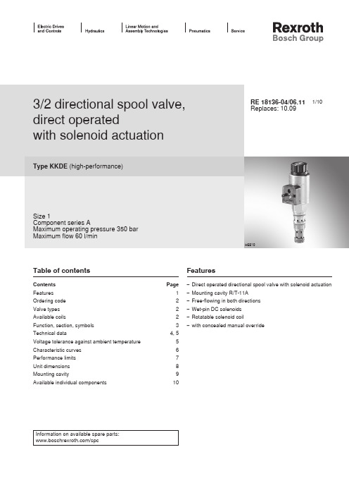
1/103/2 directional spool valve, direct operatedwith solenoid actuationType KKDE (high-performance)Size 1Component series AMaximum operating pressure 350 bar Maximum flow 60 l/minRE 18136-04/06.11Replaces: 10.09Table of contentsContents PageFeatures 1Ordering code 2Valve types 2Available coils2Function, section, symbols 3Technical data4, 5Voltage tolerance against ambient temperature 5Characteristic curves 6Performance limits 7Unit dimensions 8Mounting cavity9Available individual components10Features– Direct operated directional spool valve with solenoid actuation – Mounting cavity R/T-11A – Free-flowing in both directions – Wet-pin DC solenoids – Rotatable solenoid coil – with concealed manual overrideH6810Information on available spare parts:/spcOrdering code (valve without coil) 1)Spool symbolwithout manual override "N0"with concealed manual override "N9"Type Material no.Type Material no.C KKDER1CA/HN0V R901070094KKDER1CA/HN9V R901070103UKKDER1UA/HN0VR901070099KKDER1UA/HN9VR901070105Available coils (separate order) 1)Direct voltage DC 4)Material no. for coil with connector 3)"K4"03pol (2+PE)DIN EN 175301-803"K40"02pol K40DT 04-2PA, make Deutsch"C4"02pol C4/Z30AMP Junior Timer 12 V R900991678R900729189R90031581824 VR900991121R900729190R9003158191) Complete valves with mounted coil upon request 2) With transition function during the switching process 3) Mating connectors, separate order, see data sheet 08006Valve types (without coil) 1)4) Other voltages upon request5) Screwable manual override "N10" possible(Material no. R901051231, separate order)71Function, section, symbolsGeneralThe 3/2 directional spool valves are direct operated, pres-sure-compensated cartridge valves. They control the start,stop and direction of a flow and basically comprise a hous-ing (1) with a movably mounted socket (2), the controlspool (5)and a return spring (4).FunctionIn the de-energized condition, the control spool (5) is heldin the initial position by the return spring (4). The controlspool (5) is actuated by wet-pin DC solenoids (3). The sym-bols are realized by different spools (C or U). The mainports ①, ②, and ③ are suitable for a continuous load with anoperating pressure of 350 bar and the flow can be directedinto both directions (see symbols).The manual override (6) allows for the switching of the valvewithout solenoid energization. It is also available in screwableversion "N10" (7) (see page 2).Version "K4"(with mating connector)Version "C4"Symbol "C"Symbol "U"Type KKDER1CA/HN9VTechnical data (For applications outside these parameters, please consult us!)hydraulicMaximum operating pressure bar 350 (at all ports)Maximum flow l/min 60Hydraulic fluidSee table below Hydraulic fluid temperature range °C –40 to +80Viscosity rangemm 2/s 4 to 500Maximum permitted degree of contamination of the hydraulic fluid - cleanliness class according to ISO 4406 (c)Class 20/18/15 1)Load cycles 10 million (at 350 bar )generalWeight– Valve kg 0.3– Coilkg 0.25Installation position Any Ambient temperature range°C –40 to +1101) The cleanliness classes specified for the components mustbe adhered to in hydraulic systems. Effective filtration pre-vents faults and at the same time increases the service life of the components.For the selection of the filters see /filter.1201101009080706050-30-1001030507090110-20204060801001201101009080706050Technical data (For applications outside these parameters, please consult us!)electricVoltage type Direct voltage Supply voltage 2)V 12 DC; 24 DCVoltage tolerance against ambient temperature See characteristic curve below Power consumption W 22Duty cycle%See characteristic curve below Maximum coil temperature 3)°C 150Switching time according to ISO 6403(solenoid horizontal)– ON ms ≤ 80– OFF ms ≤ 50Maximum switching frequency cy/h 15000Protection class according to VDE 0470-1(DIN EN 60529)DIN 40050-9– Version "K4"IP 65 with mating connector mounted and locked – Version "C4"IP 66 with mating connector mounted and lockedIP 69K with Rexroth mating connector (Material no. R901022127)– Version "K40"IP 69K with mating connector mounted and locked2) Other voltages upon request3) Due to the surface temperatures of the solenoid coils, thestandards ISO 13732-1 and EN 982 need to be adhered to!At the electrical connection "K4", the protective earth-ing conductor (PE ) has to be connected properly.Voltage tolerance against ambient temperature; duty cycleA d m i s s i b l e s u p p l y v o l t a g e o f t h e n o m i n a l v o l t a g e i n % →Ambient temperature in °C →D u t y c y c l e i n % →1Maximum voltage 2Duty cycle3Minimum response voltage Admissible supply voltage rangeVoltage range and duty cycle depending on the ambient temperature5101520253001020304050215101520253035010203040506012Characteristic curves (measured with HLP46, ϑoil = 40 °C ± 5 °C and 24 V coil)Flow in l/min →P r e s s u r e d i f f e r e n t i a l i n b a r →∆p -q V characteristic curves – symbol C1① → ②② → ①2③ → ②② → ③1① → ②② → ①2③ → ②② → ③Flow in l/min →P r e s s u r e d i f f e r e n t i a l i n b a r →∆p -q V characteristic curves – symbol U123405010015020025030035040001020304050607012340501001502002503003504000102030405060Performance limits (measured with HLP46, ϑoil = 40 °C ± 5 °C and 24 V coil)Flow in l/min →O p e r a t i n g p r e s s u r e i n b a r →1① → ②2② → ③3③ → ②4② → ①1① → ②2② → ③3③ → ②4② → ①Symbol CFlow in l/min →O p e r a t i n g p r e s s u r e i n b a r →Symbol UAttention!The performance limits were determined when the solenoids were at op-erating temperature and at 10 % undervoltage.Unit dimensions (dimensions in mm)① = Main port 1② = Main port 2③ = Main port 3LS = Location shoulder12345Dimension () for "K4" mating connector, with circuitry 6Version "K40"7Version "C4"8Nut, tightening torque M A = 5+1 Nm 9Coil (separate order, see page 2)10Concealed manual override "N9", optional 11Screwable manual override "N10"(separate order, see page 2)Rz 321)Mounting cavity R/T-11A; 3 main ports; thread M20 x 1.5 (dimensions in mm)1) Differing from T-11A2) All seal ring insertion faces are rounded and free of burrs3) With counterbore4) Depth for moving parts① = Main port 1② = Main port 2③ = Main port 3LS = Location shoulderTolerance for all angles±0.5°Bosch Rexroth AG HydraulicsZum Eisengießer 197816 Lohr am Main, Germany Phone +49 (0) 93 52 / 18-0***************************** www.boschrexroth.de © This document, as well as the data, specifications and other informa-tion set forth in it, are the exclusive property of Bosch Rexroth AG. It may not be reproduced or given to third parties without its consent.The data specified above only serve to describe the product. No state-ments concerning a certain condition or suitability for a certain applica-tion can be derived from our information. The information given does not release the user from the obligation of own judgment and verification. It must be remembered that our products are subject to a natural process of wear and aging.Available individual components920910999Item Denomination Material no.910Nut R900991453920O-ring for pole tube R900007769999Seal kit of the valve R961003235A Manual override "N10" 1)R901051231ACoils, separate order, see page 21) Only with ordering code "N9", see page 2Bosch Rexroth AG HydraulicsZum Eisengießer 197816 Lohr am Main, Germany Phone +49 (0) 93 52 / 18-0***************************** www.boschrexroth.de © This document, as well as the data, specifications and other informa-tion set forth in it, are the exclusive property of Bosch Rexroth AG. It may not be reproduced or given to third parties without its consent.The data specified above only serve to describe the product. No state-ments concerning a certain condition or suitability for a certain applica-tion can be derived from our information. The information given does not release the user from the obligation of own judgment and verification. It must be remembered that our products are subject to a natural process of wear and aging.NotesBosch Rexroth AG HydraulicsZum Eisengießer 197816 Lohr am Main, Germany Phone +49 (0) 93 52 / 18-0***************************** www.boschrexroth.de © This document, as well as the data, specifications and other informa-tion set forth in it, are the exclusive property of Bosch Rexroth AG. It may not be reproduced or given to third parties without its consent.The data specified above only serve to describe the product. No state-ments concerning a certain condition or suitability for a certain applica-tion can be derived from our information. The information given does not release the user from the obligation of own judgment and verification. It must be remembered that our products are subject to a natural process of wear and aging.Notes。
- 1、下载文档前请自行甄别文档内容的完整性,平台不提供额外的编辑、内容补充、找答案等附加服务。
- 2、"仅部分预览"的文档,不可在线预览部分如存在完整性等问题,可反馈申请退款(可完整预览的文档不适用该条件!)。
- 3、如文档侵犯您的权益,请联系客服反馈,我们会尽快为您处理(人工客服工作时间:9:00-18:30)。
金科德说明书
Document serial number【UU89WT-UU98YT-UU8CB-UUUT-UUT108】
为一台饮水机设置周一到周五早8点到11点和周一到周五下午13点到17点的2个时间段开启步骤:
★、校对现在的时刻,同时按下“时钟”和“小时”即可调整时钟的小时显示,按一次增加一小时,长按可快速调整,采用同样的方法,可以设置当前的星期,分钟。
★、首先连续按“模式”键,将工作模式由“关”切换到“自动”模式(显示屏下部显示自动字样)。
★、设定第一时间段的开与关(20组中的一组)
A、按“设定”键,液晶显示时间段“1”、“开”字样(第一组开的时间)
B、调整定时开的分钟,按“分钟”键,设定分钟为00
C、调整定时开的小时,按“小时”键,设定小时为8
D、调整定时开的星期,连续按“星期”键,直到液晶屏显示星期模式为:星期一,星期二,星期三,星期四,星期五。
E、再按“设定”键,液晶显示时间段“1”、“关”字样(第一组关的时间
F、调整定时关的分钟,按“分钟”键,设定分钟为00
G、调整定时关的小时,按“小时”键,设定小时为11
H、调整定时关的星期,连续按“星期”键,直到液晶屏显示星期模式为:星期一,星期二,星期三,星期四,星期五。
★、按照类似方法可完成第二个时间段定时开与关的设定。
★、将定时器插入电源插座,注意此时通电灯应处于熄灭状态,否则请将控制模式先调整为“关”,再将“模式”切换到“自动关”(注:现
在时间在设置时段内放到“自动开”;现在时间在设置时段外放到“自动关”)
这样就设置完成了,请将饮水机的插头插到定时器的万能输出插座就可以了.
1)出门.出差或旅游定时热水器
经常出差或偶尔出门,这时一回到家就想洗热水澡,如果一直开着热水器会不停地加热,即不安全而且又费电,这时幸好有了微电脑定时开关,想让它几点加热都能办到,可以按照你的要求去实现.
2)定时煮饭
出门逛街,8:30回家,精疲力尽,真不想开锅做饭,可是,饭还得吃......矛盾怎么解决?微电脑定时开关解决方案:出门前淘好米,洗好菜,定好18:00时开始通电煮饭,回到家便有饭吃。
假如你今天上班前想要家里的紫砂电炖锅(慢炖锅)在您下班回到家前2小时开始炖汤,操作如下(假设回到家的时间是19:00点):
1.校对现在的时间,同时按下“时钟”和“小时”键调小时,同时按下“时钟”和“分钟”键调分钟,同时按“时钟”和“星期”调星期(若设置好的程序需长期使用,则在“设定”状态下按“星期”选择星期组合);
2.按“模式”键,将“模式”设置为“自动、关”;
3.按“设定”键,显示屏显示“1开”(开字在1字的右上角),按“小时”键,每按一次升1小时,调到17:00;再按一次“设定”键,模式显示为“1关”(关字在1字的右下角),这个关的时间,您可以根据您
所炖汤需时而定,现在假设需炖2.5小时,按“小时”键,调到“19:00”,再按“分钟”键,将时间调到“19:30”,OK,现在已经调好了,当您下班回到家时,一锅美味靓汤已经就快炖好了(当然,您可以设定开始时间提前半小时,您回到家时汤刚好炖好了)。
3)定时抽水
高层住宅,水压不够要装家庭抽水机的,可以定好每天的抽水时间如6:00-8:30,11:30-14:00,18:00-22:00,自动开关抽水机,其他时间不抽。
也可以设定周一-五是这样的循环,周六日是另外的循环。
家庭小假山的抽水,总不好每天24小时抽,定好时间在家时让抽水机工作。
还有鱼缸换水也是这样。
4)定时开关电热毯
特别是家里老人使用电热毯,经常开着就忘了关,真让人提心吊胆。
使用定时开关定好时间,每天睡前10分钟接通电源加热,一段时间后断电,全自动。
5)定时开关热水机
众所周知,饮用水加热六小时以上会产生亚硝酸盐,可致癌、产生血管等疾病。
定时开关是最好的解决方案。
6)办公室电源开关
经常忘了下班断开总闸,给办公室安全带来隐患。
定时开关可以定周一至周五早8:30开电源,晚18:00关电源,周六日关电源。
也可以很方便的随时手动开关电源。
科德数字式定时器”有三种模式,你可以让它常开,让它常关,让它为你控制你家的电,总有一种模式适合你。
“科德数字式定时器”能够在1天内预设高达8组的定时设置(16次开与关),任何时段都可以控制,并且每星期可设置十种星期组合,如下:
1)七天中只设其中的任意一天起作用,
2)七天中每一天都
上一页7/10下一起作用,
3)七天中只一、二、三、四、五起作用,
4)七天中只六、日起作用,
5)七天中只一、二、三、四、五、六起作用,
6)七天中只一、三、五起作用,
7)七天中只二、四、六起作用,
8)七天中只一、三、五、日起作用
注意:说明书所介绍的内容与实物有小小不同(产品有改进),若看说明书看不懂各状态所表示的含义的,请参照下面说明:
在时钟状态下,连续按“模式”键,液晶屏的左边将循环显示
“开”“自动”“关”等状态,说明如下:
关:液晶屏左边显示“关”时,表示定时器处于关闭状态,无输出;开:液晶屏左边显示“开”时,表示定时器处于恒通状态,所设置的开、关程序不起作用;
自动、关:同时显示这两种状态,表示定时器将按照您所设定的程序工作,此时处于关闭状态(即是无电源输出);
自动、开:同时显示这两种状态,表示定时器将按照您所设定的程序工作,此时处于打开状态(即是有电源输出);
特别说明“自动、关”和“自动、开”状态的区别:
正常工作时,“自动、关”和“自动、开”状态是自动跳转的,如果此时定时器处于关闭状态(自动、关),到了设定的打开时间时,会自动跳转为“自动、开”,同理,到了下一次时间时,又会自动跳转为“自动、关”;如果您调试好定时器后希望定时器立即工作(指处于打开状态),模式应该调为“自动、开”,如果您设置的开的时间是在将来的某一时间(现在不需要输出电源),则状态应该设置为“自动、关”。
产品应用
1.在实行峰谷电价差的地区,可使大功能率电器在低电价时段自动运行.
2.用于控制需定时开与关的家用电器,如:饮水机,热水器,空调,电饭煲,广告照明等.
3.用于控制通电时间长短.如:电瓶车、手机电池、蓄电池的充电等等.
4需频繁通断的用电场合.如花圊,草坪的间歇喷灌,鱼缸的周期性增氧过滤,喷泉等.
5.家庭防盗系统的自动控制.
科德微电脑定时插座性能介绍:
1.每天不同时段可以设定8开8关或者每个星期不同时段进行最多可达8次的开和关
2.最小控制开/关时间间隔:1分钟
3.可以长通或者长关
4.可以手动开关
5.有记忆性,断电1个月以上也能保留时间设置。
不象普通定时插座一遇到关闭断电或停电后所有时间设置需重新设定──麻烦。
6.多达16种循环模式:
a.每周一
b.每周二
c.每周三
d.每周四
e.每周五
f.每周六
g.每周日
h.每天
i.每周一、二、三、四、五
j.每周六、日
k.每周一、二、三、四、五、六
l.每周一、三、五
m.每周二、四、六
n.每周一、二、三
o.每周四、五、六
p.每周一、三、五、日断电或停电后所有时间设置需重新设定──麻烦。
6.多达16种循环模式:
a.每周一
b.每周二
c.每周三
d.每周四
e.每周五
f.每周六
g.每周日。