TC-225天车说明书
zj40j钻机技术参数
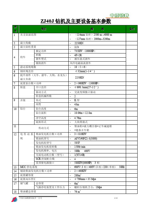
辅助刹车
风冷电磁涡流刹车
5 游动系统绳数
- 10(5³6)
6 钢丝绳直径
¢32mm(1-1/4″)
6 提升部件(天车、游车、大钩、水龙头) 最大负荷
2250KN
7 泥浆泵台数³功率
8 转盘
开口直径
- 2³960KW(1300HP) - ¢698.5mm(27-1/2″)
9 井架
驱动方式 转盘机械档数 形式 高度
- 重量:1480kg
- 生产厂家:兰石化工机器总厂
7.3 ¢500 惯 性刹车装 - 离合器型号:LT800/125
置
- 极限扭矩:810 公斤
- 工作压力:7-9kg/cm2
- 外形尺寸:720³154³800mm
- 重量:41.2kg
- 生产厂家:兰石化工机器总厂
8
绞车
-
8.1 绞车主参数
- 型号:JC-40
1台
- 最大钩载:2250KN
- 主钩直径:¢160mm
- 付钩直径:¢100mm
- 弹簧工作行程:180mm
- 弹簧负荷:
-
工作形成开始时:27.15kN
-
工作行程中止时:53.56kN
- 主钩口开品尺寸:190mm
- 钩身旋转半径:420 mm
- 外形尺寸(长³宽³高):2545³720³750mm
-
冬季 L-HV32 低温抗磨液压油
-
单泵额定流量:18L/min
-
油箱容积:80L
-
电机功率:2.2KW
-
蓄能器容量:4³6.3L
-
加热器功率:1KW
-
冷却水流量:2m3/h
-
外形尺寸:1160³960³1220
吸料天车使用手册说明书

尊敬的顾客:欢迎您使用我公司的产品桥式吸料天车。
本机是炭素填充料抽吸的专用操作设备,又是集机械、气动、环保、电气、自动控制为一体的高新技术产品。
您在使用、维修前必须阅读该说明书,遵循说明书中的要求进行操作。
违反说明书操作要求,会危害设备、造成人身安全事故。
欢迎您提出宝贵意见,以利于持续改进。
1、机组的概述1、1机组的用途及使用范围1、1、1机组的主要用途炭素填充料抽吸专用设备,它能完成下列工艺操作:●●●用填料管将填充料加入炉坑●用气力输送设备的吸料管将高温填充料从炉坑中吸出,并进行粉尘分级作业。
●●用10助吊钩搬运车间内的其它设备(燃烧架、吸风管、热电偶架、排烟架、烟气测量架、冷却架等)及其它零星吊运。
●1、1、2使用范围适合于大量炭粉尘、碳氢化合物、烟气和二氧化硫,最高环境温度55℃。
1、2机组的组成炭素焙烧多功能机组主要由几大部分组成:●大车是焙烧多功能机组的桥架,可沿车间的纵向轨道运行,并配置有吨电葫芦用来承担专门的吊运任务。
●小车是焙烧多功能机组的核心,焙烧多功能机组的主要作业工具、操纵室及电气控制系统均配置其上,小车可沿大车主梁顶面的轨道横向运行。
●电气控制系统采用PLC可编程序控制,在操纵室内的联动台上集中操纵。
联动台上集中操纵。
联动台上配置触摸屏,触摸并上可实现各电气元件的使用状态。
显示故障部位及原因并报警,可采用无线信号交换装置对地面设备进行控制。
2、机组的工作条件、工作环境2、1工作环境●环境空气:环境空气中含有碳粉、碳氢化合物、烟气和二氧化硫等有害物质。
●环境温度:在最高温度55℃环境工作。
2、2工作条件2、2、1供电条件●交流380V/220 V±10%三相(三相四线制)●频率50HZ±1%2、3工作制度整个机组每天工作三班,每班八小时连续运行,每周维护时间不少于10小时。
3、机组的主要规格及技术参数3、1机组的总体参数:●机组跨度:m●工作级别:●吸卸料能力:m3/h●电机组机总功率:KW●大车轨道型号:3、2大车●工作级别●运行减速器型号:●运行速度:m/min●调速方式:变频调速3、3小车●工作级别●运行减速器型号:7.5KW×2●运行速度:m/min●调速方式:变频调速3、4吸卸料装置●提升减速机型号:●提升电机功率:KW ●提升速度:m/min ●吸卸料升降行程:mm●起重能力:kg﹡23、5罗茨真空泵●罗茨真空泵型号:●配套电机型号:●进口流量:m3/ min●真空度:—35Kpa3、6旋风除尘器●型号:HA173-S2●处理物料:锻后石油焦粉尘气体●处理气量:173 m3/min3、7空气冷却器●型号:HA173-S1●处理物料:锻后石油焦粉尘气体●进气温度:≤320℃●出气温度:≤90℃●冷却面积:m2●轴流风机型号:型台配用电机型号:功率:Kw﹡43、8脉冲式布袋除尘器及其反吹控制系统●型号:●处理物料:石油焦粉尘气体●处理气量:m3/h处理前气体含尘量:处理后气体含尘量:30-60 g/ m3●滤袋材质:针刺过滤毡●滤袋耐温:工作温度240℃●清灰振动电机:2×1.5kw●过滤面积:m23、9电葫芦●型号:●运行速度:m/min●起升重量:t●起升速度:m/min●起升行程:m3、10空调器●型号:●冷却功率:2000 w制冷剂:R134a●电压/启动电流:400V/7.5A●外形尺寸:595﹡475﹡415●重量:48 Kg4、机组的主要结构、特性及工作原理4、1大车大车为双梁桥架结构,由两根平行的大梁通过高强螺栓固定在两个端梁上,每个端梁是由两个小端梁通过联杆铰接而成。
T225RS 用户手册说明书

Engine Safety PrecautionsIMPORTANT SAFETY INFORMATIONMost accidents with engines can be prevented if you follow all instructions in this manual. Some of the most common hazards are discussed below, along with the best way to protect yourself and others.OWNER RESPONSIBILITIES• The engines are designed to give safe and dependable service if operated according to instructions. Read and understand this owner’s manual before operating the engine. Failure to do so could result in personal injury or equipment damage. • Know how to stop the engine and understand the operation of all controls. • Never permit anyone to operate the engine without proper instructions. • Keep children and pets far away from the area of operation. • Never modify or change the engine in any way.Table of ContentsEngine Safety Precautions 1Product Specification2Recommended Torque Values 2 Recommended Maintenance and Tips 2Assembly Guidelines 3Starting the Engine3 Engine Break-in Procedure 3Safety References4For Warranty Matters, contact your local dealeror ******************RE-FUEL WITH CAREPetrol is extremely flammable, and gasoline vapor can explode. Refuel outdoors in a well-ventilated area with the engine stopped. Never smoke near fuel and keep other flames and sparks away. Always store petrol in an approved container. If any fuel is spilled, make sure the area is dry before starting the engine.HOT EXHAUST• The muffler becomes very hot during operation and remains hot for a while after stopping the engine. Be careful not to touch the exhaust at this time. It is highly recommended to fit the heat shieldwrap to as protection from the hot exhaust manifold.• To prevent fire hazards and to provide adequateventilation for stationary equipment applications, keep the engine at least 1metre away from building walls and other equipment during operation. Do not place flammable objects close to the engine.CARBON MONOXIDE HAZARDExhaust gas contains poisonous carbon monoxide. Avoid inhalation of exhaust gas. Never run the engine in a closed garage or confined area.R e c o m m e n d e d T o r q u e V a l u e sP r o d u c t R e c o m m e n d a t i o n sP r o d u c t S p e c i f i c a t i onNote: Check the Tillotson Racing Youtube Page for Video Link to ‘T225RS Engine Maintenance’: https://youtu.be/Fc36XblpR4kAssembly Guidelines• Assemble the auxiliary engine components – Intake Manifold, FM22-1A Carburettor, Air Filter, Exhaust, Clutch, Clutch guard • It is recommended that the exhaust heat wrap is mounted to the exhaust manifold to protect from heat build-up • Ensure the Fuel Pump connections are correct as per photo:• Mount the 45cm Fuel Pipe supplied from the fuel pump outlet to the carburettor inlet connector • Fill the engine withT4 Engine Oil 500ml (17oz)*Note: Black Fuel Line represents the Pulse Connection from the fuel pump to the intake manifold connector.Note: For a Video Link showing all of the above steps mentioned please visit the Tillotson Racing Youtube Page: https:///channel/UCZgldHZl8EBj93WnvcKFRHAInstallation to ChassisWhen mounting to a Tillotson T4 chassis, using the supplied engine mount and no chassis modifications are needed. However, with other chassis brands there may be a need for an alternative sliding engine mount, which will allow for the engine to be offset giving more space for the chain & chain guard.Starting the EngineWhen starting the engine from new or when empty of fuel1. It is necessary to blow the fuel to fill the carb bowl from the overflow pipe on the tank. Make sure to blow for no less than 15seconds as the bowl requires a large volume of fuel before the engine will start.2. Lift the Choke to the raised position which means the choke is now ‘ON’ and ensure the engine ignition switch is in the ‘ON’ position also.3. Using some small throttle opening (10-30%) pull the starter chord until the engine fires and reset the Choke so it is in the ‘Off’ position.4. Once the engine is running it may be necessary to adjust the idle speed screw on the side of the carburetor. Recommended engine idle is 1,800 - 2,000rpm.Engine Break-in ProcedureNote: DO NOT REV THE ENGINE HARD WITH NO LOAD FROM NEW.1. Insert 500ml of T4 Oil (17oz).2. For the first 10 minutes, drive moderately at varying speeds up to 5,000rpm (half throttle). It is important to vary the RPM for proper camshaft, piston rings and moving component bed in.3. Stop and allow the engine to cool, check that there are no fuel or oil leaks.4. For the second 10 minutes, build up to max 6,500rpm by the end of the session.5. Once you have completed the running-in procedure it is recommended to change the oil. This is to remove any metal particles which could arrive from the new components in the engine. Drain the oil when hot so it can easily transport any particles.6. After the engine is empty, replace the drain plug (make sure the aluminium washer is still there) and re-fill the engine with 500ml of fresh oil. The engine is now ready for competition.*VERY IMPORTANT: If the engine is run on less oil than recommended it will overheat the engine componentsand performance / reliability will be reduced for the remainder of the engine life.SAFETY REFERENCESThe safety alert symbol is used to identify safety information about hazards that can result in personal injury. A signal word (DANGER, WARNING, or CAUTION) is used with the alert symbol to indicate the likelihood and the potential severity of injury. In addition, a hazard symbol may be used to represent the type of hazard.This manual contains safety information to make you aware of the hazards and risks associated with engines, and how to avoid them. Because we do not necessarily know what equipment this engine will power, it is important that you read and understand these instructions and the instructions for the equipment this engine powers.SYMBOLS ASSOCIATED WITH THIS ENGINEFire Read Manual Kickback Fuel Toxic Fumes Hazardous ChemicalsShock Stop Explosion Oil Hot Surface Fuel ShutoffMoving Parts Choke SlowFast。
TC-225天车架结构强度的有限元分析
基 本方 法_ ] 1 ,是一 种 简单 有 效 的 判 定结 构 安 全 性 的 准则 。该准则 中关 于结 构许 用 安全 系数 值 的选 择 ,是
全 面 考 虑 载 荷 特 征 、材 料 特 性 、 制 造 环 境 因 素 以 及 该
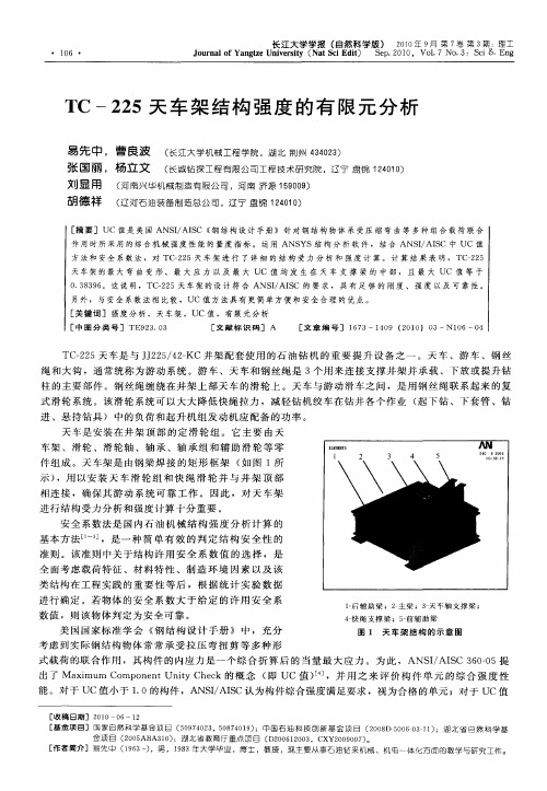
车架 、滑轮 、滑轮 轴 、轴 承 、轴承 组 和 辅助 滑 轮 等零 件 组成 。天车 架是 由钢梁 焊 接 的矩 形 框架 ( 图 1所 如 示) ,用 以安 装 天 车 滑轮 组 和 快 绳 滑 轮 并 与 井 架 顶 部 相连 接 ,确保其 游 动 系统 可靠 工 作 。 因此 ,对 天 车架 进行结 构受 力分 析和强 度计 算十 分重要 。
式滑 轮系统 。该 滑轮 系统 可以大 大降低 快绳 拉力 ,减 轻钻机 绞 车在钻 井各 个作 业 ( 下 钻 、下 套管 、钻 起
进 、悬 持钻 具) 中的负 荷和起 升机 组发 动机应 配备 的 功率 。
天 车 是 安 装 在 井 架 顶 部 的 定 滑 轮 组 。 它 主 要 由 天
能 。对 于 UC值小于 10的构件 ,A IA S . NS/ IC认为构件综 合强度满 足要求 ,视 为合 格 的单元 ;对 于 UC值
[ 收稿 日期 ] 2 1 0 0 0— 6—1 2 [ 基金 项 目] 国 家 自 然 科学 基 金 项 目 ( 0 7 0 3 0 7 0 9 ;中 国 石 油 科 技 创 新 基 金 项 目 ( 0 8 ̄50 —31 ) 5 9 4 2 ,5 8 4 1 ) 20 I 0 60 1 ;湖 北 省 自 然 科 学 基 金 项 目 ( 0 5 A3 0 ;湖 北 省教 育 厅 重 点 项 目 ( 2 0 1 0 3 2 0 AB 1 ) D 0 6 2 0 ,C 2 0 0 7 。 XY 0 9 0 ) [ 者 简 介 ] 易 先中 ( 9 3一 ,男 , 18 作 16 ) 9 3年大 学毕 业 ,博 士 ,教 授 ,现 主 要 从 事石 油钻 采机 械 、机 电 一 体 化 方 面 的 教 学 与研 究 工 作
天车使用说明书

20/5t交流桥式起重机使用说明书机床电气系统一、概述20/5t交流桥式模拟起重机是湖南铁道职业技术学院实训中心为了满足中级、高级维修电工实训和中、高级维修电工等级证考试,而自行设计和安装调试的一台教学用设备。
该模拟起重机除了机械部分外,其电气设施部分与实际的20/5t交流桥式起重机相比,具有完全相同的电气控制系统,同时具有电气线路标准化、操作灵活、使用安全、维修方便教学直观等特点。
二、电气组成部分20/5t交流桥式起重模拟机有5台YR7114A型绕线式异步电动机(副钩电机M1、小车电机M2、大车电机M3与M4共同拖动、主钩电机M5),同时有PXQY1-150控制屏柜和3台ITJ15/32-1型凸轮控制器以及1台LK10-10/1212型主令控制器等进行拖动控制。
电机过载保护由XQB-150-2型保护屏柜中的KI1~KI5过电流继电器实现过载和过流保护,KI0为总过流保护。
YA1~YA5分别为副钩、小车、大车、主钩的制动电磁铁。
SQ1、SQ2为小车前后限位开关,SQ3、SQ4为大车左右限位开关,SQa 、SQb为主、副钩超高限位开关, SQc为楼梯安全开关,SQe 为天桥门安全开关,SQd为司机室门安全开关,SA为紧急停止开关。
三、电路工作原理(一)副钩、小车、大车电路副钩、小车、大车电路的控制原理基本相同,只是大车的拖动是由2台电机拖动。
现以大车为例分别介绍电动机的主电路、控制电路及其安全、联锁保护电路。
1、大车电路工作准备合上电源开关QF1线路通入电源,合上紧急开关SA,在所有凸轮控制器及主令控制器均在“0”位,司机室门、楼梯门、天桥门均关好,相应的安全开关SQc 、SQe、SQd均闭合,所有的过电流继电器均未动作的情况下,按下启动按钮SB,接触器KM线圈得电吸合,并通过联锁触点SA3—5与SQ4或SA3—6与SQ3组成自锁电路。
若限位开关被压切断自锁电路, KM 失电使电动机停止转动,此时应使大车向相反的方向运动,则必须先将大车凸轮控制器SA3手柄回到“0”位,才能使KM线圈重新通电吸合。
天车.游车.大钩.转盘

天车、游车、大钩、水龙头、转盘培训讲义2006年10月前言天车、游车、大钩、和转盘是钻机的重要部件。
为了使油田有关操作人员熟悉和掌握它们的使用维护方法,本讲义分别对它们作了介绍。
在使用时所需的关于配套设备(或部件的)结构参数和使用维护等项内容以及相关的资料,详见配套设备的使用说明书和其他有关的技术文件。
在使用这些设备以前,参与此项工作的管理人员、技术人员和操作者必须仔细阅读使用维护说明书及与这些设备有关的说明书和相关资料,了解并熟悉所有的细节,此外还要具备相应的安全操作知识和技能。
全部的管理工作和具体操作还应按照本系统、本单位相关的规章制度要求执行。
限于编者的水平和能力,讲义中可能会出现缺点和错误,恳切希望各位提出批评和建议。
目录第一章天车、游车和大钩概述 (1)第二章天车 (3)一、天车的类型和结构 (3)二、天车的维护与保养 (5)三、南堡项目天车介绍 (6)第三章游动滑车 (8)一、游车的类型和结构 (8)二、游车的维护与保养 (9)三、南堡项目游车介绍 (10)第四章天车和游车在使用、运输及贮存中应注意的问题 (12)第五章钻井大钩 (12)一、钻井大钩的类型和结构 (12)二、钻井大钩的维护与保养 (14)三、南堡项目钻井大钩介绍 (15)四、大钩使用、运输和贮存中应注意的问题 (17)五、组和式游车大钩介绍 (19)第六章转盘 (20)一、典型转盘的结构 (20)二、转盘的安装与使用 (22)三、转盘的维护与保养 (24)四、南堡项目转盘介绍 (26)五、运输与贮存 (28)第七章水龙头 (29)一、水龙头的类型和结构 (29)二、水龙头的维护与保养 (32)三、水龙头常见故障及处理方法 (34)第一章天车、游车和大钩概述钻机的起升系统担负着起下钻具、下套管以及控制钻头送进等工作,以辅助完成钻井生产。
为完成这些工作,可以采用不同的起升系统:机械滑车组、液压方式、杠杆或齿轮方式等,但到目前为止,机械滑车组是最广泛使用的方式。
天车起重量限制器说明书

OCS-CY标准型起重量限制器(T321) 使用说明书本手册版权归梅特勒-托利多(常州)称重设备系统有限公司所有,未经许可不得翻印、修改或引用!METTLER TOLEDO为梅特勒-托利多公司的注册商标!METTLER TOLEDO保留修改本说明书的权利目录1 使用须知 (3)2 安全操作提示 (3)3 主要技术参数 (4)3.1 产品规格的标注 (4)3.2 主要技术参数 (4)4 部件指南 (5)4.1系统构成示意图 (5)4.2传感器(含轴承座)的外形及安装尺寸 (6)5 CraneMate T321仪表 (7)5.1T321仪表概述 (7)5.2T321仪表主要技术参数 (7)5.3T321仪表主要功能 (7)5.4安装注意 (7)5.5电气接线 (8)5.5.1 电源线连接 (8)5.5.2 系统接线图 (8)6 系统安装 (9)6.1开箱检查 (9)6.2电源准备 (9)6.3安装步骤 (9)7 T321日常使用 (10)7.1T321仪表上电 (10)7.2 T321仪表显示 (10)7.3T321仪表键盘 (10)7.4T321仪表操作 (11)7.4.1 设置报警点 (12)7.4.2 设置起重机限制器的最大容量 (12)7.4.3 设置分度值 (13)7.4.4 标定 (13)7.4.5 线性标定 (14)7.4.6 错误代码 (15)8 维护和保养 (16)8.1 常用维修工具 (16)8.2日常清洁和维护 (16)1 使用须知起重量限制器,是在起重机起吊运输货物的过程中对起重机进行超载保护的装置。
梅特勒-托利多的OCS-CY 系列起重量限制器可广泛应用于多种桥式\梁式起重机或其它结构相似的起重设备。
本产品根据GB6067-85《起重机械安全规程》及GB3811-83《起重机设计规范》的要求进行设计和生产。
依托梅特勒-托利多集团的全球设计与制造资源,各项指标均达到或优于GB12602-90《起重机械超载保护安全技术规范》中的相关规定。
CD225 吊车式吊车辆数据手册-英制说明书

CD225CAB DOWN CRANECD225DATASHEET -IMPERIALFeatures:Rated capacity:25 ton @10 ft working radius Maximum boom length: 72 ftMaximum tip height:121 ftCONTENTSCD225Page: Key. . . . . . . . . . . . . . . . . . . . . . . . . . . . . . . . . . . . . . . . . . . . . . . . . . . . . . . . . . . . . . . . . . . . . . . . . . . . . . . . . . . . . . . . . . . .3DimensionsCrane dimensions . . . . . . . . . . . . . . . . . . . . . . . . . . . . . . . . . . . . . . . . . . . . . . . . . . . . . . . . . . . . . . . . . . . . . . . . . .4 Crane weights . . . . . . . . . . . . . . . . . . . . . . . . . . . . . . . . . . . . . . . . . . . . . . . . . . . . . . . . . . . . . . . . . . . . . . . . . . . . . .5Load ChartsRange Diagram – Main Boom – Outriggers fully extended (100%) . . . . . . . . . . . . . . . . . . . . . . . . . . . . . .6 Load Chart – Main Boom – Outriggers fully extended (100%) . . . . . . . . . . . . . . . . . . . . . . . . . . . . . . . . . .7 Range Diagram – Main Boom – 26 ft offsettable jib . . . . . . . . . . . . . . . . . . . . . . . . . . . . . . . . . . . . . . . . . . .8 Load Chart – Main Boom – 26 ft offsettable jib . . . . . . . . . . . . . . . . . . . . . . . . . . . . . . . . . . . . . . . . . . . . . . .9 Range Diagram – Main Boom – 43 ft offsettable jib . . . . . . . . . . . . . . . . . . . . . . . . . . . . . . . . . . . . . . . . . . .10 Load Chart – Main Boom – 43 ft offsettable jib . . . . . . . . . . . . . . . . . . . . . . . . . . . . . . . . . . . . . . . . . . . . . . .11 Range Diagram – Main Boom – On tires . . . . . . . . . . . . . . . . . . . . . . . . . . . . . . . . . . . . . . . . . . . . . . . . . . . . . .12 Load Chart – Main Boom – On tires . . . . . . . . . . . . . . . . . . . . . . . . . . . . . . . . . . . . . . . . . . . . . . . . . . . . . . . . . .13Technical DescriptionBoom . . . . . . . . . . . . . . . . . . . . . . . . . . . . . . . . . . . . . . . . . . . . . . . . . . . . . . . . . . . . . . . . . . . . . . . . . . . . . . . . . . . . . .14 Hoist, rope and hook . . . . . . . . . . . . . . . . . . . . . . . . . . . . . . . . . . . . . . . . . . . . . . . . . . . . . . . . . . . . . . . . . . . . . . .14,15 Superstructure . . . . . . . . . . . . . . . . . . . . . . . . . . . . . . . . . . . . . . . . . . . . . . . . . . . . . . . . . . . . . . . . . . . . . . . . . . . . .15 Cab, controls, operator aids and load limiter/load indicator . . . . . . . . . . . . . . . . . . . . . . . . . . . . . . . . . .15,16 Carrier, engine, drive-line and hydraulic system . . . . . . . . . . . . . . . . . . . . . . . . . . . . . . . . . . . . . . . . . . . . . . .16 Vehicle performance . . . . . . . . . . . . . . . . . . . . . . . . . . . . . . . . . . . . . . . . . . . . . . . . . . . . . . . . . . . . . . . . . . . . . . . .17 Tires . . . . . . . . . . . . . . . . . . . . . . . . . . . . . . . . . . . . . . . . . . . . . . . . . . . . . . . . . . . . . . . . . . . . . . . . . . . . . . . . . . . . . . .172CD225 KEYCounterweightMain boomBoom lengthTip heightBoom with extensionMain boom with aux headSlewing / Allowable slewing range Slewing brakeOutriggers / Lifting on outriggers(100/50/0% extended)Main hoistHoist speedRope –Standard / OptionalRope diameterHook blockCabOperator aids / Load limiter / Load indicator Mechanical transmissionHydraulicsWorking temperatureLightsCrane / Crane in standard configuration Crane without counterweight General performanceTelescoping modeBoom luffing angleWorking radiusMax. boom length with extensionDistance from the hook to the head sheave pin Slewing locked / Slewing locked at specified position Slewing gearsLifting on wheels / Pick & CarryAuxiliary hoistRope lengthMax. line pullTireControlsEngineSteeringSpeedHeating / Air conditioningGradeabilityGross vehicle weightWeight on front axleWeight on rear axle3CRANE DIMENSIONSCD2254Note:14.00 x 2420.5 x 25Track width 6’.9.9’’6’-10.5’’Overall width8’-0’’8’-8’’Note:All heights are based on 20.5 x 25 tires. Use of 14.00 x 24 tires will reduce height by 2.5’’.CRANE WEIGHTSApproximate WeightsCD2255STD (without hoo block and auxiliary hoist)42,534 lb20,480 lb22,054 lb Add / Subtract for main optional equipment26 ft to 43 ft swing on jib stowed61 ft boom+1490 lb+ 1944 lb–454 lb72 ft boom+1490 lb+ 2489 lb–999 lbAuxiliary boom head61 ft boom+ 100 lb+ 257 lb–158 lb72 ft boom+ 100 lb+ 290 lb+ 191 lbAuxiliary hoist*+ 115 lb–25 lb+ 140 lb 25T, 2 sheave hook block+ 682 lb+ 1155 lb–473 lb 7T, hook and ball (in tool box)+ 240 lb+ 81 lb+ 159 lbNOTE: Values are subject to 2% variation * Weight includes ropeCD225with hook block:4 ft5 inRANGE DIAGRAM –MAIN BOOMOutriggers Fully Extended (100%)6CD225 LOAD CHART –MAIN BOOMOutriggers Fully Extended (100%)Standard ASMEB30.57CD225with hook block:4 ft5 inRANGE DIAGRAM –MAIN BOOMWith Jib, 26 ft offset89CD225LOAD CHART –MAIN BOOMWith Jib, 26 ft offset7,200 lbs14 ft 6 in(100%)360°Standard ASMEB30.5CD225with hook block:4 ft5 inRANGE DIAGRAM –MAIN BOOMWith Jib, 43 ft offset10CD225 LOAD CHART –MAIN BOOMWith Jib, 43 ft offset7,200 lbs14 ft 6 in (100%)360°Standard ASMEB30.511CD225with hook block:4 ft5 inRANGE DIAGRAM –MAIN BOOMOn Tires1213CD225Notes to lifting capacityLifting capacities do not exceed 85% of tipping load. Weight of hook blocks and slings is part of the load, and is to be deducted from the capacity ratings. Consult operation manual for further details.Note: Data published herein is intended as a guide only and shall not be construed to warrant applicability for lifting purposes.Crane operation is subject to the computer charts and operation manual both supplied with the crane.360°BoomStandard configuration:3 sections hydraulic actuated boomFull power mechanically synchronizedMin. / Max.30 ft / 72 ftBoom elevation angle range (min. / max.)-4° / 76°Optional configuration:One section jib26 ftOffset0, 15 and 30 degreesMaximum tip height103 ftTwo section jib26 ft to 43 ftOffset0, 15 and 30 degreesMaximum tip height121 ft Hoist, Rope and HookStandard configuration:Grooved drumStorage capacity570 ftTwo speed ratiosWithout load in 5th layer (low range / high range)227 ft/min / 364 ft/minWithout load in 1st layer (low range / high range)157 ft/min / 252 ft/min6 x 19 IWRC XIPS, right regular lay, preformed5/8 in455 ftMax. line pull; 1st layer low-range12,510 lbsMax. line pull permissible9,000 lbs14Optional configuration:Hook and ball239 lbs2 sheaves680 lbs3 sheaves660 lbs4 sheaves660 lbsGrooved drumStorage capacity570 ftWithout load in 5th layer (low range / high range)227 ft/min / 364 ft/minWithout load in 1st layer (low range / high range)157 ft/min / 252 ft/minRotation resistant compacted strand 18 x 19 or 19 x 195/8 in455 ftMinimum breaking strength 35,800 lbsMax. line pull permissible9,000 lbs SuperstructureStandard configuration:Non stop360ºMaximum rotation speed without load 3 rpmHydraulic motorPlanetary reducer360ºhouse lockManually actuated by foot pedalCab, Controls, Operator aids and Load limiter / Load indicatorStandard configuration:Rubber floor matTinted safety glassSix way adjustable seatArmrest mounted dual axis electro-proportional joysticksSteering wheel column with gear selector on the left and directional light selector on the rightDashboard mounted switches for outrigger operationGraphic interface for load indicator15Optional configuration:Hydraulic powered air conditionerHydraulic powered heaterWork lightsRotating beaconCarrier, Engine, Drive-line and Hydraulic systemStandard configuration:Hydraulic, independent extension:Diameter of outrigger pads24 inArea of outrigger pads452 in2Cummins QSB4.54 cylindersRated power130 hp @ 2,300 rpmMaximum gross torque459 ft·lb @ 1,500 rpmIntake: turbocharger with intercoolerFuel type DieselFuel tank capacity50 gallons6 x 6 powershift transmission with integral torque converterFull time 4WD (Four-Wheel Drive)Rigid mounted front axleOscillating rear axleDifferential lock on front axle and rear axleRear axle oscillation lock – manual or automatic actuationAir-over-hydraulic disc brakesParking brake on front axleHydraulic oil cooler on carrierHydraulic power steeringFront wheel steeringFour wheel steering concentricFour wheel steering crabOptional rear wheel steering packageHydraulic Pumps:Tandem pumps:Boom lift / T elescope30 gal/min @ 3,500 psiPower steering / Outriggers and Swing21 gal/min @ 2,500 psiSingle pump:Main and auxiliary hoist pump41 gal/min @ 3,500 psiHydraulic oil reservoir capacity94 gallonsHydraulic oil suction filter250 micronsHydraulic oil return filter 5 microns16Vehicle performanceStandard configuration:Max. in 1st gear (low range)112 %Max. in 3rd gear (high range) 3.8 %Max. (6th gear)24.5 mph TiresStandard configuration:Wide tread earth mover pattern (E3)20.5 x 25-20 PROptional configuration:Industrial pattern14.00 x 24-20 PR 17CD225Effective Date: October 2010.Product specifications and prices are subject to change without notice or obligation. The photographs and/or drawings in this document are for illustrativep urposes only. Refer to the appropriate Operator’s Manual for i nstructions on the p roper use of this equipment. F ailure to follow the a ppropriate Operator’sM anual when using our equipment or to otherwise act i rresponsibly may result in s erious injury or death. The only w arranty applicable to our equipment isthe standard written warranty a pplicable to the particular product and sale and T erex makes no other warranty, e xpress or i mplied. P roducts and services listed may be trademarks, service marks or trade-names of T erex C orporation and/or its s ubsidiaries in the USA and other countries. All rights are reserved.T erex®is a r egistered trademark of T erex Corporation in the USA and many other c ountries.Copyright 2010 T erex CorporationT erex Cranes, Global Marketing, Dinglerstraße 24, 66482 Zweibrücken, GermanyT el.+49(0)6332830,Email:*********************,Brochure Reference: TC-DS-I-E-CD225-10/10。
- 1、下载文档前请自行甄别文档内容的完整性,平台不提供额外的编辑、内容补充、找答案等附加服务。
- 2、"仅部分预览"的文档,不可在线预览部分如存在完整性等问题,可反馈申请退款(可完整预览的文档不适用该条件!)。
- 3、如文档侵犯您的权益,请联系客服反馈,我们会尽快为您处理(人工客服工作时间:9:00-18:30)。
TC-225天车
使用说明书
前言
TC-225天车的设计符合API SPEC 4F和API SPEC 8A规范。
为了使操作人员熟悉和掌握钻机天车的使用,本说明书介绍了天车的结构、技术参数、操作维护等。
在使用钻机天车以前,参与此项工作的管理人员、技术人员和操作者必须仔细阅读本说明书及与钻机天车有关的说明书和相关资料,了解并熟悉所有的细节,此外还应具备相应的安全操作知识和技能。
全部的管理工作和具体操作应按照本系统、本单位的相关的规章制度的要求执行。
1、概述
TC-225天车是钻机的重要配套部件。
天车安装在钻机井架上,用以和游动滑车、
绞车、大钩等一起完成起下钻和下套管作业。
1.1 天车简介
天车是安装在井架顶部的定滑轮组,与游车用钢丝绳联系组成一套滑轮系统,它
承受最大钩载和快绳、死绳的拉力,并把这些载荷传递到井架和底座上。
天车架采用
优质结构钢板焊接而成,其设计和天车主轴的设计均符合API 4F规范的要求, 天车
的主滑轮及轴承符合API 8A规范的要求。
1.2 主要技术参数
●型号 TC-225
●大钩钩载 225kN
●适用钢丝绳直径Φ3` mm
●滑轮外径Φ1120mm
●导向轮外径Φ1270mm
●主滑轮数 5个
●导向轮数 1个
●起重架最大载荷 20kN
●辅助滑轮外径Φ400mm
●辅助滑轮数 3个
●辅助滑轮适用的钢丝绳直径Φ19mm
●外形尺寸(长×宽×高) 3285mm×2596 mm×1960mm
●理论重量 5582kg
●配套井架型号 JJ225/43-K井架
2、结构说明
TC-225天车主要由天车架、主滑轮总成、导向轮总成、辅助滑轮总成、起重架、
防碰装置、及挡绳架、围栏等部件组成。
见明细表1、附图1
2.1 天车架
天车架采用整体焊接结构。
上部用螺栓分别与主滑轮轴座及导向滑轮轴座、捞砂轮总成连接,下部用M30的螺栓与井架相连。
2.2 主滑轮总成
主滑轮总成由主轴、支座、5个滑轮、轴承等组成。
每个滑轮内均装有一付轴承,轴端设有给每个滑轮加注润滑脂的M10×1黄油嘴,可方便地向轴承内加注润滑脂。
在滑轮外缘装有挡绳架,可防止钢丝绳从滑轮槽内脱出。
见明细表2 及附图2
2.3 导向滑轮总成
导向滑轮总成由轮轴、支座、滑轮、轴承等组成。
轴端装有一个M10×1黄油嘴,可方便地向轴承内加注润滑脂。
在滑轮外缘装有挡绳架,可防止钢丝绳脱出滑轮槽。
见明细表3及附图3
2.4 辅助滑轮总成
天车上装有3组辅助滑轮,滑轮轴端均装有M10×1黄油嘴。
辅助滑轮总成可分别用于两台气动绞车起吊重物、钻杆及悬吊液气大钳。
见明细表4及附图4
2.5 天车起重架
天车起重架供维修天车用,最大起重量为20kN。
见明细表5及附图5
2.6 防碰装置
天车梁下部装有防碰装置,可在游车冲撞天车时起到缓冲作用。
3、维修及保养
3.1 工作前的维护检查
为了使天车长期无故障工作,应及时正确的进行保养。
天车安装前如果有不正常的情况必须排除。
天车在工作前应进行以下检查:
1) 所有连接必须固定牢靠,不得有松动现象。
2) 各滑轮的转动应灵活,无阻滞现象。
当转动一个滑轮时,其相邻滑轮不应随着转动。
3) 各滑轮轴承应定期加注润滑脂,并检查润滑脂嘴和油道是否通畅。
各滑轮轴承每周加注ZL-3锂基润滑脂(SY1412-75)两次。
4) 各滑轮轴承温升不得大于40℃,最高温度不超过70℃,且运转正常,应无任何异常噪音。
5) 各挡绳架是否有碰坏、弯曲现象。
3.2 运行中的维护检查
1) 根据润滑保养规定,按期加注润滑脂。
2) 当轴承发热温升超过环境温度40℃时,应查找原因,更换润滑脂。
3) 在长期使用中,特别是在润滑不好的情况下,滑轮的轴承因磨损、导致间隙增大,轴承会发出噪音及滑轮抖动,抖动会降低钢丝绳的寿命,为了避免事故,应及时更换磨损了的轴承。
4) 滑轮有裂痕或轮缘缺损时,严禁继续使用,应及时更换。
5) 经常检查滑轮槽的磨损情况,滑轮槽的形状对钢丝绳寿命有很大影响,应定期用专用样板进行检验,样板的制作与使用可参照API Spec 8A规范。
4、安装
天车与游车之间的钢丝绳采用顺穿法安装。
天车架与井架用M30的螺栓连接。
为了保证天车工作和运转正常,天车架底面应保持水平,且使天车中心与井架中心对正,然后用螺栓安装好。
5、运输和储存
5.1 运输
1)天车整体裸装发运,起重架、辅助滑轮等拆下后在天车架上捆绑牢固,起重架销轴、别针等装箱。
2)吊装时用起重机吊挂天车梁上四个吊耳。
注意:
5.2 储存
1) 天车贮存时,应将产品表面清洗干净,滑轮槽处涂润滑脂,各轴承加注润滑脂。
并用防水油布把整个天车遮盖起来。
2) 天车应存放在干燥通风、无腐蚀的仓库内。
6、天车用轴承
天车总图明细表(1)
主滑轮明细表(2)
导向轮明细表(3)
辅助滑轮明细表(4)
天车起重架明细表(5)
TC-225
使用说明书
山东荣利中石油机械有限公司
2009.3。