
PS400系列保护测控装置说明书V1.42(Modbus)
V2.16 V2.15 V2.10 V2.09 V2.09 V2.08 软件版本号
2012-12-30 2012-07-24 2010-8-5 2010-1-7 2009-9-29 2009-7-13 修改日期
* 技术支持
电话:(025)51858272 传真:(025)51858972
* 本说明书可能会被修改,请注意核对实际产品与说明书的版本是否相符 * 2009 年 7 月 第 1 版 第 1 次印刷
国电南自 DL/T 1075 - 2007
PS 400 系列保护测控装置
说 明 书
国电南京自动化股份有限公司
GUODIAN NANJING AUTOMATION CO.,LTD
版本号
Ver1.42
********************************************************************************** ***注意:插拔装置的 ZMCT300、ZMLX、RS232 插头时,先压下插头的舌头,否则会损坏插头** **********************************************************************************
产品说明书版本修改记录表
13 12 11 10 9 8 7 1.42 增加液晶开孔尺寸和导轨安装的说明。
6 5 4 3 2 1 序号
1.41 1.4 1.3 1.2 1.1 1.0 说明书版本号
第二页增加插拔端子说明 液晶增加 PSZ 423,统一 Modbus 和 Profibus 版,端子统一定义 修改专用 CT 的型号 修改定值压板表,修改 PSR400 说明 修改典型接线图与典型程序保持一致 初始版本 修 .............................................................................................................................................................. 5 1 概述 ............................................................................................................................................................................. 5 1.1 主要用途及方案 .................................................................................................................................................. 5 1.2 技术特点 .............................................................................................................................................................. 5 2 技术性能及指标 ......................................................................................................................................................... 6 2.1 额定电气参数 ...................................................................................................................................................... 6 2.2 主要技术指标 ...................................................................................................................................................... 6 2.3 环境条件 .............................................................................................................................................................. 6 2.4 功率消耗 .............................................................................................................................................................. 7 2.5 绝缘性能 .............................................................................................................................................................. 7 2.6 耐湿热性能 .......................................................................................................................................................... 7 2.7 电磁兼容性 .......................................................................................................................................................... 7 2.8 机械性能 .............................................................................................................................................................. 7 第二章 技术说明 ............................................................................................................................................................... 8 PSM400 数字式电动机保护测控装置 (马达保护控制器) ...................................................................................... 8 1 功能 ......................................................................................................................................................................... 8 2 原理说明 ................................................................................................................................................................. 8 3 整定 ....................................................................................................................................................................... 12 PSL400 数字式线路保护测控装置 (PC 测控) ........................................................................................................... 17 1 功能 ....................................................................................................................................................................... 17 2 原理说明 ............................................................................................................................................................... 17 3 整定 ..................................................................................................................
3G Access Power Solutions - APS3-400 Series说明书
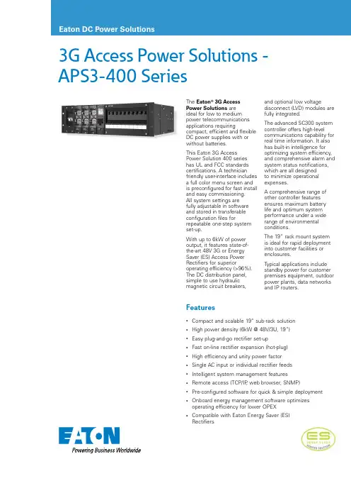
3G Access Power Solutions -APS3-400 SeriesFeatures•Compact and scalable 19” sub-rack solution •High power density (6kW @ 48V/3U, 19”) •Easy plug-and-go rectifier set-up •Fast on-line rectifier expansion (hot-plug) •High efficiency and unity power factor •Single AC input or individual rectifier feeds •Intelligent system management features •Remote access (TCP/IP , web browser, SNMP)•Pre-configured software for quick & simple deployment•Onboard energy management software optimizes operating efficiency for lower OPEX•Compatible with Eaton Energy Saver (ES) RectifiersThe Eaton ® 3G Access Power Solutions are ideal for low to medium power telecommunications applications requiringcompact, efficient and flexible DC power supplies with or without batteries.This Eaton 3G Access Power Solution 400 series has UL and FCC standards certifications. A technician friendly user-interface includes a full color menu screen and is preconfigured for fast install and easy commissioning. All system settings are fully adjustable in software and stored in transferable configuration files forrepeatable one-step system set-up.With up to 6kW of power output, it features state-of-the-art 48V 3G or Energy Saver (ES) Access Power Rectifiers for superioroperating efficiency (>96%). The DC distribution panel, simple to use hydraulic magnetic circuit breakers,and optional low voltagedisconnect (L VD) modules are fully integrated.The advanced SC300 system controller offers high-level communications capability for real time information. It also has built-in intelligence for optimizing system efficiency, and comprehensive alarm and system status notifications, which are all designed to minimize operational expenses.A comprehensive range of other controller features ensures maximum battery life and optimum system performance under a wide range of environmental conditions.The 19” rack mount system is ideal for rapid deployment into customer facilities or enclosures.T ypical applications include standby power for customer premises equipment, outdoor power plants, data networksand IP routers.Email:*****************/dcpowersolutionsEatonEMEA Headquarters Route de la Longeraie 71110 Morges, Switzerland © 2022 EatonAll Rights ReservedPublication No. PS154015EN March 2022Eaton is a registered trademark.All other trademarks are property of their respective owners.Eaton, CellSure, SiteSure, DCTools and PowerManager are trade names, trademarks, and/or service marks of Eaton Corporation or its subsidiaries and affiliates. All other trademarks are property of their respective owners.Follow us on social media to get the latest product and support information.Technical SpecificationsInputAC Supply†Nominal: 120V, 208-240V Operating Range: 90V – 275V** Output power derates below 175V AC.Power Factor†>0.99 (50 – 100% Output Current)Efficiency†APR48-3G : 92% (50 – 100% Output Current)APR48-ES : >96% peak,>95% (20% to 100% load, 230Vac)Total Harmonic Distortion<5% THD from 50% to 100% at load.OutputDC Output Voltage Range 43 – 57.5VDC OutputPower (maximum)†APR48-3G : 120V AC: 3.3kW @ 48V208-240V AC: 5.4kW @ 48VAPR48-ES : 120V AC: 3.45kW @ 48V208-240V AC: 6kW @ 48VEnvironmentalTemperature Range*Rated: -10°C – +50°C [14°F – +122°F]Extended: -40°C – +65°C [-40°F – 149°F]* Output current is derated above 50°C [122°F]MechanicalDimensions H,W,D3U [5.25”, 133mm], 19” [483mm] mounting, 14” [356mm]** A dditional clear space is required for exhaust air. Rear access is required for cable terminations.SystemSystem Controller SC300DC Distribution Module10-way circuit breakers (2 x Battery, 8 x Load).Load circuit breakers: Heinemann AMIR Series 5A,10A, 20A, 30A, 40A, 50A, 70A, 80A, 100A.Battery circuit breakers: Heinemann AMIR 100A or AMIP 120A.Communication FeaturesUSB direct*10BaseT Ethernet*, TCP/IP*, SNMP*, Modbus-TCP*, Modbus-RTU* and on board web server*RS232 to external PSTN or GSM modem (modem not included) SC300Low Voltage Disconnect (LVD)Battery disconnect: 200A internal.Rectifier Blank Panels For unused rectifier positions.OptionsRelay Rack BatteriesSoftwareDCToolsConfiguration software.Free download from:/downloads PowerManagerIIRemote control and monitoring softwareCertificationsAll products comply with International Standards including UL (US and Canada) and FCC (Class B) Verification.In the interests of continual product improvement all specifications are subject to change without notice.† P ower factor, efficiency, AC voltage range and output power is dependant on rectifier module fitted. Refer to the rectifier data sheet for more information.。
DVP-400(V0100)使用说明书(B5纸)合订本(第1版)_13_07_02

本手册适用于 DVP-400 系列 V0100 版产品 2012 年 05 月 10 日第一版
DVP-400V1.0 系列微机保护监控装置
使用手册
目
录
第一章 产品介绍.........................................................................................................................1 1.1 DVP-400 系列装置功能型号表................................................................................... 1 1.2 DVP-400 系列保护监控装置特点............................................................................... 1 1.3 DVP-400 系列各型号配备的保护功能....................................................................... 3 1.4 各型号配备的其它功能............................................................................................... 4 1.5 技术参数........................................................................................................................ 5 第二章 安装和接线.....................................................................................................................7 2.1 装置组成示意图............................................................................................................7 2.2 装置安装方式示意图................................................................................................... 8 2.3 装置最大尺寸图............................................................................................................8 2.4 屏柜面板开孔尺寸图................................................................................................... 9 2.5 外置 CT 结构图............................................................................................................10 2.6 装置的端子图及端子定义说明................................................................................. 11 第三章 面板操作及显示...........................................................................................................14 3.1 机箱面板说明..............................................................................................................14 3.2 按键操作说明..............................................................................................................14 3.3 菜单树型图..................................................................................................................15 3.3.1 DVP-411(2)/F 装置菜单树型图................................................................... 15 3.3.2 DVP-431/F 装置菜单树型图......................................................................... 16 3.3.3 DVP-441/F 装置菜单树型图......................................................................... 17 3.3.4 DVP-462/F 装置菜单树型图......................................................................... 19 3.3.5 DVP-464/F 装置菜单树型图......................................................................... 21 3.4 显示说明...................................................................................................................... 23 3.4.1 上电初始示意图............................................................................................. 23 3.4.2 主运行图.........................................................................................................23 3.4.3 功能主菜单.................................................................................................... 24 3.4.4 实时数据.........................................................................................................24 3.4.5 系统参数.........................................................................................................25
PSM 692数字式电动机保护测控装置技术说明书_V2.06

I
PSM 692 产品说明书版本修改记录表
7 6 5 4 3 2 1 序号 V2.06 V2.05 V2.03 V2.00 说明书版本号 改进版本 改进版本 改进版本 初始版本 修 改 摘 要 V2.06 V2.05 V2.03 V2.00 软件版本号 2011.05 2010.12 2006.11 2006.05 修改日期
III
6 装置信息代码表 .................................................................... 6.1 事件信息表 ...................................................................... 6.2 告警信息表 ...................................................................... 6.3 软压板信息表 .................................................................... 6.4 遥测量信息表 .................................................................... 6.5 电量信息表 ...................................................................... 6.6 遥信量信息表 .................................................................... 6.7 遥控量信息表 .................................................................... 7 装置二次接线示意图 ................................................................
MPS4000系列变电站综合自动化系统 技术及说明书

μMPS4000系列变电站综合自动化系统μMPS4000-230B微机变压器后备保护装置技术及使用说明书V6.3北京清大华康电子技术有限责任公司二零零六年三月目录目录 (1)1.概述 (3)2.μMPS 4230B主要功能 (4)3.主要技术要求和指标 (4)3.1工作环境条件 (4)3.2周围环境 (4)3.3电源 (4)3.4主要技术参数 (5)4.保护原理及功能说明 (6)4.1复合电压闭锁过流保护 (6)4.2零序过流保护 (7)4.3零序过压保护 (8)4.4间隙零序过流保护 (8)4.5 过负荷保护 (9)4.6 PT断线检测与报警 (9)4.7后备保护跳闸出口应用说明 (10)4.8保护逻辑 (11)4.9故障录波 (12)4.10手动分合闸操作 (12)4.11交流电量测量 (12)4.12脉冲电度测量 (13)4.13测量通道的软件校正处理 (13)4.14 SOE记录 (13)4.15硬件说明 (14)4.16操作回路 (17)5.定值与参数说明 (21)5.1定值清单 (21)5.2定值说明 (22)5.3测量参数表说明 (24)5.4脉冲电度计量的峰谷时段表 (25)5.5系统参数表说明 (25)6.装置结构与接线端子图 (26)6.1结构外形 (26)6.2面板按键与指示灯操作说明 (28)6.3后面板端子接线说明 (28)7.面板显示操作功能说明 (31)7.1屏幕显示操作功能一览表 (31)7.2系统信息显示 (31)7.3主屏幕显示 (31)7.4一级菜单 (32)7.5系统信息显示 (32)7.6常规显示 (32)7.7设置 (34)7.8记录查询 (38)7.9系统参数查询 (39)7.10测量校正 (40)7.11分闸操作 (41)7.12合闸操作 (42)7.13事故复位 (42)7.14就地远动切换 (42)1.概述μMPS 4000系列综合自动化系统是的新一代面向二十一世纪的变电站成套保护装置。
PS400系列智能型综合保护控制器

PS400系列智能型综合保护控制器产品概述PS400智能型综合控制器是在国电南京自动化股份有限公司消化国内外先进经验基础上研制的。
主CPU为高性能ARM单片机,速度快,集成度高,功能完善。
可以对电动机的过载、堵转过流、外部故障、缺相不平衡、欠压、过压、欠功率、接地或漏电等故障引起的危害予以保护。
并具有测量、通讯、操作控制电机起停等功能。
配上PSZ420智能操作显示模块可以显示电动机丰富的测量信息、报警信息、故障信息,可以进行保护定值、系统参数的设定,也可以在面板直接操作电动机起停机。
PS 400适用于操作交流50Hz、额定工作电压至660V的交流电动机等控制回路中的接触器,也适用于操作交流电操机构。
将电动机等设备的测量、保护、操作集成在一个机箱内,结构小巧,可在恶劣的工业环境下(如高、低温、震动、有害气体、灰尘、强电磁干扰等)长期可靠地运行。
可直接安装在低压控制终端PC或MCC柜中(1/4模数及以上各种抽屉柜),并具有远传、记忆各种操作或故障信息等功能,同时提供中央信号空接点。
该产品采用优化设计、调试维护极其方便。
PS400智能型综合控制器在国内首家采用了双Profibus现场总线冗余技术并支持DP/DPV1协议,可以直接与PLC进行无缝通信。
Profibus现场总线最高速率达到12Mbps,是目前最快的现场总线,已经成为我国第一个工业现场总线的国家标准。
主要特点★采用高性能ARM单片机,主芯片集成度高,功能丰富,使装置可靠性极大提高。
★选用14位的高性能A/D芯片,采样速度快,精度高。
★完善的自我诊断功能,不需人为干预,故障可定位到某芯片。
★最近100条事件记录及4条事故记录(包含6秒录波,故障跳闸前3秒,故障后3秒)。
★集保护、遥测、遥信、遥控功能于一体,可按功能就地安装。
★两个Profibus-DP(或RS485)通信接口,标准的通讯协议,双网冗余,一路故障时不影响另一路正常运行。
★在ECS系统的工程师站上通过Profibus通讯网络完成400V装置的功能设置与整定。
PS400系列保护测控装置说明书V1.42(Modbus)

V2.16 V2.15 V2.10 V2.09 V2.09 V2.08 软件版本号
2012-12-30 2012-07-24 2010-8-5 2010-1-7 2009-9-29 2009-7-13 修改日期
* 技术支持
电话:(025)51858272 传真:(025)51858972
* 本说明书可能会被修改,请注意核对实际产品与说明书的版本是否相符 * 2009 年 7 月 第 1 版 第 .............................................................................................................................................................. 5 1 概述 ............................................................................................................................................................................. 5 1.1 主要用途及方案 .................................................................................................................................................. 5 1.2 技术特点 ...............................................................................
HYP400微机可编程保护测控装置(4版)
浙江华仪电力自动化有限公司 2009、10
浙江华仪电力自动化有限公司保留修改本手册的权利,如有更改,恕不另行通知。
第 1 页 共 44 页
符号的使用 本手册包含的下列图标表示与安全相关的状况或其它重要信息:
电气预警图标:表示存在可能导致电击的危险。
3.保护元件符号功能说明 ...........................................................................................................................15 3.1 过压元件...............................................................................................................................................16 3.2 欠压元件...............................................................................................................................................16 3.3 过流元件...............................................................................................................................................16 3.4 欠流元件...............................................................................................................................................16 3.5 反时限元件...........................................................................................................................................17 3.6 过热元件...............................................................................................................................................18 3.7 保护控制字...........................................................................................................................................19 3.8 逻辑元件...............................................................................................................................................19 3.9 时间元件...............................................................................................................................................19 4.接线原理图及逻辑功能图 .......................................................................................................................20 4.1 HYP461 的接线原理图 ........................................................................................................................20 4.2 HYP461 的逻辑原理图 .........................................................................................................................20 4.3 HYP421 的接线原理图 .........................................................................................................................30 4.4 HYP421 的逻辑图................................................................................................................................30 4.5 HYP441 的接线原理图 ........................................................................................................................34 4.6 HYP441 的逻辑原理图 ........................................................................................................................34
电镁 MP-4000 电机保护多功能电机保护设备说明书
MP-4000motor protectionMulti-function motor protectionIntroducing Eaton’s MP-4000 motor protection relayEaton’s MP-4000 motor protective relay combines all the featuresyou need to ensure medium voltage motor protection, faultdiagnostics, power metering, and communication versatility intoone unique, cost-effective package. There’s no need for additionalrelays or unnecessary meters when you invest in the MP-4000.The MP-4000 expands upon industry-leading protection, controland diagnostics found in the MP-3000 by adding voltage inputsfrom voltage transformers (VTs). The VT inputs enable additionalprotection functions and metering such as under/overvoltage,negative sequence voltage, power factor and frequency. Otherupgraded features include new metering capabilities and newcommunication options such as Modbus T RTU and DeviceNet.EReliable construction, flexible features and user-friendly operationmake the MP-4000 an industry-leading motor protectionrelay powerhouse.2EATON CORPORATION MP-4000LED IndicatorsDetermineat a glancethe statusof MP-4000relay, trip andalarm targets Restricted AccessFunctions areprotected bysecurity coverwith meter sealProgram Button For inputting settings EmergencyOverride ButtonAllow motor to startin emergency situationsHelp ButtonComprehensivehelp featureright at thedeviceDisplay Mode andNavigation ButtonsQuickly access real-time information,relay settings andhistorical data, withminimal keystrokesThe Emergency Override default status is “disabled.” If enabled by the user, it will allowemergency starting by resetting the thermal bucket, start-inhibiting timers and counters.3EATON CORPORATION MP-4000Intel-I-T rip overload protection: precision and easeOnly the MP-4000 motor protection relay features the Intel-I-Trip, an algorithm created by Eaton to develop customer trip curves for both maximum protection and capacity use of your motor. The Intel-I-Trip overloadprotection algorithm provides adaptive trip characteristics based on motor temperature when motor RTDs are connected through an optional URTD module.Is developing a custom trip curve a difficult task? Not for the MP-4000. Simply enter the motor manufacturer’s data into the device, and it will provide you with the optimal curve for that specific motor. And, should you require assistance, the “Help” menu provides true user-friendly operational assistance.No programming technician or engineer needed. Simply let the MP-4000 do all the work.The MP-4000 offers complete metering and protection functionsin accordance with the IEEE device numbers listed in this diagramPowerful featuresLeading-edge voltage sag resistanceUnfortunately, power quality disturbances have become a way of life for modern plants and factories. The good news is that, with the right equipment, voltage sags do not have to disrupt protection for your equipment. The MP -4000 provides the industry-leading voltage sag ride-through (SRT) at 20 cycles and can easily withstand most power quality events. The MP-4000 will also withstand a typical utility reclosure, which lasts 15 to 20 cycles, without resetting. Now, a “light flicker” doesn’t mean your motor will stop running.4EATON CORPORATION MP-4000UL 1053 certifiedWhen it comes tomicroprocessor relays, safety should always come first. Eaton’s MP-4000 conforms to the UL T 1053 ground fault protection standard, thereby eliminating the need for a separate ground relay—saving you wiring, space, time and money.Conformal coating: standard protectionHarsh weather or environmental conditions are no reasons for your motor relay to malfunction. Eaton is the only company offering a protective, dielectric conformal coating, standard on the MP-4000, allowing the relay to stand up to the harshest of elements.Bottom line protection If you’ve been looking for a cost-effective solution that eliminates the need for redundant relays while simultaneously providinguser-friendly, flexible operational capabilities, you’ve now come to the end of your search. Eaton has built the MP-4000 on a foundation of stability, flexibility and reliability to provide you with the highest quality motor protection relay available.Armed/Disarmed:Maintenance without worry Periodic testing, settings changes and other maintenance tasks should not produce concerns about tripping the motor. The MP-4000’s Armed/Disarmed feature solves this typical relay problem. Arm the relay, and the motor remains protected. Disarm the relay, and it will indicate a trip condition without actually tripping the motor.Motor Start Profile intelligent controlThe MP-4000’s Motor Start Profile E provides start logic control to protect the motor against excessive starts or starting the motor before it has sufficiently cooled for both linestarters and reduced voltage starters. This feature can also be used to develop protection settings on old motors where data is not available.Better troubleshooting with advanced data logsAs the old saying goes, “Y ou don’t know where you’re going unless you know where you’ve been.” With the MP-4000, you can plan for the future because of its advanced event logging and activity monitoring systems. Motor currents, temperatures and conditions are consistently monitored and displayed either locally or remotely on your PC via optional Power Xpert T Server Core Software. The MP-4000’s event log provides motor operating records for the twenty most recent trips or alarm events, the one hundred most recent motor events, and the last four starts with accurate time and date stamping.The MP-4000 reduces downtime by taking the guesswork out of troubleshooting.5EATON CORPORATION MP-4000Optimizing your powersystemPower Xpert Architecture Eaton looks at your power system as a strategic asset— an approach we call PowerChain E solutions. We help you manage your power system for peak performance by integrating and optimizing the elements of your power system and ensuring that they align with your business goals. Eaton’s Power Xpert Architecture is the backbone of Eaton’s PowerChain Management. Power Xpert Architecture can transform your power system into an integrated, agile systemthat you can monitor, control and manage effectively andefficiently. The MP-4000 provides the information you need to assess how efficiently your motor is running and, in the event of a trip, to get it back online as quickly as possible. Power Xpert Server Core Software turns simple data into valuable information, empowering you to make informed operating and predictive maintenance decisions, troubleshoot, and increase reliability and uptime.Power Xpert Architecture lets you decide how much of your power system you want to integrate, and theappropriate integration method. Start small by monitoring one or two MP-4000s through a basic Web interface using a Power Xpert Gateway. Or easily connect the MP-4000 to the rest of your power management system—integrate it into a process control, facility management or enterprise- wide information system with the Power Xpert Server Core Software.Drawout case:Replacement without interruption With the MP-4000, evenreplacements do not have to slow down your operations. The optional quick-release drawout case allows you to pull out the relay for periodic testing or retrofits with no disruption to the process.6EATON CORPORATION MP-4000Cost-effective MD-3000 optionTired of buying all those relayswith protective functions thatyou seldom use? Eaton knowsthat and offers you a cost-effective package with just whatyou need. With the MP-4000,you have no worries abouthaving to map your protectionsto specific outputs or having toknow Boolean logic to controlyour motor. The MP-4000 is easyto use and configure. On theother hand, if you require specialprotections such as a motordifferential protection, weoffer you our MD-3000 relay,designed in conjunction withthe MP-4000, to protect yourlarge motors.7 EATON CORPORATION MP-4000Eaton’s Electrical Sector isa global leader in power distribution, power quality, control and automation, and monitoring products. When combined with Eaton’s full-scale engineering services, these products provide customer- driven PowerChain E solutions to serve the power system needs of the data center, industrial, institutional, public sector, utility, commercial, residential, IT, mission critical, alternative energy and OEM markets worldwide. PowerChain solutions help enterprises achieve sustainable and competitive advantages through proactive management of the power system as a strategic, integrated asset throughout its life cycle, resulting in enhanced safety, greater reliability and energy efficiency. For more information, visit /electrical.Eaton Corporation Electrical Sector1111 Superior Ave. Cleveland, OH 44114United States877-ETN-CARE (877-386-2273) © 2010 Eaton CorporationAll Rights ReservedPrinted in USAPublication No. BR02602001E / Z10383 December 2010PowerChain Management is a registered trademark of Eaton Corporation.All other trademarks are property of theirrespective owners.。
PS 640U系列保护测控装置使用说明书V1.22(1)
1.2.5 接点容量 a) 操作回路接点闭合容量:DC 220V 5A; b) 信号回路接点闭合容量:DC 220V 5A; c) 信号回路接点切换容量:DC 220V 60W(阻性负载) 。 1.2.6 状态量电平 a) CPU 模件中输入状态量电平 b) DIO 模件的输入状态量电平 1.2.7 装置通信接口 以太网波特率:100Mbps。 1.2.8 测控功能技术性能 a、 工频模拟量测量精度 — — — — — — — — — — — — 交流电压、交流电流:±0.2%(0.2 级) , 有功功率、无功功率:±0.5%(0.5 级) , 相角或功率因数:±0.5%(0.5 级) , 频率:±0.01 Hz; 电流: (0~1.2)IN, 电压:(0~1.2)×100 V, 三相有功功率:-(1.2×UN.L 3 ) IN W~+(1.2×UN.L 3 ) IN W, 三相有功功率:-1.2× 3 UN.LIN W~+1.2× 3 UN.LIN W, 三相无功功率:-(1.2×UN.L 3 ) IN Var~+(1.2×UN.L 3 ) IN Var, 三相无功功率:-1.2× 3 UN.LIN Var~+1.2× 3 UN.LIN Var, 功率因数:-1.00~+1.00, 频率:45 Hz~55 Hz; DC 220V DC 110V DC 220V DC 110V 动作范围:143V~300V,返回值:121V, 动作范围:72V~300V,返回值:55V; 动作范围:143V~300V,返回值:121V, 动作范围:72V~300V,返回值:55V。
国 电 南 自
Q/GDNZ.JB051-2011
PS 640U 系列 保护测控装置 使用说明书
国电南京自动化股份有限公司
PSM 641U电动机保护测控装置技术说明书
国电南自DL/T 1075 PSM 641U电动机保护测控装置技术说明书国电南京自动化股份有限公司GUODIAN NANJING AUTOMATION CO.,LTDPSM 641U电动机保护测控装置技术说明书V 1.24国电南京自动化股份有限公司2013年03月版本声明本说明书适用于PSM 641U电动机保护测控装置V1.24及以上版本。
PSM 641U电动机保护测控装置产品说明书版本修改记录表10987654321 V1.24 初始版本PSM 641U V1.24 2012.11序号说明书版本号修改摘要软件版本号修改日期* 技术支持电话:(025)51183073传真:(025)83537200* 本说明书可能会被修改,请注意核对实际产品与说明书的版本是否相符* 2012年12月第1版第1次印刷* 国电南自技术部监制目录1概述 (1)1.1 适用范围 (1)1.2 装置型号及其保护功能配置 (1)1.3 测量和控制 (1)2技术参数 (2)2.1 保护元件精确工作范围 (2)2.2 保护元件定值误差 (2)2.3 保护整组动作时间 (2)2.4 通信接口 (2)3保护功能及原理 (3)3.1 电动机起动 (3)3.2差动保护 (3)3.3 过热保护 (5)3.4 过电流保护 (6)3.5 过负荷 (6)3.6 非全相运行保护 (7)3.7 反时限元件 (7)3.8 堵转保护 (7)3.9 F-C闭锁功能 (7)3.10 零序过电流保护 (7)3.11 零序电压保护 (7)3.12 低电压保护 (8)3.13 过电压保护 (8)3.14 非电量保护 (8)3.15 低频率保护 (8)3.16 失步保护 (8)3.17 非同步冲击保护 (8)3.18 PT断线 (9)4端子说明 (10)4.1 基本型配置端子图 (10)4.2 D型配置端子图 (11)4.3 S型配置端子图 (12)5定值整定说明 (13)5.1 基本型配置保护定值清单及说明 (13)5.2 D型配置保护定值清单及说明 (16)5.3S型配置保护定值清单及说明 (19)6装置信息代码表 (24)6.1 事件信息表 (24)6.2 告警信息表 (24)6.3软压板信息表 (25)6.4 遥信量信息表 (27)6.5 遥测信息表 (28)6.6 遥控量信息表 (28)7装置二次接线示意图 (29)7.1 基本型配置示意图 (29)7.2 D型配置示意图 (30)7.3 S型配置示意图 (31)1 概述 1.1 适用范围PSM 641U 电动机保护测控装置是对电动机的相间故障、接地故障以及不正常运行提供全面保护,同时集成了各种测量和控制功能的多功能成套装置。