
iKonMac C8.C18使用手册
油墨
油墨
墨水供应采用墨盒,更换墨盒简单,干净,便利。 更换墨盒时,按下墨盒固定弹片,然后拉出旧的墨盒,插入新墨盒,使挤压孔朝下。 当墨盒穿入时,会有一点阻力,但不要太用力。如果墨盒安装不太容易,请检查挤压孔是否朝下,并且墨盒凸起的部 分是否朝前。 如果更换墨盒的时间只有几秒钟,那么喷印机可以继续喷印,并且空气不会被吸入油墨孔;如果被吸入油墨孔,那么 就需要将其消除,即挤压出空气。 如果觉得没把握,请关机后更换油墨盒。
喷印机
3
速度
3
墨盒
3
安装喷码机 ....................................................................................................................................................................... 5
+
4.
5.
修改系统时间。
3. 退出喷印状态。 4. 保存时间设置并退出。
3. 在主菜单状态,
控制光标位置,
改变当前数值。
6.
+
7.
4. 在喷印状态,
喷印宽度,
改变喷印延迟。
恢复当前喷印信息到 00 条,同时计数器当前值变成 0
iKonMac C8/C18 系列喷码机使用手册 10
启动喷码机
启动喷码机
机器在任何时候都必须安装墨盒,否则 会污染喷印机油墨系统。在任何时候都 不能把手指伸入墨盒槽,因为槽内尖锐 的针会损伤手指。
光电传感器
光电传感器必须安装于喷印头的前方,不管是左边或右边,要根据产品的运动方向而定。 当光电传感器感应到该产品的起始边时, 喷印机开始计时,在延迟时间到达时开始喷印。 产品与产品之间要有间隙,否则传感器将不工作,喷印机也不喷印。
iKonMac C8/C18 系列喷码机使用手册 1
喷印机
介绍
iKonMac 为易可玛喷印技术有限公司商标 C8/C18 本机的型号为 C8/C18,8/18 为本机可喷印的最大高度(单位:毫米) C8 最大喷印高度 8mm,C18 最大喷印高度 18mm.
喷印机
C8/C18 喷印机是用于喷印文字(包括点阵以及实体中英文)、图形的高解像喷墨印字机,喷印字高 2 mm -18mm。
油墨的选择
29
快干油墨:用于非渗透性表面
30
iKonMac C8/C18 系列喷码机使用手册
维护保养 ......................................................................................................................................................................... 31
使用手册图例参考表
1
介绍 ................................................................................................................................................................................... 3
控制光标位置,
改变当前数值。
6.
+
7.
2. 在喷印状态,
喷印宽度,
改变喷印延迟。
恢复当前喷印信息到 00 条,同时计数器当前值变成 0
iKonMac C8/C18 系列喷码机使用手册 9
iKonMac C18 键盘功能表
iKonMac C18 键盘功能表
键盘 1.
功能 开始喷印。
2.
暂停喷印。
3.
iKonMac
高解像喷码机 使用手册
型号 C8/C18 系列
iKonMac C8/C18 系列喷码机使用手册
V80320
目录
使用手册图例参考.................................................................................................................................................... 1
控制喷头与 产品的间距在 5-8mm 之间
挡板带倒角,使纸 箱边角不破损以致于损 坏喷头
固定架
固定架必须坚固,不振动。
耗材
C8/C18 喷码机不需使用压缩空气。 C8/C18 喷码机 必须水平安装,否则容易造成墨水滴落或墨水不能正常喷出。
电压设置
C8/C18 喷印机使用电压(交流 220 伏/60H)
使用 C8/C18 型喷吗机必须注意以下事项
33
开机
33
关机
33
长期不使用的保养
33
长时间停机重新使用时的操作方法(与新机开始使用的方法一样)
34
机器包装及运输的操作方法
34
日常使用注意事项
34
其他注意事项:
34
iKonMac C8/C18 系列喷码机使用手册
使用手册图例参考表
使用手册图例参考
使用手册图例参考表
关机
连续喷印过程中,喷头上的油墨不会干。
正常关机只是把电源开关关闭 。
长时间关机, 建议装上喷头保护片,并使用包装材料包好喷头,但不能接触喷印孔(黄色条状)。关机期间不必取出 墨盒,否则污染物会进入油墨系统。
关机时间超过三天以上,维护请参阅日常保养节。
不论在任何情况下,都不能用任何材料(无论多柔软)擦喷印,只能使用 iKonMac 公司提供专用清洗剂,否则损坏喷印头。
光电传感器装在 左边
产品运动方向
喷头保护传感器装 在右边
产品运动方向
iKonMac C8/C18 系列喷码机使用手册 6
选配喷印头
选配喷印头
当要向下喷印或在有限制的空间喷印时。 在安装喷印头时,一定要注意喷头与墨盒之间的相对位置: z 如果喷头的安装位置高于建议的位置,那么喷印机将不能喷印。 z 如果喷头的安装位置低于建议的位置,那么油墨将从喷头漏出。
打开喷码机开关,启动喷码机. z 打开机器电源开关。 z 喷码机显示主菜单如下
使用喷码机
此时屏幕右上方显示传送,此时可以使用 Jetstar 软件传输信息(参阅使用 Jetstar 软件节) z 使用瓶装清洗剂喷洗喷头,一般挤压(2-3 次)。 z 请不要使用其他任何液体,否则将损坏喷头。 z 挤压油墨盒(参阅挤压油墨盒)清除喷头上的清洗液。 z 将喷头保护片及排水孔中的多余的墨水除去,千万不能触碰喷头,无论您使用什么材料,也无论您使用的 材料多么柔软,都将永久地损坏您的喷头。
iKonMac C8/C18 系列喷码机使用手册 3
环境与位置
安装喷码机
环境与位置
环境
使用稳定的电压与电流,避免瞬间高压与干扰。
干扰
不要安装喷印机在电磁场辐射区附近,例如:高频封口机、金属探测器等。
安装
为了能获最好的喷印质量,请将喷印机安装于流水在线,并使被喷印的产品稳定通过流水线 。 任何翘起的边角通过喷印机头,都有可能降低喷印质量。 在产品与产品之间请保持一定的间距,不要靠在一起或迭在一起,以便光电传感器(电眼)能正常工作。 C8/C18 喷码机喷印头可朝下或水平安装.
编号 A. B. C. D. E. F. G. H. I.
种类 菜单 按钮 对话框 对话框内的控件或栏目(名称) 特殊注意
实例 【配置Î层】 确定、取消、OK 网上邻居 属性 应用 手持控制器
特征 中括号+箭头 边框+灰底 双边框+灰底 灰底 红色字+粗体+斜体
说明/助忆 有时会有三层 看似可按 类似对话框的样子 出现在对话框内的各种组件 帮助阅读的需注意的名称
iKonMac C8 键盘功能表
9
iKonMac C18 键盘功能表
10
使用喷码机 ..................................................................................................................................................................... 11
启动喷码机
11
设置系统时间
11
iKonMac C8/C18 系列喷码机使用手册
选择喷印信息
11
挤压油墨盒
12
挤压油墨盒原理
12
挤压油墨盒操作方法
12
喷印
13
设置信息喷印延迟
13
设置信息喷印宽度
13
使用同步器
14
人工设置喷印宽度
14
设置计数器当前值
14
恢复出厂默认设置
14
使用 Jetstar 软件............................................................................................................................................................. 15
喷头孔底部 30-50
机器底部 喷头孔底部 30-50 机器底部 安装喷印头时,喷印头孔底部与机器底部的距离为 30mm~ 50mm,高于 50mm 喷印头将不喷印; 低于 30mm,墨水将 从喷印头流出。
iKonMac C8/C18 系列喷码机使用手册 7
导航系统8 Getting Started 用户指南说明书

System ControlsMENU buttonPressing this button changes the display from the current instructions to the Entering a destination by screen or the Calculate route to screen.MAP/GUIDE buttonPressing this button switches thedisplay between a map screen and the guidance or direction list screen.A/C-INFO buttonPressing this button displays the screen for A/C manual controls, and for selecting Set-up, Trip Computer, Calendar, Calculator, or Voice Command Help.CANCEL buttonPressing this button cancels the current screen and returns to the previousscreen display.A/C-INFO button CANCEL button ZOOM buttonsMENU button MAP / GUIDE buttonZOOM (IN/UP)/ (OUT/DOWN) buttonsWhen you are displaying a map, these buttons allow you to change the scale. ZOOM IN reduces the scale, showing less area with greater detail. It is also used to scroll UP a page in a list. ZOOM OUT increases the scale, showing more area with less detail. It is also used to scroll DOWN a page in a list.Other buttonsSee the vehicle owner’s manual for information on the rest of the buttons.ScreenAll selections and instructions aredisplayed on the screen. In addition, thedisplay is a “touch screen” –– you canenter information into the system bytouching the images (icons) on thescreen with your finger.For example, when you need to enter astreet name, a keyboard will bedisplayed. You can “type in” the streetname by touching the individualcharacters on the screen.When you select Reverse, the rearcamera is activated, and displays whatis behind you on the screen. While inReverse, the navigation buttons and“touch screen” are disabled.Clean the screen with a soft, dampcloth. You may use a mild cleanerintended for eyeglasses or computerscreens. Harsher chemicals maydamage the screen.JoystickThe joystick moves left, right, up, anddown. Use the joystick to move thehighlighting around the display, toscroll through a list, or to look around adisplayed map. After making aselection in a menu or list, push in onthe joystick to enter the selection intothe system.In almost all cases, you can enter aselection into the system by pushing inon the joystick, or by touching theappropriate image on the screen.Using the Voice Control System Most of the system’s functions can be controlled by voice commands. The voice control system is activated with the TALK button. To control your navigation system by voice, press and release the TALK button, wait for the beep, then give a voice command. Once the microphone picks up your command, the system changes the display in response to the command and prompts you for the next command. Answer the prompts as required.If you do not give a command within about three seconds after pressing the TALK button, the voice control system turns off.If you hear a prompt such as “Pleaseuse the touch screen to...” or “Pleasechoose an area with the joystick.” thesystem is asking for input that cannotbe performed using the voice controlsystem.If the system does not understand acommand, it responds with “Pardon,”“Please repeat,” or “Would you sayagain.” If the system cannot perform acommand or the command is notappropriate for the screen you are on, itsounds a beep.Anytime you are not sure of what voicecommands are available on a screen,you can always say “Help.” at allscreen except the information screen.The system then reads the list ofcommands to you.When you speak a command, thesystem generally either repeats thecommand as a confirmation or asks youfor further information. If you do notwish to hear this feedback, you can turnit off. See Voice Feedback setting onSet-up screen 3.Improving Voice RecognitionTo achieve optimum voice recognition, the following guidelines should be followed:NOTE: Make sure the correct screen is displayed for the voice command that you are using. See Voice Command Index on page 86.•Close the windows and the sunroof.•Set the fan speed to low (1 or 2).•Adjust the air flow from the dashboard vents so they do not blow against the microphone on the ceiling.voice command.•Give a voice command in a clear, natural speaking voice without pausing between words.•If the system cannot recognize your command, speak louder.•If the microphone picks up voices other than yours, the system may not interpret your voice commands correctly.•If you speak a command with something in your mouth, or your voice is either too high or too husky, the system may misinterpret your voice commands.• After pressing the TALKwait for the beep, then give abutton,Selecting an Item (Button) on the ScreenOn most screens, there are items that can be selected (like buttons with titles such as OK or Return). To select an item on any screen, do one of the following:••Touch the desired item on the screen.•Move the highlighting to the desired item with the joystick, then push in on the joystick.Tip: If buttons are very dark colored, this means that they cannot be selected.Selecting an Item in a ListTo scroll through a list, do one of the following:•Use the joystick to scroll through the list item by item.•Use the voice control system and say “Next.” or “Previous.” or use the triangles in the upper right corner of the screen or the ZOOM buttons to scroll through the list page by page. If you cannot find the desired name, or have made an error, return to the previous screen by pressing the CANCEL or the BACK button.To select the desired item in the list, do one of the following:•Use the voice control system, and say the number of the desired item.•Touch the item on the screen.•Use the joystick to move the highlighting to the item, then push in on the joystick.Use the voice control system and say the name of the desired item. Every selectable item on the screen, except keyboard keys and some listed items, is recognized by the voice control system.Using the On-screen KeyboardWhen the system needs input from you,the display changes to a keyboard.Use the displayed letters to enter the information. Enter each letter by doing one of the following:•Touch the desired letter on the screen.•Move the highlighting to the desired letter with the joystick, then push in on the joystick.Each entered letter will appear at the top of the display. Use Space to enter a space between words. Use Delete to erase a letter entered incorrectly.As you enter the letters, the system match the letters you are entering. As a result, you will notice that some letters are no longer available.When the system finds only one entry that matches, it completes the entry of the name for you. If the system finds more than one entry that matches your input, the system displays a list.Tip: If you are unsure of the spelling of a name, enter the letters that you are sure of, and then select LIST . The system displays a list of names that most closely matches your input.You can change between alphabet and a regular keyboard (QWERTY). See Keyboard Layout on Set-upscreen 3.searches the database for words thatSystem Start-upWhen you turn the ignition to ON (II),it takes several seconds before the navigation system turns on the display.The first screen to appear is the Acura Navigation System logo screen. The screen then changes to the disclaimerscreen:NOTE: The OK button does not appear immediately. If appears after the software is loaded.Read this disclaimer carefully so you understand it before continuing. Push in on the joystick, or touch OK , and the map screen will appear on the display.The “OK” cannot be activated by voice.If you do not press the joystick or touch OK , the screen will go dark after 30seconds. To return to the disclaimer screen, press any navigation or voice control button.NOTE: If you do not select OK on the screen, certain functions of thenavigation system will not be available.See the System Function Diagram on page 18.If you have entered any Calenderreminders, they are displayed after you select OK.The Calendar reminder screenremains displayed until you select OK ,or press the Cancel button.If you select OK , the reminder will not show up again. If you wish to have the reminder show up again later in the day, go to Calendar in theIf you press the Cancel button, the you start the vehicle (on the same day).NOTE: The system only displays calendar reminders on the date you selected when you created the calendar entry. Messages do not accumulate, or get displayed on days other than the date it was originally set to display on.Information screen, and set Reminder message will be displayed the next time to ON .(see page(Mile or Km per half inchappear only when youZOOM IN or OUT.)42)(Use voice command "Display thecurrent location." or touch the iconto show current location.)(see page 43)Map FeaturesDark Green: ParkLight Gray: HospitalBrown: Shopping Mall/UniversityGreen: Golf CourseGray: Airport/Stadium/BusinessBlue: Body of Water"Breadcrumbs"(see Track OffroadPosition 45)Acura DealerHonda DealerGrocery StoreHotel/MotelSchoolHospitalRestaurantPost OfficeGas StationATMMap Screen LegendWhite: No Signal (seeAccessories Precautionon page 3)Map Overview on page 4,or Unverified Routing on page 39)Red: Interstates or FreewaysBlack: Verified RoadLight Brown: Unverified RoadMap Screen DescriptionUse the ZOOM buttons to change the scale of the map. Zooming in increases the detail, while zooming out gives you a view of a wide area. After changing the scale, give the system a few moments to update the display.In the three most detailed map scales (1/20, 1/8, and 1/2 mile, or 80, 200, and 800 meter), the map can be oriented with north pointing up (North up) or with the way you see it out the front window (Heading up). The red arrow in both heading symbols always point north.You can switch between the two by saying “Display North up.” or “Display Heading up.” or by touching the North pointer icon in the upper corner of the screen.In the larger map scales (above 1/2 mile or 800 meter scales), the map is always oriented with north facing upward. You cannot change the orientation.To view other areas on the map, movethe joystick left, right, up, or down. Themap will shift in that direction. Toreturn the map to your current location,press either the MAP/GUIDE, theCANCEL, or the BACK button.The display automatically changes tothe map screen when you reach yourdestination. Press the MENU button toreturn to the Enter destination byscreen.Displaying Current LocationYou can say “Display current location”or touch the vehicle position icon atany time to see the current address,latitude, longitude and elevation. Thescreen will change to:NOTE: If the elevation is missing, thesystem is lacking the proper GPSinformation to display it.You can say “Save current position.” orselect Save Current Location on thescreen to save the current location inPrevious Destinations.Select Return to return to the previousscreen.Getting StartedSystem Function DiagramThis diagram shows the features of the navigation system starting at the center and working outward in layers. The navigation program starts at “Key ON,”and then displays the globe screen (blue). Once the Disclaimer screen (pink) is acknowledged, the yellow portions of the diagram become active. If OK is not selected, the yellow portions of the diagram will not be available. However, some functions of the INFO and SET UP buttons, and all functions of the AUDIO and A/C buttons (white) can be accessed immediately after the Disclaimer screen (purple) without selecting OK. The items above the map screen show various methods to begin a destination, such as “Go Home.” Once you begin driving to your destination (orange), you are provided with map/voice guidance, routing cautions (in unverified areas), and a directions list. While driving to your destination, use the voice control system as much as possible to interactwith the navigation system (green).Navigation System18。
迪莱克电子产品说明书

81,7(' 67$7(6 ZZZRPHJDFRP 7&20(*$
6WDPIRUG &7
&$1$'$ ZZZRPHJDFD /DYDO 4XHEHF 7&20(*$
81,7(' .,1*'20 ZZZ RPHJDFRXN 0DQFKHVWHU (QJODQG
Transmitters
Model Series
TX1501/1502 TX70 TX1503/1504 TX86
TX66A/ PRTXD TX67A TX62/TX63 TX64/TX65
TX69/ TX41 TXDIN101
Base Price
£285
£218
£214
£261
£198
£231
£198
£64 N-10
-
TX91A TX92A
£99
N-11
J, K, T, E
TX93A TX94A
£49.50
N-12
-
TX91 TX92 £126
N-13
J, K, T, E R, S
TX93/TX94 TX900 TX95 Series TX92G
£65
£116 £107
N-14
N-15 N-16
Y
Power
12 to 80 Vdc
9 to 50 Vdc
12 to 30 8 to 32 12 to 48
Vdc
Vdc
Vdc
12 to 42 Vdc
12 to 42 115 Vac/ 13 to 36
Vdc
230 Vac Vdc
Protection Head HEP-TX70 EPH
ICP DAS WinCon8000 Series 硬件用户手册说明书
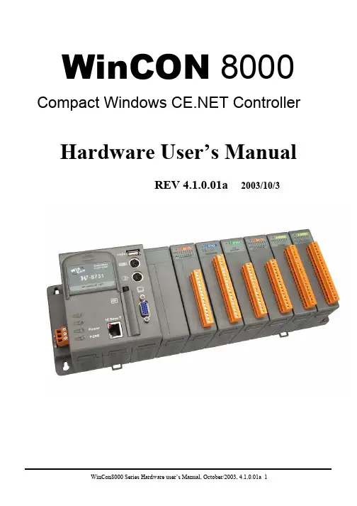
• WinCon 8000 Series
The WinCon 8000 is the flagship compact embedded controller manufactured by ICP DAS. Its leading technology gives you all of the best features of both traditional PLCs and Windows capable PCs. The WinCon 8000 system is powered by Windows and brings Windows programming style and skill into the world of PC-based PLCs. Application developers can directly develop their own programs in Microsoft’s Visual Studio .NET and Embedded Visual tools with the WinCon SDK, and then download them into WinCon 8000 for use. Or, they can port their favorite SCADA software onto WinCon 8000 for even easier application development. For SCADA applications, we also provide a product model embedded with InduSoft Web Studio run-time version to meet this need.
Ikan CB8 Canvas Bendable LED Panel 用户指南说明书

Quick Start Guide1 x CB8 Bi-color LED Panel Light1 x 5/8” Baby Pin with 90 degree Mount Holes1 x Controller box1 x Egg Crate1 x Hanging Strap1 x Power Cord1 x Power Supply1 x Soft Box1 x X-Holder with Ball MountGetting StartedThank you for buying the CB8 Canvas Bendable Panel Light from Ikan. Please carefully read the instructions and guide before operating the products. The guide includes product usage and maintenance. When you operate the product, please make sure that you have read the instructions carefully. All the content of the manual is based on up-to-date information; technical data subject to change without notice.Safety Instructions1.Connect the AC power cable to the controller box before plugging into the power source. You risk electrocution by not following this instruction.2.Don’t drag cables with excessive force. Any repairs on the products should be performed by Ikan technicians. Users should not remove the powersupply, or substitute a different power supply. This might damage the unit and will not be covered under warranty.3.Be sure that the power is off before connecting and changing the fixture head or disconnecting your cable from the power source. We recommend usingIkan connecting cables and connectors to avoid electrical shock.4.The voltage shouldn’t exceed the value in the technical specifications. If the voltage is greater than, or less than the regulated values, it could damagethe product.OverviewThe care and cleaning of the Canvas Bendable LED light. The CB8 should be rolled up and placed back into the carrying bag when not in use. The LEDs should be facing out when placed into the carrying bag. The two ends of the Canvas light should meet.If the LED’s should get dirty or covered in dust the unit can be cleaned with mild soap and water on a damp cloth.DO NOT SUBMERGE THE UNIT IN WATERConnecting the 4 prong cable between the controller box and the panel light.Align the male and female plugs so they line up and screw together until the cable is tight.Installation of the X-Holder with ball mountThe X-holder should be loose before inserting the struts into the hook & loop corners.1.Place the struts into the hook & loop flaps at the corners of the panel.2.Place them in opposite of each other for them to stay in place.3.Tighten the tension knob at the center to keep the struts locked in place.Color temperatures for today’s film and TV production are 5600K (daylight) and 3200K (tungsten). Ikan developed the CB8 Bendable Light to handle both these temperatures. With patented technologies, the CB8 offers a professional and customizable LED light source. In addition, the light features coolingflex system for optimizing heat dissipation. Specifically, the CB8 offers the following features:1.The 0-100% brightness incremental adjustment of the 2800K-6500K temperature enable fine-tuning your color range.2.A panel of 336 Bi-color led light gives out 200FC of light.3.Ultra-low noise and active cooling technology contribute to excellent thermal stability.4.The bright LCD readout is easy to view, enabling smooth adjustment of functions.5.Digitally adjustable knob allows you to adjust menu settings quickly and accurately.6.AC/DC power control box allows the light to be powered by battery or DC power supply.7.The softbox with grid cloth and 60 degree egg crate is included with the light.When placing the light mount on the 5/8” baby pin, this allows you to adjust the light in any desirable position.Note: To avoid damage to the LED’s, place the panel light LED side down on soft material.InstructionsAppearance & Structure - LightCB8 is illustrated as follows5/8 Receiver: attaches to a stand or a 5/8” baby pin w/90 degree holes Mount: Adjustable lighting directionHook & Loop around the edge of the lightScreen Display FuctionsIllustration of light’s dimmer:Color Temperature BatteryBrightnessColor : 4600K B:100%Bright: 88%Installation & Power Supply1.Ensure power is off before setting up light.2.Place the light on the Ikan customized stands, release the tension knob on the 5/8” receiver, adjust the light in the desired direction, and then tighten the tension knob on the 5/8” receiver.3.When connecting the power cords, plug the 4-pin XLR power cord into the controller box.Appearance & Structure - Control BoxPower switch: Turn on/turn off powerAC 110-220V Power Connector: Connecting with 110-220V power cable.LED Display: Changing the brightness 0-100%, changing the color 2800K-6500KColor Knob: Adjust the color from 2800K-6500K (press in on button to control the Warm white 0-100% and press brightness to control Cool white 0-100%)Brightness Knob: Adjusts brightness from 0%-100%Notice & Maintenance•The CB8 working temperature range must be regulated. Overheating will reduce the LED working life. Please allow adequate ventilation when using the Canvas light.•Products must be placed on a stable, dry, flat surface. Avoid exposure to sunlight and operating in an environment with high humidity or extreme moisture levels.•Don’t beat, knock or shake the lighting equipment during the operation.•If the CB8 isn’t working normally, please contact the Ikan repair department. Please don’t disassemble/re-assemble by yourself.•Please place the CB8 in a cool and dry place when you don’t use it for an extended period of time.What’s in the box?Please carry and place the packing box carefully. Check the lighting equipment and accessories upon opening the box. Please contact us if anything is damaged or missing. Please save the packing materials for replacing and repairing the products in the future.A.Battery Release ButtonB.Power on/off SwitchC. Color Adjustment KnobD. Brightness Adjustment KnobE.LCD Display ScreenEBAC DSpecifications Electrical Specifications TroubleshootingOptional AccessoriesSome other products that work well with the CB8 available from Ikan include:IBG-STND IBG-SB15 CP-STND-V3 HD-STND-V2Stand BagSaddle Sandbag & Weight Bag - 15 lb Compact Light StandHeavy Duty Light StandFailure Failure Cause TroubleshootingUnit Won’t Turn On The power is connected incorrectly orthe power switch in not turned on.Turn on the light with the switch on the controller box. Make sure the unit is plugged into AC power.During the operation lamp is out.The unit may have malfunctioned.The unit’s connecting cable may not beproperly secured. Try turning the control box off th e n on again.The cable can be disconnected and then reconnected.Learn MoreMore dynamic information at official website: SupportContactemail:********************CONDITIONS OF WARRANTY SERVICE• Free service for one year from the day of purchase if the problem is caused by manufacturing errors.• The components and maintenance service fee will be charged if the warranty period is expired.Free Service will not be Provided in the Following Situations:(*Even if the product is still within the warranty period.)• Damage caused by abuse or misuse, dismantling, or changes to the product not made by the company.• Damage caused by natural disaster, abnormal voltage, and environmental factors, etc.©2018 ikan Corporation. All rights reserved。
Ikon中文操作手册(WinCE)
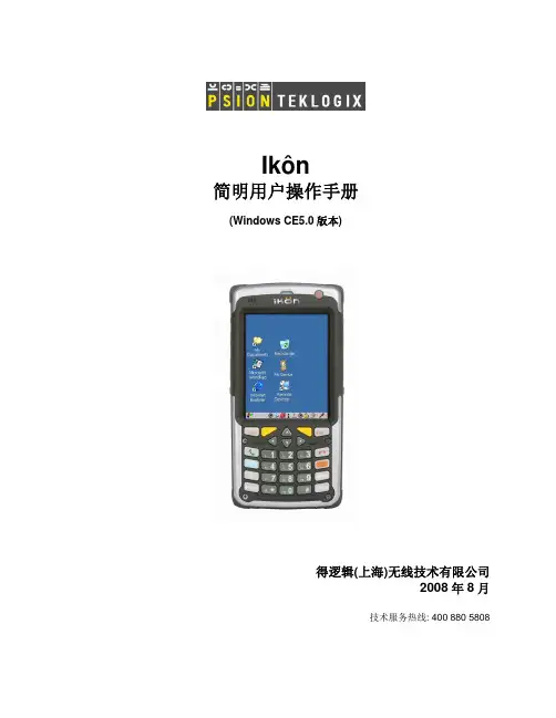
Ikôn简明用户操作手册(Windows CE5.0版本)得逻辑(上海)无线技术有限公司2008年8月技术服务热线: 400 880 5808© 得逻辑(上海)无线技术有限公司版权所有,2008年。
本文档及其包含的信息,其知识产权归加拿大得逻辑有限公司,未经该公司或其中国子公司得逻辑(上海)无线技术有限公司书面许可,不得复制或传播。
Windows®及 Windows标志是美国微软公司的商标或注册商标。
得逻辑(上海)无线技术有限公司技术服务热线: 400 880 5808目 录第1章 Ikôn手持终端简介 (1)1.1概述 (1)1.2IKON的性能参数 (2)1.3IKON手持终端的外形和款式 (4)第2章开始使用Ikôn手持终端 (6)2.1IKON 开机和关机 (6)2.2更换电池 (6)2.3给电池充电 (7)2.4重新启动IKON (7)2.5开始使用WINDOWS CE (8)2.6检查条码扫描器是否正常工作 (11)2.7IKON和PC互相传递数据 (11)2.8使用IKON的键盘 (12)2.9了解IKON的指示灯 (16)2.10检查电池容量和状态 (16)2.11打开输入面板(软键盘) (17)2.12系统整体备份与恢复 (18)2.13管理存储设备 (19)2.14触摸屏校正 (22)2.15如何调节显示器亮度 (22)2.16调节扬声器音量 (24)2.17键盘属性 (24)2.18使用GSM和GPRS/EDGE (29)2.19设置蓝牙 (31)2.20配置无线局域网 (33)2.21图像仪设置 (36)2.22扫描器设置 (39)第3章 IKôN手持终端的外部设备和配件 (42)3.1照相机 (42)3.2电池 (42)3.3GPS模块 (42)3.4便携式佩件 (43)3.5充电器和扩展设备 (44)3.6车载支架 (47)附录1 :扫描器和图像仪规格 (50)附录2 :IKON电池规格 (51)附录3 :IKON和外部接口 (52)第1章 Ikôn手持终端简介1.1 概述IKON将标新立异的功能性和灵活性融入到一个紧密型的、具有行业尖端的人性化设计的、具有美学理念和简便易用的新颖模式中。
ZEISS IKON Contaflex-B 摄影机操作手册说明书

®
Instruction manual
Contaflex ~B
For your own pleasure and enjoyment
in this fine photogrophic instrument, we urge you to read these instructions thoroughly and practice ha!ldling your new camera before loading your first film. Fold out the inner flaps so that as you read you can easily see each control and each reference number. Practice every operation until you are familiar with it so that later on you can operate the camera without difficulty. Consult your photo-
19 ZEISS JESSAR f/2.8,50 mm interchangeable lens
20 Film speed scale (ASA) 21 Film speed setting mark 22 Filter corrector
Reference numbers 23-39 refer to the illustration on th e rear cover flap.
removed when using the interchangeable film back) 27 Setting lever for delayed-action release (V) a nd X
Concens 线性電子酥器用戶操作手冊说明书
GBU S E R M A N U A LiconLinear In-line ActuatorU S E R M A N U A L | icon | March 2022 | 1i c o nCheck for updates at ContentsIntroduction to icon 2icon overview3Introduction to Concens Actuator Studio (CAS) 4Basic operation 6icon configurations SDB – Single actuator/Direction control/Basic IO 8 SDH – Single actuator/Direction control/Hall output 10 SDP – Single actuator/Direction control/Position output 12 SPP – Single actuator/Position control/Position IO 14 SBS – Single actuator/Bus control/Status IO 16MDO – Multiple actuator/Direction control/Override18icon accessories20Declarations and warnings 21Contact information21U S E R M A N U A L2 | U S E R M A N U A L | icon | March 2022i c o nF eaturesIntegrated controllerInternal stroke limitationInternal current limitation with adjustable limits Internal heat protection Adjustable start/stop ramp Modbus RTU Interface on RS485Interconnection of up to 128 units – up to 8 units synchronous Plug & Play solution with conXion Box/Box+/DINFree downloadable software – Concens Actuator Studio (CAS)icon Datasheet: https:///information/downloads/icon Quick Guide: https:///information/downloads/#manualconXion Box/Box+/DIN Installation Guide: https:///information/downloads/#manualEnsure that the actuator is fixed in both its end brackets before use, as this will result in incorrect positioning.Related documentationicon Datasheeticon Quick Guide & conXion Installation Guideicon configurationsicon actuators come in six different factory configurations as shown in the table below.For all configurations except SDH, Signal GND (pin 3) and Power GND (pin 4) must be connected at the end of the actuator cable , i.e. at the Molex Minifit jr. connector. This connection is established inside the conXion units but can be removed with a jumper. Please refer to the installation manual for further details.The numbers in the (parentheses) refer to the Molex Minifit layout.Please find further information on jumper settings for the conXion Box, Box+ and DIN versions in the conXion - Installation Guide:https:///information/downloads/#manualAll icon actuators come with an 8-pin Molex Mini fit JR connector unless specified otherwise and the connections for each configuration are shown in the table below.U S E R M A N U A L | icon | March 2022 | 3i c onUS ER M A N U A L4 | U S E R M A N U A L | icon | March 2022i c o nCAS can be downloaded free of charge from the Concens website:https:///information/downloads/#softwareConcens Actuator Studio (CAS)T o connect the icon actuator to CAS, we recommend using the Concens programming cable as shown below in conjunction with the conXion box, box+ or DIN.Programming cable CC-874-01-0000-00-00conXion BoxCC-971-07-0000-00-00conXion DINCC-971-06-0000-00-00conXion Box+CC-971-05-0000-00-00When CAS is started, it initially shows a window with information about version etc. This window closes automaticallyafter 10 seconds or can be closed manually after which the overview screen appears.The number of icons connected can be adjusted, and the number of lines shown in the overview window will change accordingly. Only one icon at a time can be active and operated in CAS. However, it is possible to see all actuators in the overview. If an actuator is recognized the uptime counter will be counting if “Active” is ticked.When more icons are connected, they must have different addresses. All single setup icons come with default address 8. This can be changed under the “Service/Config” tab. Enter new address in “Modbus address” and click “Save/Update”.Address range for single actuators is 1 to 199. Multi setup icons (MDO) are preset to addresses from 200 to 207 with 200 being “Master” (please refer to MDO section).U S E R M A N U A L | icon | March 2022 | 5i c onU S E R M A N U A L6| U S E R M A N U A L | icon | March 2022i c o nreturns the piston to the fully retracted position and stores this position as “Home” (Position 0). The Learn function runs a full cycle and determines both fully retracted and fully extracted positions of the piston. Please note that these positions may be determined by physical limitations in the mechanical design of the application and not by the end positions of the actuator.Before performing a "Home" or "Learn" cycle the actuator(s) need to be pinned or installed in both the rear and front bracket. Otherwise the piston can spin and give an incorrect result.Click the “Run Learn” under the “Service/Config” tab to perform a learn cycle. If required by the application, “Home” position can be changed to fully extracted position and, speed during learn can be adjusted. All actuators in a multi-actuator setup must be “Homed” individually.If pin 5 and pin 6 are connected to GND simultaneously for more than 10 seconds, Homing/Learning is started. During this the actuator will travel at a lower speed and it is important that neither of the brackets can rotate freely. 0-point - (Homing) and maximum stroke length (Learning) are saved during this cycle.Please note: Learn will reset settings for “Range Scale”.Performing a Learning without having access to the CAS software can be done by using either the handset or conXion Box+ by pressing and holding both in and out buttons for 10 seconds.Depending on the original setting of the “actuator homeposition” the end position will either be Retracted or Extracted after performing the Learning process.Safe zones can equally be set without having access to the CAS software by using the handset or conXion Box+. Setting the safe zone out is done by pressing both buttons for 5 seconds and then pressing out button.Setting the safe zone in is done by pressing both buttons for 5 seconds and then pressing in button.Other basic parameters that can be adjusted under the “Actuator/Parameters” tab.As a part of a learn cycle, “Safe Zone” values are default set to 50 steps (Backwards) and full stroke-50 steps (Forward). If the stroke length is entered manually, it is necessary also to enter Safe Zone values.U S E R M A N U A L | icon | March 2022 | 7i c onU S E R MA N UAL8 | U S E R M A N U A L | icon | March 2022i c o nBlock diagramA block diagram for the icon SDB configuration is shown below:12/24TX +A RX -BIconBlock Diagram SDBnot used.Signal GND (orange)is connected to GND (black)inside the iconPin numbers refer to Molex 8-pin connector. Signal GND and Power GND is connected inside the icon.Please Note:White, Brown, Blue and Orange wire have different functionality according to configuration.See Data sheet for more information.SDB has inputs for direction (in/out). Pin 5 and pin 6 are used for direction commands. They are active low and must be pulled to power GND to activate.Interconnection/Modbus controlThe icon SDB can also be controlled via Modbus with the same functions as mentioned above. More SDB icons can be connected to the same bus if they have individual addresses. If controlled with Modbus it is still possible to override with input from the handset or contacts. However, the handset or contact-set should be, either common for all icons or each would need its own.Application example with an icon connected to PLC with Modbus interface via conXion DIN:icon conXion DIN PLC with Modbus cardU S E R M A N U A L | icon | March 2022 | 9i c onU S E R M A NU AL10 | U S E R M A N U A L | icon | March 2022i c o ndocumentation for further details.Block diagramA block diagram for the SDH configuration is shown below:12/24TX +A RX -BIconBlock Diagram SDHPlease Note:White, Brown, Blue and Orange wire have different functionality according to configuration.See Data sheet for more information.SDH has inputs for direction (in/out) and two channel hall outputs. Pin 5 and pin 6 are active low and must by pulled down to power GND to activate. The hall channels at pin 3 and pin 7 are 3.3 Vpp square wave signal (max 5mA) with a 50% duty cycle and a 90˚ phase shift. Hall outputs are NPN logic TTL level.If pin 5 and pin 6 are connected to GND simultaneously for more than 10 seconds, Homing/Learning is started. During this the actuator will travel at a lower speed and it is important that neither of the brackets can rotate freely. 0-point - (Homing) and maximum stroke length (Learning) are saved during this cycle.Special function for SDH is hall output at pin 3 (hall A) and pin 7 (hall B)Interconnection/Modbus controlThe icon SDH can also be controlled by Modbus but with the same limitations as already mentioned. Y ou can add numerous SDH icons to your application if each is provided with an individual address. If controlled with Modbus it is still possible to override with an analogue input from the handset or contacts. However, the handset or contact-set should be, either common for all icons or each would need its own.Application example with an icon connected to PLC with Modbus interface via conXion DIN:icon conXion DIN PLC with Modbus cardi c oni c o nfurther details.Block diagramA block diagram for the SDP configuration is shown below:12/24TX +A RX -BIconBlock Diagram SDB not used.Signal GND (orange)is connected to GND (black)inside the iconNumbers refer to pin layout of the 8-pin Molex plug of the icon.Please Note:White, Brown, Blue and Orange wire have different functionality according to configuration.See Data sheet for more information.SDP has inputs for direction (in/out), and analog feedback output for position. The inputs for direction at pin 5 and pin 6 are active low and must by pulled to power GND to activate. Pin 7 is an analog output that relate to the actual position of the piston. The output has two ranges, which can be selected in CAS: 0-5 VDC and 0-10 VDC for 24 VDC icons, but only 0-5 V range for 12 VDC icons. Power GND and Signal GND must be connected at the PLC or at the end of the cable. If pin 5 and pin 6 are connected to GND simultaneously for more than 10 seconds, Homing/Learning is started. During this the actuator will travel at a lower speed and it is important that neither of the brackets can rotate freely. 0-point - (Homing) and maximum stroke length (Learning) are saved during this cycle. The "homing" process can only be performed from the CAS software.Interconnection/Modbus controlThe SDP configuration can also be controlled by Modbus but with the same limitations as already mentioned. Y ou can add numerous SDP icons to your application if each is provided with an individual address. If controlled with Modbus it is still possible to override with analog input from handset or contacts. However, the handset or contact-set should be, either common for all icons or each would need its own.Application example with an icon connected to PLC with Modbus interface via conXion DIN:icon conXion DIN PLC with Modbus cardi c oni c o nbut you are free to use other options. Please refer to the conXion Box/Box+/DIN documentation for further details.Modbus control is not recommended with the SPP configuration as the analogue input always has higher priority than Modbus commands.Block diagramA block diagram for the SPP configuration is shown below:12/24TX +A RX -BIcon Block Diagram SPPPosition is reference (0-5(10)V).Blue wire is position input.Yellow wire is signal GND.Please Note:White, Brown, Blue and Orange wire have different functionality according to configuration.See Data sheet for more information.The icon SPP has an analog input for positioning at pin 5 and a reference output at pin 7. Reference voltage is selectable via CAS, i.e. 5 or 10 VDC (5 VDC only for 12 VDC actuators). Pin 6 has combined purpose for “Position OK”, “STOP”, and “Home/Learn”. Under normal conditions pin 6 is “high” (3.3 VDC/max 5mA) when the actuator is moving. When the target position is reached it signals “Position OK” by switching to 0 V (low) and the actuator stops. In addition to this, pin 6 can also be used as an input by pulling it down to GND. This will stop the actuator. If pin 6 isconnected to pin 5 during power up the Homing/Learning cycle is activated.i c oni c o nBlock diagramA block diagram for the SBS configuration is shown below:12/24Icon Block Diagram SBScase an error is detectedand if pulled to ground anymovement is disabledPlease Note:White, Brown, Blue and Orange wire have different functionality according to configuration.See Data sheet for more information.Pin 5 (active low) is a digital stop input, which disables the motor drivers in the icon completely. Pin 6 (active high) is a fault output. Any fault detected is indicated by a change from 0 VDC to 3.3 VDC at this pin. Pin 3 is a signal GND connection.The conXion Box/Box+/DIN can be used as an interface. Please refer to the conXion Box/Box+/DIN documentation for further details.Interconnection/Modbus controlThe interconnection of icon SBS is illustrated below. Up to 10 icons can be connected in the same setup withoutadditional hardware. More than 10 units require a Modbus hub or similar.icon conXion DIN PLC with Modbus cardi c oni c o nBox/Box+/DIN documentation for further details. Each conXion needs it´s own connection to the main power supply.It is not possible to control an MDO setup via Modbus as this bus is used for synchronization purposes.Block diagramA block diagram for the MDO configuration is shown below:12/24TX +A RX -BIconBlock Diagram MDOWhite wire is used for Override.In normal state voltage level is 3.3V,when Override is activated it is pulled to ground (0V =active low)Please Note:White, Brown, Blue and Orange wire have different functionality according to configuration.See Data sheet for more information.All actuators in an MDO setup must have different addresses with the master being number 200 and slaves counting from 201 to 207. All other parameters in the icons must be identical. This is configured from factory but can be changed via CAS.Please refer to the Basic Operation section to perform Homing of the actuators and please note that all actuators in an MDO setup must be Homed individually.Pin 5 and pin 6 of the master icon are used to control the actuators out and in respectively. Both pins are active low, i.e. they need to be pulled down to GND to activate.Pin 7 is an override input (active low), which enables individual travel (adjustment) of one actuator in the setup. After activating pin 7, pin 5 and pin 6 on the specific actuator can be used to move the piston.InterconnectionThe figure below shows an MDO setup with conXion DIN units connected to a PLC using the Direction Out and Direction In pins on the master actuator. Please refer to Installation Guide for conXion Box/Box+/DIN for detailsabout interconnections etc.i c oni c o nicon Accessories - incl. Part No.conXion BoxCC-971-07-0000-00-00conXion DINCC-971-06-0000-00-00Programming cable CC-874-01-0000-00-00Handset - Online conFIGURATOR (C3/4)CC-HST-001920-011000Power supply 24VDC/2A w/cable (EU/UK/US/AU)CC-980-02-0000-00-01Concens Free Downloadable software CAS (Concens Actuator Studio)conXion cable, 0,25 m CC-875-01-0000-00-00conXion cable, 1 m CC-875-02-0000-00-00conXion cable, 5 m CC-875-03-0000-00-00conXion cable, 10 m CC-875-04-0000-00-00conXion cable, 20 m CC-875-05-0000-00-00conXion Box+ with buttons In/Out CC-971-05-0000-00-00i c o n Concens A/SOddesundvej 1DK-6715 Esbjerg NDenmark T +45 70 11 11 31E ****************VAT DK U S E R M A N U A L Contact us directly - *****************Or give us a call: +45 7011 1131Disclaimer Concens products are continuously developed, built and tested for highest requirements and reliability but it is always the responsibility of the customer to validate and test the suitability of our products in a given application and environment. Concens products must not be used in safety critical applications. We do our utmost to provide accurate and up-to-date information at all times. In spite of that, Concens cannot be held responsible for any errors in the documentation. Specifications are subject to change without prior notice.For more information, please visit our website at Recommendations and warningsWrong polarity of power supply can damage the actuator. Be sure to use a power supply, which can provide at least 150% of nominal power of each actuator. Concens is not responsible for damage or injury caused by customer modification of the default actuator parameters.。
可康墨水容器CLI-8C产品说明说明书
SECTION 1: Identification of the substance/mixture and of the company/undertaking1.1. Product Identifier Product name Canon Ink Tank CLI-8C Product Code(s)0621B1.2. Relevant identified uses of the substance or mixture and uses advised against UseInk for Ink Jet Printer1.3. Details of the supplier of the safety data sheet Supplier ImporterCanon Europa N.V.Bovenkerkerweg 59, 1185XB Amstelveen, The Netherlands +31 20 5458545, +31 20 5458222Manufacturer Canon Inc.30-2, Shimomaruko 3-Chome, Ohta-ku, Tokyo 146-8501, Japan 1.4. Emergency Telephone Number *1 Kontakt Giftlinien på tlf.nr.: 82 12 12 12 (åbent 24 timer i døgnet). Se punkt 4 om førstehjælp.*2 Only for the purpose of informing medical personnel in cases of acute intoxications.*3 Ask for Poison InformationSECTION 2: Hazards identification2.1. Classification of the substance or mixtureClassification according to Regulation (EC) No 1272/2008Not classified2.2. Label ElementsLabelling according to Regulation (EC) No 1272/2008112Version : 05Malta 112Bulgaria Netherlands +31 (0)30-2748888 [*2]112Poland 112Portugal +351 808 250 143CroatiaRomania +40 21 318 36 06+385 (0)1-23-48-342Slovakia +421 2 5477 4166Issuing date : 22-Apr-2005Slovenia 112Cyprus Spain1121401Sweden 112 [*3]United Kingdom 111 (UK only)Czech Republic Iceland 112+420 224919293Liechtenstein 145SDS # : ICW 0744 R - 02 EU ENNorway+47 22 59 13 00Denmark Switzerland145+45 82 12 12 12 [*1]Estonia 16662Finland +358 (0)9 471977Revision date : 28-Feb-2017France +33 (0)1 45 42 59 59Greece +30 210 7793777Austria Hungary +36 80 20 11 99+43 (0) 1 406 43 43Italy+39 (0)55 7947819Safety Data SheetLatvia+371 67042473Belgium Lithuania +370 687 53378+32 (0) 70 245 245LuxembourgHazard pictogramsNot requiredSignal wordNot requiredHazard statementsNot requiredPrecautionary statementsNot requiredOther InformationContains 1,2-benzisothiazol-3(2H)-one.May produce an allergic reaction.Contains less than 30% of components with unknown hazards to the aquatic environment.2.3. Other HazardsNoneSECTION 3: Composition/information on ingredients 3.2. MixturesChemical name CAS-No EC-No REACH registrationnumber Weight %Classification (Reg.1272/2008)Note toOtherHazardsGlycerin56-81-5200-289-5None 5 - 10NoneEthylene glycol107-21-1203-473-3None 5 - 10Acute Tox. 4 (H302)STOT RE 2 (kidney)(H373)(1)2-Pyrrolidinone616-45-5210-483-1None 5 - 10Eye Irrit. 2 (H319)Substituted phthalocyanine salt CBI CBI CBI 5 - 10Eye Dam. 1 (H318)Aquatic Chronic 3 (H412) Ammonia derivative CBI CBI CBI10 - 15None1,2-benzisothiazol-3(2H)-one2634-33-5220-120-9None< 0.05Acute Tox. 4 (H302)Skin Irrit. 2 (H315)Eye Dam. 1 (H318)Skin Sens. 1 (H317)Aquatic Acute 1 (H400) Water7732-18-5231-791-2None60 - 80NoneFull texts of Hazard statement(s) are listed in SECTION 16Note to Other Hazards : The following substance(s) is (are) marked with (1), (2) and/or (3)- (1) Substance for which EU Occupational Exposure Limit(s) is (are) established (See SECTION 8)- (2) PBT substance or vPvB substance under Regulation (EC) No 1907/2006- (3) Substance listed in Candidate List of SVHC for Authorisation under Regulation (EC) No 1907/2006SECTION 4: First aid measures4.1. Description of first aid measuresInhalation Move to fresh air. Get medical attention immediately if symptoms occur.Ingestion Rinse mouth. Drink 1 or 2 glasses of water. Get medical attention immediately if symptomsoccur.Skin Contact Wash off immediately with soap and plenty of water. Get medical attention immediately ifEye Contact Flush with plenty of water. Get medical attention immediately if symptoms occur.4.2. Most important symptoms and effects, both acute and delayedInhalation None under normal use. Symptoms of overexposure are dizziness, headache, tiredness,nausea, unconsciousness, cessation of breathing.Ingestion None under normal use. Ingestion may cause gastrointestinal irritation, nausea, vomitingand diarrhea.Skin Contact None under normal use.Eye Contact None under normal use. May cause slight irritation.Chronic Effects None under normal use.4.3. Indication of any immediate medical attention and special treatment neededNoneSECTION 5: Firefighting measures5.1. Extinguishing mediaSuitable extinguishing mediaUse CO 2, water, dry chemical, or foam.Unsuitable extinguishing mediaNone5.2. Special hazards arising from the substance or mixtureSpecial HazardNoneHazardous combustion productsCarbon dioxide (CO 2), Carbon monoxide (CO)5.3. Advice for firefightersSpecial protective equipment for fire-fightersNoneSECTION 6: Accidental release measures6.1. Personal precautions, protective equipment and emergency proceduresAvoid contact with skin, eyes and clothing.6.2. Environmental PrecautionsKeep out of waterways.6.3. Methods and material for containment and cleaning upWipe up with adsorbent material (e.g. cloth, fleece).6.4. Reference to other sectionsNoneSECTION 7: Handling and storage7.1. Precautions for safe handlingAvoid contact with skin, eyes and clothing. Clean contaminated surface thoroughly. Use with adequate ventilation.7.2. Conditions for safe storage, including any incompatibilitiesKeep in a dry, cool and well-ventilated place. Keep out of the reach of children. Keep away from direct sunlight. Keep away from heat and sources of ignition.7.3. Specific end usesInk for Ink Jet Printer. Obtain special instructions before use.SECTION 8: Exposure controls/personal protection8.1. Control parametersExposure LimitsChemical name EU OEL Austria Belgium Bulgaria Cyprus Glycerin56-81-5None None TWA: 10 mg/m3None NoneEthylene glycol 107-21-1TWA: 20 ppmTWA: 52 mg/m3STEL: 40 ppmSTEL: 104 mg/m3TWA: 10 ppmTWA: 26 mg/m3STEL: 20 ppmSTEL: 52 mg/m3None TWA: 52 mg/m3TWA: 20 ppmSTEL: 40 ppmSTEL: 104 mg/m3TWA: 20 ppmTWA: 52 mg/m3STEL: 40 ppmSTEL: 104 mg/m3Chemical name Czech Republic Denmark Finland France GermanyGlycerin 56-81-5TWA: 10 mg/m3Ceiling: 15 mg/m3None TWA: 20 mg/m3TWA: 10 mg/m3DFG TWA: 200 mg/m3inhalable fractionCeiling / Peak: 400mg/m3 inhalablefractionEthylene glycol 107-21-1TWA: 50 mg/m3Ceiling: 100 mg/m3TWA: 10 ppmTWA: 26 mg/m3TWA: 10 mg/m3TWA: 20 ppmTWA: 50 mg/m3STEL: 40 ppmSTEL: 100 mg/m3TWA: 20 ppmTWA: 52 mg/m3STEL: 40 ppmSTEL: 104 mg/m3TRGS TWA: 10 ppmTRGS TWA: 26 mg/m3DFG TWA: 10 ppmDFG TWA: 26 mg/m3Ceiling / Peak: 20 ppmCeiling / Peak: 52mg/m3Chemical name Greece Hungary Ireland Italy NetherlandsGlycerin 56-81-5TWA: 10 mg/m3None TWA: 10 mg/m3 mistSTEL: 30 mg/m3 mistNone NoneEthylene glycol 107-21-1None TWA: 52 mg/m3STEL: 104 mg/m3TWA: 10 mg/m3particulateSTEL: 40 ppmparticulateTWA: 20 ppmTWA: 52 mg/m3STEL: 40 ppmSTEL: 104 mg/m3TWA: 10 mg/m3STEL: 104 mg/m3Chemical name Poland Portugal Romania Slovakia SpainGlycerin 56-81-5TWA: 10 mg/m3inhalable fractionTWA: 10 mg/m3 mist None None TWA: 10 mg/m3 mistEthylene glycol 107-21-1TWA: 15 mg/m3STEL: 50 mg/m3TWA: 20 ppmTWA: 52 mg/m3STEL: 40 ppmSTEL: 104 mg/m3Ceiling: 100 mg/m3TWA: 20 ppmTWA: 52 mg/m3STEL: 40 ppmSTEL: 104 mg/m3TWA: 20 ppmTWA: 52 mg/m3TWA: 20 ppmTWA: 52 mg/m3STEL: 40 ppmSTEL: 104 mg/m3Chemical name Sweden United Kingdom Norway Switzerland TurkeyGlycerin 56-81-5None TWA: 10 mg/m3 mist None TWA: 50 mg/m3inhalable dustSTEL: 100 mg/m3NoneEthylene glycol 107-21-1TLV: 10 ppm aerosoland vaporTLV: 25 mg/m 3 aerosoland vaporSTEL: 20 ppm aerosoland vapor STEL: 50 mg/m 3aerosol and vaporTWA: 10 mg/m 3particulatesTWA: 20 mg/m 3 dust TWA: 52 ppm total dust and vapor TWA: 52 mg/m 3STEL: 52 mg/m 3 dustSTEL: 20 ppmTWA: 10 ppm TWA: 26 mg/m 3STEL: 20 ppm STEL: 52 mg/m 3TWA: 20 ppm TWA: 52 mg/m 3STEL: 40 ppm STEL: 104 mg/m 38.2. Exposure controlsAppropriate engineering controlsNone under normal use conditions.Individual protection measures, such as personal protective equipmentEye/face ProtectionNot required under normal use.Skin ProtectionNot required under normal use.Respiratory ProtectionNot required under normal use.Thermal hazardsNot Applicable SECTION 9: Physical and chemical properties9.1. Information on basic physical and chemical properties AppearanceCyan ; Liquid OdorSlight odorOdor threshold No data available pH7 - 9Evaporation RateNo data available Flammability (solid, gas)Not Applicable Flammability Limits in AirUpper Flammability Limit None; estimated Lower Flammability Limit None; estimated Vapor pressure No data available Vapor density No data available Relative density 1.0 - 1.1Solubility(ies)Water; miscible Partition coefficient: n-octanol/water No data available Explosive properties None; estimated Oxidizing properties None; estimated9.2. Other Information No data availableSECTION 10: Stability and reactivity10.1. Reactivity None10.2. Chemical stability Stable10.3. Possibility of Hazardous ReactionsMelting/Freezing point (°C)Autoignition Temperature (°C)None; estimated No data available Decomposition Temperature (°C)No data available Boiling Point/Range (°C)Viscosity (mPa s) 1 - 5No data availableFlash Point (°C)None (Tag. Closed Cup.)None10.4. Conditions to AvoidNone10.5. Incompatible materialsAcids, Bases, Oxidizing agents, Reducing agents.10.6. Hazardous Decomposition ProductsCarbon dioxide (CO 2), Carbon monoxide (CO), and/or Ammonia.SECTION 11: Toxicological information 11.1. Information on toxicological effectsAcute toxicity LD50 > 2000 mg/kg (Ingestion) (OECD Guideline) Skin corrosion/irritation Non-irritant (OECD Guideline)Serious eye damage/eye irritation Slightly irritating (OECD Guideline)Sensitization Mild sensitizer (OECD Guideline)Germ cell mutagenicity Ames test: NegativeCarcinogenicity No data availableReproductive Toxicity No data availableSTOT - single exposure No data availableSTOT - repeated exposure No data availableAspiration hazard No data availableOther Information No data availableSECTION 12: Ecological information 12.1. ToxicityEcotoxicity effectsNo data available12.2. Persistence and degradabilityNo data available12.3. Bioaccumulative potentialNo data available12.4. Mobility in soilNo data available12.5. Results of PBT and vPvB assessmentThis preparation contains no substance considered to be persistent, bioaccumulating nor toxic (PBT).This preparation contains no substance considered to be very persistent nor very bioaccumulating (vPvB).12.6. Other adverse effects No data availableSECTION 13: Disposal considerations13.1. Waste treatment methodsDispose of in accordance with local regulations.SECTION 14: Transport informationSECTION 15: Regulatory information15.1. Safety, health and environmental regulations/legislation specific for the substance or mixture (EC) No 1907/2006 Authorisation Not regulated (EC) No 1907/2006 Restriction Not regulated (EC) No 1005/2009Not regulated (EC) No 850/2004Not regulated (EU) No 649/2012Not regulated Other InformationNone15.2. Chemical safety assessment NoneSECTION 16: Other informationFull text of H-Statements referred to under sections 2 and 3H302 - Harmful if swallowed H315 - Causes skin irritationH317 - May cause an allergic skin reaction H318 - Causes serious eye damage H319 - Causes serious eye irritationH373 - May cause damage to organs through prolonged or repeated exposure H400 - Very toxic to aquatic lifeH412 - Harmful to aquatic life with long lasting effectsIATA: Not regulatedNone 14.7. Transport in bulk according to Annex II of MARPOL and the IBC CodeNot Applicable 14.3. Transport Hazard Class 14.1. UN numberNone None 14.4. Packing Group None14.5. Environmental Hazards Not classified as environmentally hazardous under UN Model Regulations and marine pollutant under IMDG Code.14.2. UN Proper Shipping Name 14.6. Special Precautions for usersKey literature references and sources for data- World Health Organization International Agency for Research on Cancer, IARC Monographs on the Evaluation on the Carcinogenic Risk of Chemicals to Humans- EU Regulation (EC) No 1907/2006, (EC) No 1272/2008, (EC) No 1005/2009, (EC) No 850/2004, (EU) No 649/2012Key or legend to abbreviations and acronyms used in the safety data sheet- PBT: Persistent, Bioaccumulative and Toxic- vPvB: very Persistent and very Bioaccumulative- SVHC: Substances of Very High Concern- EU OEL: Occupational exposure limits at Union level under Directive 2004/37/EC, 98/24/EC, 91/322/EEC, 2000/39/EC,2006/15/EC and 2009/161/EU.- TWA: Time Weighted Average- STEL: Short Term Exposure Limit- IARC: International Agency for Research on Cancer- IATA: International Air Transport Association- CBI: Confidential Business InformationIssuing date :22-Apr-2005Revision date :28-Feb-2017Revision Note Entirely revisedThis product falls under (EC) No 1907/2006 Article 31-3.DisclaimerThe information provided on this SDS is correct to the best of our knowledge, information and belief at the date of its publication. The information given is designed only as a guide for safe handling, use, processing, storage, transportation, disposal and release and is not to be considered as a warranty or quality specification. The information relates only to the specific material designated and may not be valid for such material used in combination with any other material or in any process, unless specified in the text.。
cp183 袖珍型手持對講機 用户使用手册说明书
4.1開機/關機
持續按下電源制開機或關機
4.2 音量調較
按▲ / ▼ 鍵調較音量(共有16級)
4.3 頻道選擇
持續按下 “MODE”鍵2秒進入頻道選擇功能,頻道號碼將會閃動,按▲ / ▼ 鍵選擇所需頻 道,再按 ”PTT”鍵確認。當持續按下▲ / ▼ 鍵時,頻道會不停地調上 / 調下
4.4 發射
4.4 Transmission
Press and hold the “PTT” button while speaking at about 5cm from the microphone for transmission. Release the “PTT” button to return to stand by mode.
4.13 CLONE 克隆功能
目的爲將一部機(主機)之頻率等內容複製到另一部機裏(子機) 1)同時按下閞關制及▲鍵,”CL”將顯示於主機顯示屏上 2)同時按下閞關制及▼鍵,”Pr”將顯示於子機顯示屏上 3)主機與子機以複製線連接,主機資料將自動複制到子機,完成後將顯示”PASS” 於主機 顯示屏上 4)將連接子機之複製線取出轉至另一部子機,按主機之”PTT”鍵複製至另一子機
1.3 Accessories
Mini-USB cable including CWC18 Charging adaptor CB18 Battery CS18 Charging stand Owner’s manual
1.4 Optional Accessories
External speaker / microphone
4.一般操作
4.10 掃描
同時按下
及▼ 鍵可選擇開或關掃描功能
4.11 DW 雙守候功能
力克尼电子产品说明书
CODE 50071ASSEMBLY M a c h i n e A s s e m b l y a s s e m b l y (r e a r s i d e )PAGE NAMECODE NO.: K NO.: FIGURE NO.:A B 50068 K14013-1 POWERTEC 280C PRO 1 1 50069 K14014-1 POWERTEC 350C PRO 2 1 50070 K14015-1A POWERTEC 420C PRO 3 2 50071K14015-1WPOWERTEC 420C PRO W43FIGURE A: Machine assemblyItem Description part numberQTY1 2 3 4 1 MAIN TRANSFORMER T1 B-4247-486-2R 1 X - - - 2 MAIN TRANSFORMER T1 B-4247-484-2R 1 - X - - 3 MAIN TRANSFORMER T1 B-4247-485-2R 1 - - X X 4 CHOKE L1 C-4244-383-2R 1 X - - - 5 CHOKE L1 C-4244-383-4R 1 - X X X 6 RECTIFIER SET V1 1156-112-069R 1 X - - - 7 RECTIFIER SET V1 1156-112-070R 1 - X - - 8RECTIFIER SET V1 1156-112-071R1--XX9 FAN M1 1111-311-081R 1 X X - -10 FAN M1 0874-111-002R 1 - - X X11 AUXILIARY TRANSFORMER T2 C-4244-384-1R 1 X X X X12 CONTROL P.C BOARD G4560 C-3731-399-2R 1 X X X X13 CONTROL P.C BOARD US-67 0918-432-068R 1 X X X X14 CONTROL P.C BOARD PD-5 0918-432-073R 1 X X X X15 RECTIFIER SET V2 1156-112-044R 1 X X X X16 CONTACTOR K1 1115-212-177R 1 X - - -17 CONTACTOR K1 1115-212-178R 1 - X - -18 CONTACTOR K1 1115-212-179R 1 - - X X19 GAS VALVE K2 0972-423-012R 1 X X X X20 CAPACITORS C1,C2,C3 1158-121-010R 3 X X X X21 CAPACITOR C4 1158-121-045R 1 X X - -22 CAPACITOR C4 1158-121-001R 1 - - X X23 VOLTAGE SWITCH S2 1115-260-166R 1 X - - -24 VOLTAGE SWITCH S2 1115-260-073R 1 - X X X25 VOLTAGE SWITCH S1 1115-260-167R 1 X - - -26 VOLTAGE SWITCH S1 1115-260-074R 1 - X - -27 MAIN SWITCH S3 1115-270-019R 1 X X X X28 SWITCH S7 1158-650-021R 1 X X X X29 SWITCH S6 1158-650-022R 1 X X X X30 LAMP H1 0917-421-024R 1 X X X X31 SWITCH S4,S5 1115-299-052R 2 X X X X32 POTENTIOMETERS R11,R12 1158-113-304R 2 X X X X33 KNOB 9ET10491R 1 X X X X34 KNOB 9ET13639-3R 4 X X X X35 FEEDING UNIT (complete) C-6713-007-1R 1 X X X X36 EURO SOCKET (outlet guide) C-2985-006-1R 1 X X X X37 SLEEVE 0744-000-192R 1 X X X X38 SOCKET X2,X3 C-2986-001-2R 2 X X X X39 SHUNT B1 0941-712-026R 1 X X X X40 FERRITE TUBE 1158-290-036R 1 X X X X41 FUSE F1 1158-660-006R 1 X X X X42 TURNING WHEEL 1029-660-127R 2 X X X X43 WHEEL 1029-660-250R 2 X X X X44 HINGE 0654-610-004R 5 X X X X45 EDGE SHIELD 1362-212-010R 1 X X X X46 LEFT HOLDER 1362-212-002R 1 X X X X47 RIGHT HOLDER 1362-212-003R 1 X X X X48 EURO SOCKET (insulator) 1362-212-009R 1 X X X X49 CAP 1362-212-004R 2 X X X X50 LEFT SIDE HANDLE ASSEMBLY 1362-212-006R 1 X X X X51 RIGHT SIDE HANDLE ASSEMBLY 1362-212-007R 1 X X X X52 SMALL FLAP 1362-212-001R 1 X X X X53 GAS HOSE -2m D-5578-174-1R 1 X X X X54 GROUND CABLE with WORK CLAMP -3m K14011-1 1 X - - -55 GROUND CABLE with WORK CLAMP -3m K14018-1 1 - X - -56 GROUND CABLE with WORK CLAMP -3m K14019-1 1 - - X X57 QUICK CONNECT COUPLING (ONLYWATER)0744-000-151R 4 - - - X58 FRONT PANEL C-3721-828-1/08R 1 - X X X59 FRONT PANEL C-3721-828-2/08R 1 X - - -60 LEFT SIDE PANEL WITH LABELS C-3721-836-1R 1 X - - -61 LEFT SIDE PANEL WITH LABELS C-3721-836-2R 1 - X - -62 LEFT SIDE PANEL WITH LABELS C-3721-836-3R 1 - - X -63 LEFT SIDE PANEL WITH LABELS C-3721-836-4R 1 - - - X64 RIGHT SIDE PANEL WITH LABEL D-3721-392-4R 1 X - - -65 RIGHT SIDE PANEL WITH LABEL D-3721-392-5R 1 - X - -66 RIGHT SIDE PANEL WITH LABEL D-3721-392-6R 1 - - X X67 LEFT SIDE PANEL D-3721-401-1/33R 1 X X X X68 RIGHT SIDE PANEL C-3721-814-2/33R 1 X X X X69 REAR PANEL C-3721-827-1/08R 1 X X X X70 TOP PANEL D-3773-044-2R 1 X X X X71 FRONT LABEL 2719-107-086R 1 X - - -72 FRONT LABEL 2719-107-087R - X X X73 POWER RESISTOR R1 1158-112-012R X - - -74 POWER RESISTOR R1 1158-112-008R - X X XFIGURE B: Machine assembly (rear side)Item Description part number QTY 1 2 31 HANDLE 0562-230-005R 1 X X X2 GAS INLET SOCKET D-1891-135-1R 1 X X X3 MAINS CORD whitout PLUG -5m (4x4mm²) D-5578-171-2R 1 X - -3 MAINS CORD whitout PLUG -5m (4x6mm²) D-5578-171-3R 1 - X X4 CIRCUIT BREAKER Q1 (ONLY WATER) 1115-299-027R 1 - - X5 SOCKET X16 (ONLY WATER) 1131-222-004R 1 - - X6 WATER COOLER (ONLY WATER) K10329 1 - - X7 COOLER BRACKET (ONLY WATER) D-2632-641-1/33R 1 - - XFigure C: Feeding Unit AssemblyItem Description part number QTY 1 WIRE FEEDER COMPL. 0744-000-165R 1 X1 FEED PLATE 0646-233-002R 1 X2 FIXING ARM COMPL. 0646-233-015R 2 X3 INLET GUIDE 0646-233-025R 1 X4 AXIS PRESSURE ARM 0646-233-003R 2 X5 SPRING PRESSURE ARM 0646-233-013R 2 X6 PRESSURE ARM COMPL.L 0646-233-007R 1 X7 INTERMEDIATE GUIDE 0646-233-023R 1 X8 AXIS DRIVE ROLL 0646-233-020R 2 X9 GEAR WHEEL ROLL 0646-231-090R 2 X10 GEAR WHEEL MOTOR 0646-233-028R 1 X11 FIXING CAP 0744-000-190R 2 X12 METAL COVER 0646-233-027R 1 X13 PRESSURE ARM COMPL.R 0646-233-005R 1 X14 MOTOR -28V 1111-722-047R 1 X15 WOODRUFF KEY 0646-231-102R 1 X。