OMRON接近开关e2e-x7d1-n
OMRON E2E型接近传感器使用说明书
䆶⬉䆱
400-820-4535
᳔ᮄֵᙃ
1
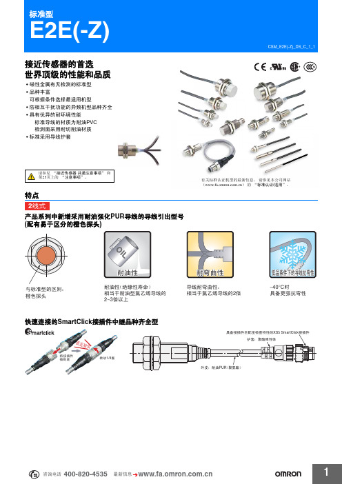
E2E(-Z)
会提示线圈断线等故障及检测不稳定状态的自诊断功能输出型品种齐全
• 有助于实现预防性维护,防止生产线停转。
简化配线过程,降低资源使用,有效减小功耗,助力环保事业
• 配线作业时间及铜线使用量仅为3线式的三分之二。 • 电流消耗量大幅降低至10%以下。 (直流2线式与直流3线式相比)
2mm
导线引出型 (2m)
PVC (耐油) - - PUR (耐油强化) PVC (耐油) PUR (耐油强化)
M12 接插件型 M8 接插件型 M12 SmartClick 接插件中继型 (0.3m)
导线引出型 (2m) M12
3mm
M12 接插件型
PVC (耐油) -
M12 标准接插件中继 型 (0.3m)
3㒓ᓣ
产品系列中包含小口径型号 (3、 4、 5.4、 M5)
• 所有小口径型号均采用屏蔽结构。即使将传感器安装在狭小区域或嵌入金属中,仍然具有较高的工作稳定性。 • 配有明亮醒目的指示灯,轻松查看安装环境。
宽广的使用环境温度 -40~+85C (M8~M30型)
• 小口径型号同样具备宽广的使用温度范围:-25C~+70C • 适用于光电传感器难以胜任的低温和高温应用场合。
ϡᯧফ਼ೈ䞥ሲⱘᕅડ
ሣ㬑ൟ
㓈ᡸֱݏᗻ
ޣᇥᑧᄬ
NPNǃ PNP݅⫼
Ⳉ⌕2㒓ᓣ E2E-XƶDƶ ѸⳈ⌕ϸ⫼2㒓ᓣ E2E-XƶT1 ᦦӊЁ㒻SmartClickൟ E2E-XƶDƶ-M1TGJ-(U) ᦦӊЁ㒻ൟ E2E-XƶD1-M1(G)J-(T) ᦦӊൟ E2E-XƶDƶ-M1(G) E2E-XƶEƶ-M1 E2E-XƶYƶ-M1
欧姆龙接近开关E2E-X4MD1

欧姆龙接近开关E2E-X4MD1简介欧姆龙接近开关E2E-X4MD1是一种非接触式传感器,用于检测物体是否接近开关,通常用于自动化控制系统。
该开关采用磁感应原理工作,可以识别铁质和非铁质材料。
E2E-X4MD1是欧姆龙公司生产的一款具有高可靠性和长寿命的接近开关,广泛应用于工业自动化和机器人控制系统。
构成E2E-X4MD1接近开关由四个主要部分组成:1.感应面:用于检测物体是否接近开关,通常为金属材料。
2.感应元件:用于转换感应面的信号为电信号,通常为磁敏元件。
3.电路板:用于处理并放大电信号,通常为数字电路。
4.脚座:用于连接电源和控制器,通常为插头或接线端子。
工作原理E2E-X4MD1接近开关采用磁感应原理工作。
当感应面靠近磁敏元件时,感应面产生的磁场会影响磁敏元件的磁场,从而引起感应元件中感应电动势的变化。
感应元件将变化的电信号输出到电路板上,经过电路板的处理和放大,然后输出到控制器上。
技术参数E2E-X4MD1接近开关的技术参数如下:•检测距离:4mm•接头类型:M12插座•工作电压范围:10~30VDC•感应物体:铁质或非铁质材料•最大开关频率:1000Hz•最大开关电流:200mA•最大负载电压:30VDC•工作温度范围:-25℃~70℃•保护等级:IP67应用场景E2E-X4MD1接近开关广泛应用于以下领域:1.工业自动化控制系统:可用于自动控制输送带或流水线的开关,以检测物体的位置和传送状态。
2.机器人控制系统:可用于检测机器人的位置和操作状态,以调整机器人的动作和速度。
3.食品加工和制药行业:可用于检测食品或药品的位置和状态,以保证产品质量和安全性。
4.包装行业:可用于自动控制包装机械,以准确地控制包装材料和产品的位置和数量。
总结E2E-X4MD1接近开关是欧姆龙公司生产的一款高可靠性和长寿命的非接触式传感器,采用磁感应原理工作,可以检测铁质和非铁质材料的位置和状态。
该接近开关广泛应用于工业自动化和机器人控制系统,以及食品加工、制药和包装行业。
欧姆龙接近开关主要是E2E

欧姆龙接近开关:主要是E2E本月400技术热线TOP 10问题1、 Q:接近传感器的直流二线式和直流三线式之间的区别是什么? A:直流二线式,输出NPN或PNP都可以接,但是有残电压;直流三线式,输出分NPN或PNP,但是无残电压。
2、 Q:接近传感器非屏蔽型和屏蔽型的区别是什么?A:屏蔽型:检测线圈的侧面用金属覆盖,磁通集中在传感器的前部作。
非屏蔽型:检测线圈的侧面未被金属覆盖,磁通广泛发生在传感器的前部。
屏蔽型相对于非屏蔽型检测距离短,不易受周围金属(磁性体)影响。
3、 Q:E2E停产替代A:E2E所有型号都用E2E-Z替代。
-Z产品为中国生产,专供中国大陆市场销售,不带-Z的中国和日本都有生产,两者在规格、使用上完全相同。
4、 Q:E2E-X_D_,没有输出?A:直流二线式,没有串联负载5、 Q: TL-Q/-N带-Z的区别?A:-Z输出多了二极管,输出容量更大6、 Q:接近传感器选型要素有哪些?A:①检测类型:放大器内藏型、放大器分离型②外形:圆形、方形、凹槽型③检测距离:以mm为单位④检测物体:铁、钢、铜、铝、塑料、水、纸等⑤工作电源:直流、交流、交直流通用⑥输出形态:常开(NO)、常闭(NC)⑦输出方式:两线式、三线式(NPN、PNP)⑧屏蔽、非屏蔽⑨导线引出型、接插件式、接插件中继式⑩应答频率:一秒钟能检测几个物体(详见产品样本性能表中说明)其他:工作环境、开关容量、外壳材质、附件7、 Q:E2E系列型号最后-M1,-M1G,M1GJ,M1J的含义?A:-M1,-M1G表示接插件型,-M1J,-M1GJ表示接插件中继型;接插件型是在传感器尾部有一个插口可以连接插件;接插件中继型的传感器尾部有一段导线连了一个8、 Q:霍尔开关是否有,检测磁性物体。
A:没有,推荐静电容型E2K系列,但是检测距离不定9、 Q:E2E的动作状态NO/NC是什么意思?A:NO是常开,没有检测到物体时接点断开,检测到物体时接点闭合;NC是常闭,没有检测到物体时接点闭合,检测到物体时接点断开。
E2E微型靠近传感器产品参数说明书

1E2E High performance in small sizes•pre-wired and M8 connector models •3mm, 4mm, 5.4mm and M5 sizes •response frequency up to 3kHzOrdering InformationSizeSensing Distance Connection Housing Material OutputOperation mode NO Operation mode NC dia 3mm shielded0.6mm pre-wired stainless steelPNP E2E-CR6B1E2E-CR6B2NPN E2E-CR6C1E2E-CR6C2dia 4mm0.8mmpre-wired PNP E2E-CR8B1E2E-CR8B2NPN E2E-CR8C1E2E-CR8C2M8 connectorPNP E2E-CR8B1-M5E2E-CR8B2-M5NPN E2E-CR8C1-M5E2E-CR8C2-M5M51mmpre-wired brassPNP E2E-X1B1E2E-X1B2NPN E2E-X1C1E2E-X1C2M8 connectorPNP E2E-X1B1-M5E2E-X1B2-M5NPN E2E-X1C1-M5E2E-X1C2-M5dia 5.4mmpre-wiredPNP E2E-C1B1E2E-C1B2NPNE2E-C1C1E2E-C1C22Inductive SensorsSpecificationsE2E-C @C @/B @, E2E-X1C @/B @ DC 3-wire ModelsNote:The response speed is an average value. Measurement conditions are as follows: standard sensing object, a distance of twice the standardsensing object, and a set distance of half the sensing distance.Size 3 dia.4 dia.M55.4 dia.TypeShieldedItemE2E-CR6C @/B @E2E-CR8C @/B @E2E-X1C @/B @E2E-C1C @/B @Sensing distance 0.6mm ±15%0.8 mm ±15% 1 mm ±15%Set distance 0 to 0.4mm0 to 0.5 mm0 to 0.7 mmDifferential travel 15% max. of sensing distanceSensing objectFerrous metal (The sensing distance decreases with non-ferrous metal, refer to Engineering Data .)Standard sensing object Iron: 3x3x1 mm Iron: 5x5x1mm Response speed (See note.)2kHz3kHzPower supply voltage (operating voltage range)12 to 24 VDC (10 to 30 VDC), ripple (p-p): 10% max.Current consumption 10mA max.17 mA max.Control output Load currentOpen-collector output, 80mA max.(at 30VDC max.)Open-collector output 100 mA max. (at 30 VDC max.)Residual voltage1 VDC max.(Load current: 80mA, Cable length: 2m)2 VDC max. (Load current: 100 mA , Cable length: 2 m)IndicatorOperation indicator (red LED)Operation mode (with sensing object approaching)C1/-B1 Models:NO C2/-B2 Models:NCFor details, refer to Timing Charts .Protection circuits Power supply reverse polarity protection, surge suppressor Ambient temperature Operating/Storage: –25°C to 70°C (with no icing or condensation)Ambient humidity Operating/Storage: 35% to 95%Temperature influence ±15% max. of sensing distance at 23︒C in the temperature range of –25°C to 70°C Voltage influence ±5% max. of sensing distance in the rated voltage range ±10%±2.5% max. of sensing distance in the rated voltage range ±15%Insulation resistance 50 M Ω min. (at 500 VDC) between current-carrying parts and case Dielectric strength 500 VAC at 50/60 Hz for 1 min between current-carrying parts and case Vibration resistance 10 to 55 Hz, 1.5-mm double amplitude for 2 hours each in X, Y, and Z directions Shock resistance 500 m/s 2 10 times each in X, Y, and Z directions Degree of protection IEC 60529: IP66IEC 60529 IP67 (Pre-wired models: JEM standard IP67g (waterproof, oil-proof))Connection method Pre-wired models (standard length 2 m), connector models Weight(packed state)Pre-wired models Approx. 60 g Connector models —Approx. 12 gApprox. 15 g —MaterialCaseStainless steel (SUS303)Brass-nickel platedSensing surface Heat-resistant ABS Clamping nuts Brass-nickel plated Toothed washerIron-zinc plated AccessoriesInstruction manual3E2E Output Circuits and Timing ChartsOutput CircuitsDC 3-wire ModelsTiming ChartsPin ArrangementE2E-CR8C @/CR8B @/X1C@/X1B@-M5 DC 3-wire ModelsIronCopperS t a inle ss s teel(S U S304) Br ass Al u min u m t = 1 mmIron S t a inle ss s teel (S U S304)Br assAl u min u mt = 1 mmS e n s i n g d i s t a n c e (m m )S ide length of s en s ing o b ject d (mm)S ide length of s en s ing o b ject d (mm)NPN Open-collector OutputBlue 3LoadBlack 4Brown 10 V100 ΩBlue 3LoadBlack 4Brown 10 VOutput100 ΩProximity sensor main circuitProximity sensor main circuit* Pin 4 is an NO contact, and pin 2 is an NC contact.* Pin 4 is an NO contact, and pin 2 is an NC contact.E2E-C/X @C @/B @NPN/PNP Open-collector OutputSensing object Control outputY es NoON OFF Operation indicator (red)ON OFF4Inductive SensorsPrecautionsMountingDo not tighten the nut with excessive force. A washer must be used with the nut.Note:The table below shows the tightening torques for part A andpart B nuts. In the previous examples, the nut is on the sensor head side (part B) and hence the tightening torque for part B applies. If this nut is in part A, the tightening torque for part A applies instead.Refer to the following to mount the E2E-CR8 and E2E-C1non-screw models.Tighten the screw to a torque of 0.2 N·m maximum to secure the E2E-CR8 and a torque of 0.4 N·m maximum to secure the E2E-C1.Effects of Surrounding MetalWhen mounting the E2E within a metal panel, ensure that the clearances given in the following table are maintained. Failure to maintain these distances may cause deterioration in the performance of the sensor.Mutual InterferenceWhen installing two or more Sensors face to face or side by side, ensure that the minimum distances given in the following table are maintained.Note:Values in parentheses apply to Sensors operating at different frequen-cies.ModelPart APart B LengthTorqueTorqueM51 N·mModel Item 3 dia. 4 dia.M5 5.4 dia.E2E-X @C @E2E-X @B @E2E-C @C @E2E-C @B @DC 3-wireShielded l 0 mm 0 mm 0 mm 0 mm d 3 mm 4 mm 5 mm 5.4 mm D 0 mm 0 mm 0 mm 0 mm m2 mm 2.4 mm3 mm3 mm n6 mm6 mm8 mm8 mmShielded Model Unshielded Model Part B Part APart B Part A8 to 21 mmM3 holeNo screw is provided with the E2E-CR8 or E2E-C1.d dia.Model Item 3 dia. 4 dia.M5 5.4 dia.E2E-X @B @E2E-X @C @E2E-C @B @E2E-C @C @DC 3-wireShielded A 20 mmB 15 mm5E2E Precautions for Safe UseThe colors in parentheses are previous wire colors.Precautions for Correct UseInstallation Power Reset TimeThe Proximity Sensor is ready to operate within 100 ms after power is supplied. If power supplies are connected to the Proximity Sensor and load respectively, be sure to supply power to the Proximity Sensor be-fore supplying power to the load.Power OFFThe Proximity Sensor may output a pulse signal when it is turned OFF. Therefore, it is recommended to turn OFF the load before turn-ing OFF the Proximity Sensor.Power Supply TransformerWhen using a DC power supply, make sure that the DC power supply has an insulated transformer. Do not use a DC power supply with an auto-transformer.Sensing ObjectMetal Coating:The sensing distances of the Proximity Sensor vary with the metal coating on sensing objects.WiringHigh-tension LinesWiring through Metal ConduitIf there is a power or high-tension line near the cable of the Proximity Sensor, wire the cable through an independent metal conduit to pre-vent against Proximity Sensor damage or malfunctioning.Cable Tractive ForceDo not pull on cables with tractive forces exceeding the following.MountingThe Proximity Sensor must not be subjected to excessive shock with a hammer when it is installed, otherwise the Proximity Sensor may be damaged or lose its water-resistivity.Environment Water ResistivityDo not use the Proximity Sensor underwater, outdoors, or in the rain.DC 3-wire ModelsSensorBrownBlackBlueLoadIncorrectDC 3-wire Models (NPN output)SensorBrownBlackBlueLoad(Load short- circuit)DC 3-wire Models (NPN output)SensorBrownBlueLoadBlackSensorBrownBlackLoadBlueIncorrectDC 3-wire ModelsSensorBrownBlueLoadIncorrectDiameterTractive force4 dia. max.30 N max.4 dia. min.50 N max.6Inductive SensorsOperating EnvironmentBe sure to use the Proximity Sensor within its operating ambient tem-perature range and do not use the Proximity Sensor outdoors so that its reliability and life expectancy can be maintained. Although the Proximity Sensor is water resistive, a cover to protect the ProximitySensor from water or water soluble machining oil is recommended so that its reliability and life expectancy can be maintained.Do not use the Proximity Sensor in an environment with chemical gas (e.g., strong alkaline or acid gasses including nitric, chromic, and con-centrated sulfuric acid gases).Connection to a PLC Required ConditionsConnection to a PLC is possible if the specifications of the PLC and the Proximity Sensor satisfy the following conditions. (The meanings of the symbols are given below.)1.The ON voltage of the PLC and the residual voltage of the Prox-imity Sensor must satisfy the following.V ON ≤ V CC – V R2.The OFF current of the PLC and the leakage current of the Prox-imity Sensor must satisfy the following.I OFF ≥ I leak(If the OFF current is not listed in the specifications, take it to be 1.3 mA.)3.The ON current of the PLC and the control output (I OUT ) of the Proximity Sensor must satisfy the following.I OUT(min) ≤ I ON ≤ I OUT(max)The ON current of the PLC will vary, however, with the power sup-ply voltage and the input impedance used as shown in the follow-ing equation.I ON = (V CC – V R – )/R INExampleIn this example, the above conditions are checked for when the PLC model is the C200H-ID212, the Proximity Sensor model is the E2E-X7D1-N, and the power supply voltage is 24 V .1.V ON (14.4 V) ≤ V CC (20.4 V) – V R (3 V) = 17.4 V: OK 2.I OFF (1.3 mA) ≥ I leak (0.8 mA): OK3.I ON = [V CC (20.4 V) – V R (3 V) – ≈4.5 mA Therefore,I OUT(min) (3 mA) ≤ I ON (4.5 mA): OKV ON : ON voltage of PLC (14.4 V)I ON : ON current of PLC (typ. 7 mA)I OFF : OFF current of PLC (1.3 mA)R IN : Input impedance of PLC (3 k Ω)V R : Output residual voltage of Proximity Sensor (3 V)I leak : Leakage current of Proximity Sensor (0.8 mA)I OUT : Control output of Proximity Sensor (3 to 100 mA)V CC : Power supply voltage (PLC: 20.4 to 26.4 V)Values in parentheses are for the following PLC model and Proximity Sensor model.PLC: C200H-ID212Proximity Sensor: E2E-X7D1-NNote:please refer to complete E2E/E2E2 datasheet for details on E2E-X7D1-NV PC V PC (4 V)]/R IN (3 k Ω)V PC : Internal residual voltage of PLC (4 V)Model Connection type Method DescriptionDC 3-wireAND (serial connection)The Sensors connected together must satisfy the following conditions.i L + (N –1) x i ≤ Upper-limit of control output of each SensorV S – N x V R ≥ Load operating voltage N: No. of SensorsV R : Residual voltage of each Sensor V S : Supply voltagei: Current consumption of the Sensor i L : Load currentIf the MY Relay, which operates at 24 VDC, is used as a load for example, a maximum of two Proximity Sensors can be connected to the load.LoadCorrect7E2E DimensionsNote:All units are in millimeters unless otherwise indicated.Pre-wired Models (Shielded)Dimensions 3 dia.4 dia.M55.4 dia.F (mm)3.3 dia.4.2 dia.5.5 dia.5.7 dia.+0.30+0.50+0.50+0.50ALL DIMENSIONS SHOWN ARE IN MILLIMETERS.To convert millimeters into inches, multiply by 0.03937. T o convert grams into ounces, multiply by 0.03527.Terms and Conditions of SaleCertain Precautions on Specifications and UseOMRON CANADA, INC. • HEAD OFFICEToronto, ON, Canada • 416.286.6465 • 866.986.6766 • OMRON ELECTRONICS DE MEXICO • HEAD OFFICEMéxico DF • 52.55.59.01.43.00 • 001.800.556.6766 •************** OMRON ELECTRONICS DE MEXICO • SALES OFFICEApodaca, N.L. • 52.81.11.56.99.20 • 001.800.556.6766 •************** OMRON ELETRÔNICA DO BRASIL LTDA • HEAD OFFICESão Paulo, SP, Brasil • 55.11.2101.6300 • .br OMRON ARGENTINA • SALES OFFICE Cono Sur • 54.11.4783.5300 OMRON CHILE • SALES OFFICE Santiago • 56.9.9917.3920 OTHER OMRON LATIN AMERICA SALES 54.11.4783.5300OMRON INDUSTRIAL AUTOMATION • THE AMERICAS HEADQUARTERSSchaumburg, IL USA • 847.843.7900 • 800.556.6766 • OMRON EUROpE B.V. • Wegalaan 67-69, NL-2132 JD, Hoofddorp, The Netherlands. •Tel: +31 (0) 23 568 13 00Fax: +31 (0) 23 568 13 88 •www.industrial.omron.euCat. No. D11E-EN-02A01/12 Note: Specifications are subject to change. © 2012 Omron Electronics LLC Printed in U.S.A.。
欧姆龙接近传感器常见问题

欧姆龙接近传感器常见问题接近开关和OMRON的PLC怎么接线?:直流二线型:褐色线接PLC输入点,PLC的com点接到电源正极,电源负极接到蓝色线。
NPN型:褐色接电源正,蓝色接电源负,黑色线接到PLC输入点,PLC的com点接到电源正。
NPN是漏型,检测到物体时输出低电平信号。
PNP型:褐色接电源正,蓝色接电源负,黑色线接到PLC输入点,PLC的com点接到电源负。
PNP是源型,检测到物体时输出高电平信号。
接近传感器可以检测哪些物体?:接近传感器的被测物体分为磁性金属(如铁、镍等),非磁性金属(如黄铜、铝等)和非金属(如塑料、玻璃、水等)。
接近传感器按照检测原理分为电感型和电容型。
电感型接近传感器(如E2E)只能检测金属,不能检测非金属。
电容型接近传感器(如E2K)可以检测金属和非金属。
以上两种类型的接近传感器根据被测物体材质的不同,检测距离也不同E2E-□□□和E2E-□□□-N的区别是什么?:-N有新版本的意思,并且在具体的规格、性能上与没有-N的产品有区别。
E2E-X2D1的外径是M12,响应频率800Hz。
E2E-X2D1-N的外径是M8,响应频率是1500Hz。
传感器的长度也不完全一样,除这些外的其余参数相同。
接近传感器有误动作现象,如何解决?:请按照以下步骤排故:①稳定电源给接近传感器单独供电;②响应频率在额定范围内;③物体检测过程中有抖动,导致超出检测区域;④多个探头紧密安装互相干扰;⑤传感器探头周围的检测区域内有其他被测物体;⑥接近传感器的周围有大功率设备,有电气干扰。
接近传感器检测到被测物体后续设备都不动作,为什么?:接近传感器分两种,电感型和静电容型,分别按照以下步骤排故。
电感型:①供电电压要在额定范围内;②被测物体是金属,大小尺寸足以让传感器可以检测到;③被测物体在传感器检测的有效范围内;④传感器是常开还是常闭;⑤和后续设备接线方式正确,信号匹配;⑥接近传感器的开关容量足够驱动后续设备。
欧姆龙接近开关说明书
Ẕ⌟⠽ԧⱘ䖍䭓d(mm)
E2K-X8M
䎱 行 10 X嗻 嗼 mm 8
ƶ50 t
X 6
4
2
0
5
10
ഄ䞥ሲ
䴲ഄ䞥ሲ ⦏⩗ 㣃䜮˄ᷥ㛖˅
ϭ⛃䝌˄ᷥ㛖˅
15
20
25
Ẕ⌟⠽ԧⱘ䖍䭓t(mm)
E2K-X15M
䎱 行 25 X嗻 嗼 mm 20
ƶd t=3mm
X
15
10
5
ഄ䞥ሲ
䴲ഄ䞥ሲ
⦏⩗ 㣃䜮˄ᷥ㛖˅ ϭ⛃䝌˄ᷥ㛖˅
1
E2K-C
⦏⩗ 㣃䜮˄ᷥ㛖˅
E2K-X E2K-F
0
5
10
15
20
25
Ẕ⌟⠽ԧⱘ䖍䭓t(mm)
E2K-L
E2KQ-X
E2J
E2K-X8M
䎱 行 10
X嗻 嗼 mm
8
ƶd t=3mm
X
ഄ䞥ሲ
6 䴲ഄ䞥ሲ
4
⦏⩗ 2
㣃䜮˄ᷥ㛖˅
ϭ⛃䝌˄ᷥ㛖˅
0
10 20 30 40 50 60 70
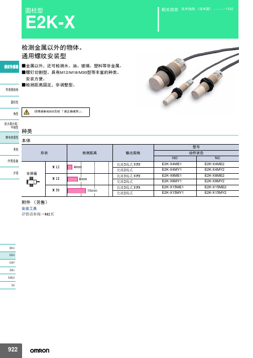
圆柱型
E2K-X
检测金属以外的物体。 通用螺纹安装型
䖥Ӵᛳ఼ ■金属以外,还可检测水、油、玻璃、塑料等非金属。 ■螺钉切割型。具有M12/M18/M30型等丰富的种类。 安装方便。 ■检测距离固定,非调整型。
Ӵᛳ఼ᣛफ
᷅ൟ
详情请参阅926页的 「请正确使用」。
㾦ൟ
ᬒ఼ߚ行
Ё㒻ൟ 种类
䴭⬉ᆍ䞣ൟ 本体
ˆ2. Eൟ˖Ẕ⌟ᰒ冫♃˄㑶˅ Yൟ˖ࡼᰒ冫♃˄㑶˅
䖥Ӵᛳ఼
Ӵᛳ఼ᣛफ ᷅ൟ 㾦ൟ ᬒ఼ߚ行 Ё㒻ൟ 䴭⬉ᆍ䞣ൟ ݊Ҫ ೈ䆒 ҟ㒡
欧姆龙接近开关各类不同型号信息

欧姆龙接近开关各类不同型号信息
*直流开关部的响应频率为平均值。
测定条件为:有标准检测物体时,检测物体的间隔为标准检测物体的2倍,设定距离为检测距离的1/2。
直流3线式
*直流开关部的响应频率为平均值。
测定条件为,有标准检测物体时,检测体的间隔为标准检测物体的2倍,设定距离为检测距离的1/2。
直流3线式/交流2线式
*1. 直流开关部的响应频率为平均值。
测定条件为:有标准检测物体时,检测体的间隔和为检测物体的2倍,设定距离为检测距离的1/2。
*2. E型(直流开关型)可用DC24V±10%(平均值)的全波整流电源。
更多欧姆龙接近开关知识,详情可参考:。
打号机使用手册

唐山不锈钢有限责任公司热轧生产线打号机使用手册(机械部分)目录设备的预防处理第一章介绍1.1 打号机的概要1.2 结构配置第二章描述基本2.1 (提供打号的位置)2.2 打号2.3 公用2.4 设备说明书2.4.1 打号前端的机械装置2.4.2 打号前端部分2.5 漆料供给第三章拆卸,装配和维修3.1 打号机的维修操作3.2 急停检测(抱闸打开说明)3.3 打号机前进机械装置的油润滑3.3.1 前进机械装置润滑3.3.2 前进机械装置限位开关的更换3.3.3 上升机械装置的润滑3.3.4 升降机械装置限位开关的更换3.3.5滑行机械装置润滑3.3.6 滑行限位开关的更换3.4 打号机头部的维修3.4.1 打开关闭水冷却和热保护罩3.4.2 倾斜机械部分限位开关的更换3.4.3 倾斜顶部调速带限位开关的更换3.4.4 板卷检测汽缸传感器的更换3.4.5板卷检测器位置的调整第四章维修和检查4.1 周期性检查4.2 压力设定4.3加油和润滑第五章发现并修理故障5.1 机械常见故障第一章介绍1.1打号机的概要这种打号机从主机接收控制数字和其它类型的数字,自动的将这些信息标记在板卷的规定直径的外部表面上!这个设备在板卷停止移动的时候开始工作,打号前端从固定位置移动到要被打号板卷的正确位置,然后打号机里面7个点提供所需打号的形状,目的是为了完成打号。
这种打印机能在板卷的表面打10字*4行!此类打号机可以通过一个主机或者安装在操作室的触摸操作面板来完成打号。
可以实现热打号和冷打号,为了防止油漆管道和喷嘴堵塞,使用的是具有热抵抗力的油漆!1.2结构配置1)控制面板控制面板用来控制全部的打号机系统,由一些必要的顺控设备,变频器,继电器,还有其它类似的控制设备组成。
比如电源供给和断路器电源供给都准备了设备室,为了全自动的打号得以执行,连接了主机设备和移动设备的界面!更详细的信息,参考电气系统的使用说明!2)操作面板为了实现一个主要用来显示当前设备情况的触摸面板来执行设定各种操作模式,和手动的输入信息,提供了蜂鸣器和一些列的开关! 更详细的信息,参考电气系统的使用说明!3)本地操作面板(端子箱)主要用于执行维修操作和手动控制设备。
- 1、下载文档前请自行甄别文档内容的完整性,平台不提供额外的编辑、内容补充、找答案等附加服务。
- 2、"仅部分预览"的文档,不可在线预览部分如存在完整性等问题,可反馈申请退款(可完整预览的文档不适用该条件!)。
- 3、如文档侵犯您的权益,请联系客服反馈,我们会尽快为您处理(人工客服工作时间:9:00-18:30)。
OMRON接近开关e2e-x7d1-n
接近开关是一种无需与运动部件进行机械直接接触而可以操作的位置开关,当物体接近开关的感应面到动作距离时,不需要机械接触及施加任何压力即可使开关动作,从而驱动直流电器或给计算机(plc)装置提供控制指令。
接近开关是种开关型传感器(即无触点开关),它既有行程开关、微动开关的特性,同时具有传感性能,且动作可靠,性能稳定,频率响应快,应用寿命长,抗干扰能力强等、并具有防水、防震、耐腐蚀等特点。
产品有电感式、电容式、霍尔式、交、直流型。
接近开关又称无触点接近开关,是理想的电子开关量传感器。
当金属检测体接近开关的感应区域,开关就能无接触,无压力、无火花、迅速发出电气指令,准确反应出运动机构的位置和行程,即使用于一般的行程控制,其定位精度、操作频率、使用寿命、安装调整的方便性和对恶劣环境的适用能力,是一般机械式行程开关所不能相比的。
它广泛地应用于机床、冶金、化工、轻纺和印刷等行业。
在自动控制系统中可作为限位、计数、定位控制和自动保护环节等。
OMRON接近开关e2e-x7d1-n。