吉利 GX7 德赛西威一体机 NAV623V说明书
可攜式投影機 V300X V260X V230X V260 V230 使用手冊说明书

型號
V300X/V260X/V230X/V260/V230
使用手冊
2011 年 1 月第一版
DLP 和 BrilliantColor 是 Texas Instruments (德州儀器有限公司)的商標。 IBM 爲 International Business Machines Corporation (國際商業機器公司)的商標或註冊商標。 Macintosh, Mac OS X 和 PowerBook 爲 Apple Inc. (蘋果公司)在美國和其他國家註冊的商標。 Microsoft、Windows、Windows Vista、Internet Explorer、 .NET Framework 和 PowerPoint 爲 Microsoft Corporation (微軟公司)在美國和/或其他國家的註冊商標或商標。 MicroSaver 爲 ACCO 品牌的一個分公司 Kensington Computer Products Group 的註冊商標。 Virtual Remote Tool (虛擬遙控工具)使用 WinI2C/DDC library, © Nicomsoft Ltd。 HDMI、HDMI 標誌和 High-Definition Multimedia Interface 爲 HDMI Licensing LLC.的商標或註冊商標。
切勿讓紙夾和紙屑等異物掉入投影機內。切勿試圖找回可能掉入投影機內的任何物品。切勿將鐵絲或者螺絲起子 等金屬物體插入投影機內。若發現有物體掉入投影機內部,須立即斷開電源,然後委託有維修資格的維修服務人 員取出物體。 切勿在投影機上面放置任何物體。 雷雨天不要觸摸電源插頭。此舉可能引起電擊或者火災。 投影機規定操作電源爲 200-240 伏特 50/60 赫茲交流電。在使用投影機之前,須確認所用電源是否符合本投影機 要求。 切勿在投影機啓動狀態下窺視鏡頭。此舉會導致眼睛嚴重受傷。
NAV Slim 可携式汽车导航系统 说明书

NAV Slim可攜式汽車導航系統使用手冊版本版本::1.0版2008年九月註冊資訊HOLUX 和GPSmile 是HOLUX Technology, Inc.的商標。
所有其他商標屬於各註冊公司。
註若修改本手冊的內容,恕不另行通知。
本產品的適當操作溫度範圍在0℃到40℃之間。
在溫度超過45℃的環境中操作或充電可能導致系統無法作用。
但這是正常現象。
請勿在極端溫度的環境中操作本產品。
安全注意事項•請使用本產品包裝內隨附的電源轉換器,如果使用其他電源轉換器可能造成故障並產生危險。
•本機僅能搭配隨附的電池使用。
•關於電源轉換器:1. 不可在潮溼環境中使用電源轉換器。
手腳潮濕時,請勿碰觸電源轉換器。
2. 請確定在通風良好的區域使用電源轉換器。
不可讓紙張或其他物品覆蓋電源轉換器,這樣會影響它的冷卻。
電源轉換器在袋子內時,請勿使用它。
3. 不可嘗試維修本裝置。
如果本裝置損壞或在潮溼環境中,請立刻更換本裝置。
4. 本公司不建議從電腦上充電,因為電腦的電壓不足以供應本裝置所需的電壓。
電池第一次使用, 請充飽6小時以上, 以確保電池電量充足。
•關於電池1. 僅限使用原廠許可的充電器。
2. 本產品有內建的鋰電池。
要避免起火或皮膚燙傷,請勿拆解、刺穿、撞擊或將電池暴露在火源下。
如果丟入火源中,電池可能破裂、爆炸或釋放危險化學物質。
•重要指示1. 註:換用錯誤的電池可能產生爆炸。
請依照指示廢棄電池。
更換電池時,僅限使用原廠許可的電池。
2. 回收或廢棄電池時,必須依照法規。
3. 隨附的電池僅供本裝置使用。
保固聲明•本保固適用於Holux Technology Inc.製造和銷售的GPSmile62零件與服務。
涵蓋的區域範圍是台灣,保固日期是購買日期開始後的一年內(從銷售收據上的日期開始算起)。
在正常的使用下,HoluxTechnology提供免費的維修服務。
維修後,換下的零件屬於Holux Technology Inc.的財產。
西威变频器说明书
ARTDrive L转矩矢量电梯专用变频器使用手册SIEI 操作手册安全须知注意!根据EEC标准,只有在检查确认机器是那些符合89/392/EEC条款的设备制造的后,Avy及其附件才可以使用。
警告-电气击伤和烧伤危险当时用某些仪器比如示波器去测量带电设备时,示波器的外壳必须接地,而且应使用差分放大输入。
在选择探头,调试示波器时应格外小心这样才能安全读数。
为进行正确操作及调试,仔细阅读仪器生产厂家的操作手册。
警告-火灾和爆炸危险火灾和爆炸通常是由把传动装置放置在危险的地方,比如充满易燃易爆气体或粉尘的地方。
传动装置应放置在远离危险的地方,即便使用那些可以在以上地点使用的电机。
警告-扭伤不正确的抬举方式可能造成严重的人身伤害。
只有经过培训的专业人员使用适当的装置进行以上操作才是可取的。
注意!传动装置的接地和电机的接地必须遵守标准。
警告在装置上电前把盖板放回原处。
否则可能导致死亡或严重伤害。
警告变频调速传动装置是用于工业现场安装的电气设备。
在使用过程中装置的部分是带电的。
因此,电气安装和设备的开盖操作应由合格的专业人员进行。
电机和传动装置的不正确安装将导致人身和设备的损坏。
传动装置本身未带电机超速保护。
必须严格遵守手册中的指示和当地及国家的有关适用规定。
小心且勿连接到超过技术指标允许的电压波动范围的供电电源上。
如果过高的电压加在传动装置上将有可能损坏内部器件。
小心没有接地导线的条件下切勿操作传动装置。
电机外壳的接地应使用一根区别于其他接地柱的接地柱,这样可以避免噪声耦合。
接地连线的截面积应符合NEC标准或CEC标准。
连接可以采用UL列出的或CSA认可的闭环端子连接,这样可使用相应的序列规格。
施工时应使用生产厂家认可的压弯工具。
小心不要在传动装置端子或控制电路端子上进行绝缘测试。
小心因为环境温度将影响装置的寿命和可靠性,所以不要在超出允许温度的地点安放装置。
在104°F(40℃)或以下温度时请保持通风。
旺威汽车维修指南说明书
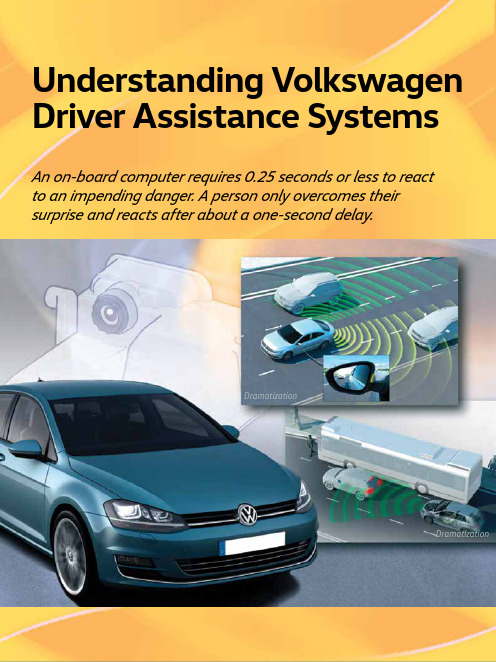
Understanding Volkswagen Driver Assistance SystemsAn on-board computer requires 0.25 seconds or less to reactto an impending danger. A person only overcomes theirsurprise and reacts after about a one-second delay.DramatizationDramatizationTechConnect Feature ArticleToday’s Volkswagen vehicles are available with many systems to enhance drivers’ experiences on the road. Some systems, like windshield wipers, are considered basic. Other systems, like ABS and traction control, are more advanced. But the next level of driver assistance features is here. An on-board computer requires 0.25 seconds or less to react to an impending danger. A person only overcomes their surprise and reacts after about a one-second delay.These advanced driver assistance systems can not only help alert the driver to an impending collision, but can also intervene to help avoid them altogether. Vehicles can brake to avoid a collision, and caneven park itself. It may seem like these features would be reserved for the most high-line cars in the fleet. But even the Golf and Golf SportWagen are available with many of the latest Volkswagen Driver Assistance systems.Before any type of testing or diagnosis of a system can occur, we must understand how each system works. This is vital when working on new available Driver Assistance systems. If we don’t understand how a system should work, we will not be able to properly identify an issue with a system. Where To StartWhen it comes to available Driver Assistance systems, the components vary from system to system. Let’s start by identifying each available feature.Automatic Post-Collision BrakingThe Automatic Post-Collision Braking system that results in an airbag deployment can automatically brake, slowing the vehicle down after an initial collision. This system is designed to lessen the severity of a secondary impact. Automatic Post-Collision Braking can slow the vehicle to a speed of 6 mph, and can be overridden by accelerating or hard braking. Available on:• 2015: Golf, GTI, Golf R, e-Golf, Golf SportWagen, Touareg• 2016: Golf, GTI, Golf R, e-Golf, Golf SportWagen, Jetta TSI, Jetta GLI/Hybrid, Beetle, BeetleConvertible, Touareg, PassatAdaptive Cruise Control (ACC)Adaptive Cruise Control functions very much like traditional vehicle cruise control. The speed is set by the driver, and the vehicle is designed to maintain that set speed. A vehicle equipped with ACC can also regulate speed based on the speed of other vehicles ahead. If a vehicle is detected ahead, the car will attempt to keep a consistent set distance from the other vehicle. Adaptive Cruise Control can accelerate on its own to the maximum set speed, and can brake automatically if the vehicle in front slows down. Available on:• 2015: Touareg• 2016: Golf, (manual transmission) GTI (manualtransmission), Golf R (manual transmission), Golf SportWagen (manual transmission) , Jetta TSI/TDI (automatic/DSG) Passat (automatic/DSG) Adaptive Cruise Control (ACC) with Follow to StopMuch like Adaptive Cruise Control, ACC with Follow to Stop can regulate the vehicle speed. In additionto speed and distance regulation, ACC with Followto Stop can bring the vehicle to a complete stop in normal traffic flow. Pressing the accelerator pedal, orusing the Resume function on the ACC control leverMid-Range Radar Sensor, 2015 Jetta The ACC system identifies the vehicles in front. V8 N1 Spring 201626Driver Assistance Systemson CC will resume ACC based on the distance from the vehicle in front.Available on:• 2015: Touareg• 2016: Golf, (automatic/DSG), GTI (DSG), Golf SportWagen (automatic/DSG), Touareg Sensors used:• Front Long-Range and Mid-Range RadarsForward Collision WarningVehicles with Forward Collision Warning can help to monitor the distance to traffic ahead. The system helps warn the driver of critical front-end collision situations. An audible alert and a visual warning are displayed in the MFI display.Available on:• 2015 Golf, GTI, Golf SportWagen, sensor is located below the front grill• 2015 Jetta, sensor is located behind the Volkswagen logo on grill• Also available on Passat, Touareg, and CC as a function of Front Assist Sensors used:• Front Radar Sensors• Long-Range and Mid-RangeAutonomous Emergency Braking (Front Assist)Autonomous Emergency Braking is a system that takes Forward Collision Warning a step further. It can apply the brakes automatically if the sensors detect a potential collision. This is done in two stages. Stage one is a short, jolting braking maneuver. If the driver fails to react to the first alert, Autonomous Emergency Braking can initiate an automatic braking maneuver. This can slow the vehicle down, increasing braking force. However, at speeds below 19 mph there is no warning jolt.Sensor locations:• Golf family: below front grill and also has a camera in front of the inside rear view mirror • Jetta/CC/Passat: behind Volkswagen logo on grill • Touareg: Adjacent to front fog lights, and camera in front of the interior rear-view mirror. Available On:• 2015: Touareg• 2016: Golf, GTI, Golf R, e-Golf, Golf SportWagen, Jetta TSI, CC VR6, Touareg, PassatBlind Spot MonitorUsing two radars at the rear of the vehicle, Blind Spot Monitor can alert drivers to vehicles in adjacent lanes. The two sensors constantly scan for traffic in the vehicle’s blind spot. The system can scan a range of approximately 65 feet.LEDs in the side mirrors, or on the mirror housing in the Touareg, alert the driver to any vehicle in the blind spot. If the driver uses the turn signals, the LEDs flash to warn of a dangerous situation. Available On:• 2015: Jetta, Beetle, Beetle Convertible• 2016: Golf, GTI, Golf R, Golf SportWagen, Jetta, Beetle, Beetle Convertible, Passat Sensors used:• Rear RadarsSide Assist (Lane Change Assist)Available only on the 2015 and 2016 Touareg, Side Assist can aid the driver by monitoring traffic behind and next to the vehicle. The rear radarmonitors up to a distance of about 230 feet. A series of four indicator lights warn the driver of traffic. As a vehicle gets closer to the Touareg, more lights will illuminate. When an approaching vehicle is very close, all four indicators will be lit.Rear Traffic AlertWhether it’s a moving object like a passing car, or a stationary object like a trash can, Rear Traffic Alert can warn of objects crossing directly behind the vehicle. Not only that, but radar-based sensors are used to help warn of vehicles approaching from the side when backing up. Rear Traffic Alert can even apply the brakes when the vehicle is in reverse when the radar sensors detect a potential collision with a vehicle approaching from the side, and there is also a warning sound and, if equipped with ParkPilot, a visual warning as well.Available On:• 2015: Jetta, Beetle, Beetle Convertible• 2016: Golf, GTI, Golf R, Golf SportWagen, Jetta, Beetle, Beetle Convertible, Passat Sensors used:• Rear Radar SensorsLane Departure Warning (Lane Assist)While the system will not relieve the driver from any responsibility, Lane Assist can steer to keep the vehicle within the lanes and provide a visual alert to the driver if the vehicle attempts to change lanes27Volkswagen TechConnectV8 N1 Spring 2016without the use of a turn signal. The front camera on the windshield identifies lane markings on the road. It processes the signal to determine if the vehicle is staying in the lane or not. Lane Assist can be overridden by the driver at any time. Using the turn signal indicator will also switch Lane Assist to passive mode.Lane Departure Warning (Lane Assist) — TouaregThe Lane Departure Warning system on the Touareg functions differently than on other Volkswagen models. The Touareg system will not provide active steering intervention. If lane departure is detected, the system can send a signal to vibrate the steering wheel to gain the driver’s attention. There is also a visual indication in the multifunction display.Lane Assist — Golf, GTI, Golf R, Golf SportWagen, CC VR6, PassatOn these models Lane Departure Warning can provide active countersteer measures to help keep the vehicle in the lane. If the vehicle crosses the lane without using a turn signal, visual warning are given asking the driver to take over steering.Sensors used:• Multifunction CameraPark Distance Warning System (ParkPilot)Volkswagen’s ParkPilot uses ultrasonic sensors that can measure the distance from the car’s front and rear bumpers to objects near the car. An acoustic and/or visual signal can alert the driver if the vehicle gets too close to an object.Available On:• 2015: Golf, GTI, Golf R, e-Golf, Golf SportWagen, Jetta Hybrid, EOS, CC, Touareg• 2016: Golf, GTI, Golf R, e-Golf, Golf SportWagen, Jetta, EOS, CC VR6, Touareg, PassatSensors used:• Ultrasonic SensorsParking Steering Assistant (Park Assist)Available for the first time on some 2016 models, Park Assist can help steer the car into parallel and perpendicular parking spots in reverse. The Park Assist button is pressed once for parallel parking and twice for perpendicular parking. The driver only needs to operate the accelerator pedal and brake once the gear is selected. Park Assist canautomatically steer the vehicle into the parking spot. While traveling below 25 mph, Park Assist system can scan both left-hand and right-hand sides of the road for parking spots. The driver will stipulate which side of the road he wishes to park on by activating the turn signal. Once a parking spot is identified, the driver will need to shift into reverse and operate the accelerator and brake pedal. The Multi Function Indicator (MFI) display will advise the driver when to switch from reverse to forward, and back into reverse gear.The system can be deactivated at any time by:• Turning the steering wheel • Increasing speed above 4 mph • Pulling out of a parking space• Pressing the Park Assist button onceAvailable on:• 2016: Golf, GTI, Golf SportWagen, Passat, e-Golf Sensors used:• Ultrasonic SensorArea ViewArea View is a Touareg-only feature. Area View is a 360-degree surrounding monitoring system. It uses four cameras to transmit images of the complete area around the vehicle, into the central display on the center console. The system can create an overall view of the surrounding area from the perspective of avirtual overhead camera. This can be especially helpful for customers aligning their Touareg with a trailer. Available on:• 2015, 2016 TouaregSensor OverviewKnowing the location and function of the various sensors and cameras used in Volkswagen’s Driver Assist systems is very important. Identifying issues with Driver Assist systems may be as simple as a visual inspection. If the vehicle, for example, has acracked windshield near the front camera, bumpersTouareg camera will monitor approximately 260 ft (80 m) ahead28Driver Assistance Systemsdamaged, or radars obscured, proper performance may be affected. This can cause erratic behavior in many Driver Assistance systems.Front SensorsFor 2016, many Volkswagen vehicles have a single mid- range radar sensor. The Touareg has a different system with two long-range radar sensors . These radar sensors are used for the Adaptive Cruise Control (ACC) and/or Front Assist functions.Mid-Range SensorsThe MRR Distance Regulation Control Module J428 is located at the front center of the vehicle, either behind the VW emblem, or below the VW emblem in the center of the bumper cover.This is a radar sensor that helps detect vehicles and obstructions in front of the vehicle. It is used differently for different systems. This is also the rear sensor for the RTA and other functions that are located in the bumper corners. It has the following features: • It has a frequency of 77 GHz• To help keep ice off at lower temperatures, the MRR has a heater• Range: Up to 525 ft. (160 m)• Speed: 0 - 100 mph (0 - 160 km/h) The MRR sensor is not standard equipment. However, it is used on many 2015 and newer vehicles, with the exception of the Touareg.Long-Range Radar (LRR) SensorsThe Touareg uses two long-range radar sensors located next to the fog lamps. They are 3rdGeneration radar sensors with the following features: • Each sensor has four radar antenna units • They have a frequency of 77 GHz• To help keep ice off at lower temperatures, the LRR has a heated lens• Range: Up to 656 ft. (200 m)• Speed: 0 - 130 mph (0 - 210 km/h)This generation of dual radar sensors allows the entire width of a three-lane road to be scanned, from as far as 99 feet (30 m) away.Touareg Driver Assistance Front Camera.29Volkswagen TechConnectV8 N1 Spring 2016The Distance Regulation Control Module J428 is the master, and it is located inboard of the right fog lamp. Distance Regulation Control Module 2 J850 is the slave and is located inboard of the left fog lamp.Multifunctional Front CameraThis camera can detect vehicles that may also be visible to the front radar system by using an actual camera to monitor the area in front of the vehicle. It confirms that a vehicle is there through sensor fusion to improve performance in critical situations.The camera monitors the area in front of the vehicle when stationary, preparing for a restart of the ACC system. It can also support front assist features, as well as detect lane markings for lane departure warning (Lane Assist).Front Camera (except Touareg)The front camera is located on the inside of the windshield, in front of the rear view mirror. Driver Assistance Systems Front Camera R242 provides image information to the following driver assist systems including Lane Departure Warning (Lane Assist) and ACC with Front Assist.The front camera can detect a variety of objects, such as vehicles and lane markers. The position of any detected object is captured by the camera, then transferred to the Distance Regulation Control Module J428. J428 compares the camera object data with the data of objects detected and mapped using radar.Front camera R242 also has a built in heating element. The Window Defogger for Front Sensor System Z113 prevents the part of the windscreen directly in front of the camera from misting up or icing over.Camera Control Module J852 and camera R242 are incorporated into the same module. J852 sends information via the extended CAN bus to be used by the lane departure warning system.Front Camera — TouaregThe front camera for the Touareg is similar to other front camera systems. It is integrated into the mirror base and has the following features:• It is a color camera with 1024 x 512 resolution • The range can be up to 2624 ft. (800 m)• The horizontal opening angle is 42 degrees and the vertical angle is 21 degrees If the Touareg has ACC, there are additional components and image processing. The Image Processing Control Module J851 is used to process the images received by J852 Camera Control Module. Signals are sent along the fast FlexRay Data Bus, supplying information to control modules J428 Distance Regulation Control Module and J850 Distance Regulation Control Module 2.To calculate the dive angle of the vehicle about the Y-axis with greater speed and safety, the camera control module has a Pitch Rate Sensor G752, whichis connected via the Extended CAN.The illustration above shows the sensor monitoring area on a straight road. On winding roads, the Blind Spot Monitor operates up to a minimum curve radius of about 558 feet. If the curve radius is below the 558 feet limit, the system switches to a deactivated state since the radar beams being transmitted can no longer scan the full rear monitoring area.30Driver Assistance SystemsRear Radar SensorsSome vehicles have Blind Spot Monitor and Rear Traffic Alert. These systems have two radar sensors behind the rear bumper that scan traffic behind the vehicle. The area monitored (on each side of the vehicle) includes the side and rear. The side area extends from the rear corner of the vehicle to about the level of the B-pillar.For vehicles equipped with Rear Traffic Alert, radar sensors can measure the distance and the speed difference between the vehicle and an approaching object and use this to calculate the time until a possible collision (“Time to Collision”).Technical Radar Data and System Limitations• Detection angle of the radar sensors is approximately 110 degrees• Detection area is approximately 65 ft. (20 m) range • Speed range for own vehicle from 1-7.5 mph (1-12 km/h)• Speed range for the detected vehicle > 2.5 mph (4 km/h)• Reverse gear must be engagedWarning Sounds• An acoustic warning from the dash panel insert, if Park Distance Control is not installed • Beeping noise, if Park Distance Control is installed• Automatic braking does not occur if the brake pedal is being pressed6-Channel Ultrasound SensorsFor vehicles with Park Assist, two 6-channel ultrasound systems are used to monitor close range objects. This allows for assisted parallel and perpendicular parking.Special Tools and Related RepairsThe number of vehicle equipped with Driver Assistance features is on the rise. With this rise, a shift in repair processes comes right along with it. A repair that was once a quick and easy job now may require radar or camera calibration. If an earlier Volkswagen was put into service position (alternate language here perhaps?), proper bumper cover alignment was for cosmetics. Now forward radar sensors must be realigned in addition to the bumper alignment.Calibration of the forward radar sensor is required if any of the following occur:• Rear axle toe setting has been adjusted (thrust angle)• The Distance Regulation Control Module J428 has been removed and reinstalled• The front bumper support has been removed and installed• The front bumper support has become loose or has been moved• The misalignment angle is greater than –0.8° to +0.8° (see below)• The vehicle has been brought into the service position• When performing an alignment There are also some special tools required to service Driver Assist systems.• VAS 6262 - Hunter Alignment Machine• VAS 6430/3 - Basic set for calibration of VW vehicles with the ACC laser unit • VAS 6190/2 - ACC Adjuster • T10113 or T20 Driver• VAS 6430/4 - Calibration Board For Lane Guard System• HUN2018351 - Radar alignment kid • VAS Scan Tool W/ODIS Service• VAS 6350/4 - Calibration Tool - Lane Change Calibration Tool• VAS 6350/2 - Calibration Tool - Spacing Laser • VAS 6350 - Reversing Camera Calibration Tool • VAS 6350/6 - Peripheral Camera Calibration Device•This semi-automatic parking system allows for perpendicular parking (spaces 90 degrees to the lane) and parallel parking on the right or left of the lane. It will not only help the driver park the vehicle, but can also beused to get the vehicle out of parking spots.。
全球鹰GX7用户使用手册

2012年04月 版权所有。如未经浙江吉利控股集团汽车销售有限公司书面同意,不得转载 或复印本手册的任何内容。
前言
本手册中的重要说明
安全和车辆损坏警告
本使用说明书中,具有安全警告和车辆损坏警告,必须小 心根据警告的内容来避免受伤或损坏的可能性。
•点火钥匙转至“ON时,此灯不亮或持续发亮。
•行驶中,此灯亮起。
在操作中警告灯短暂的点亮不表示有问题。
i安全气囊警告灯
当点火开关钥匙在“ON的位置,此灯会亮起约6秒钟后 熄灭。此情况表示气囊系统作用正常。
如果发生下列情况中的任何一种情况,表示由警告灯系 统监控的部件中发生故障,须尽快联系全球鹰品牌服务 站检查车辆:
d发动机油压力警告灯
此灯警告发动机油压力过低。在行驶途中此灯闪烁或持 续点亮,需将车辆立即开到安全的路边停车并停熄发动 机。通知全球鹰品牌服务站进行修理。
当发动机处于怠速运转时,此灯可能会偶尔闪亮或在紧 急制动后短暂的点亮。当发动机渐渐加速时如果此灯熄 灭这表示系统是正常的。
当发动机油位非常低时,此灯也将点亮。此灯不是用于 指示低发动机油位的。发动机油位必须用机油标尺进行 检查。
制动系
统
……138
驻车制
动
VII
………140
目录 磨擦片磨损指示器……………
141车辆
的识别………………………………
…141
发动机编
码142
4.故障处理
4.1重 要 信 息 及 措 施车 辆 不 能 起
动143发动机熄
火147车辆过
热147轮胎泄
气149摆脱陷车状
FV-CUE2专用倒车盒 安卓一体机安装使用说明书

产品型号: CAM‐CUE2【倒车盒】FAN‐CUE2【安卓一体机】这个解码器/安卓一体机能够给CUE2的GM 系列车型【界面和主机分别如左图和上方图表示】,添加倒车/导航/360图像。
适合车型【CUE2的产品】:兼容凯迪拉克及进口凯迪拉克18-19款凯迪拉克CT6、ATS、XT4 以及18-19款GMC SIERRA、GMC TERRAIN、雪佛兰Blazer 等车型。
本接口盒可以向以上车型提供倒车影像轨迹、3D-360度环视、夜视仪、DVR 功能 、实时路况、智能双向手机互联 、高清导航等 。
保留原车所有功能,所有插头都是对接,安装简单可靠。
● 插头采用专用接头,在主机后方进行对插转接,产品稳定,画质清晰;切换的过程稳定而且快速,没有延时和屏幕抖动。
● 连接360的时候,自动产生倒车信号,轨迹线信号,用户不需要单独接倒车灯线; ● 内置的安卓导航一体机能够提供实时路况,主动规避拥堵路线。
利用原车的触摸屏进行操作。
● 触摸原车屏幕左上角进行通道切换,不同视频通道之间切换平滑稳定。
FV-CUE2专用倒车盒/安卓一体机安装使用说明书_V20181114CUE2CUE2CUE2的特点是显示后都采用这样的插座。
显示对于采用CUE‐1的GM 车型:【2013~2018,凯迪拉克,雪佛兰,别克等】采用如下解码器对应:1. 京乐驰的FV_GM_CUE2016可以进行图像接入, 无论是10寸【比如CT6,分辨率1280x720】,7寸还是8寸 【XTS ,分辨率800x480】。
FAN_GM_CUE2016,FV_GM_CUE2016的产品外观如下,视频LVDS 在主机后转接。
电源线在主机后转接。
它们安装到中期改款的CUE‐1,需要更换2根线【LVDS 和电源】:2.对于采用4.3寸CUE1的车型,京乐驰的FV‐Cadillac2013可以进行图像接入, 它也支持所有的7寸屏【800x480】,不同点是:1)FV‐Cadillac2013支持所有4.3寸凯迪拉克,雪佛兰,别克显示屏,但是不支持10寸【1280x720分辨率】的CT6. FV_GM_CUE2016支持所有的7寸和8寸显示屏以及高清的10寸屏,但是不支持4.3寸屏。
K-Series 叉架定位器 侧推机用户指南说明书

Cascade is a Registered Trademark of Cascade CorporationcascadecorporationManual Number 6045671-R11K-SeriesFork Positioner/Sideshifter6045671-R11i Page INTRODUCTION Special Definitions 1OPERATION Safety Rules 2 Industrial Lift Trucks 2 Handling Loads 3 Sideshifter Operation 3 Safe Operation and Maintenance 4TRUCK REQUIREMENTS 5HYDRAULIC SUPPL Y 6INSTALLATION 7PERIODIC MAINTENANCE Daily 14 1000-Hour Maintenance 14 2000-Hour Maintenance 15PARTS Recommended Spare Parts 16 Publications 16This user manual is for the Cascade K-Series Fork Positioner/Sideshifter. Contents include an Operator's Guide, Installation Instructions, Periodic Maintenance and Parts Manual.NOTE: All specifications are shown in US and (Metric) units where applicable. All fasteners have a torque value range of ±10% of stated value.IMPORTANT: K-Series Fork Positioner/Sideshifter ismetric. Supply fittings adapted as required for application.Sideshifter stamped model Sticker showing patent numbers, phone numbers for serviceStamped capacity, weight, horizontal CGnumber (on LH fork carrier)6045671-R111This Section contains operating instructions for theCascade K-Series Fork Positioner/Sideshifter. It will help you avoid common errors which often cause damage to the equipment or product being handled.This information is intended to simplify operatorunderstand a procedure, ask your supervisor.Emphasize Safety! watch for poorly maintained equipment and hazardous situations and correct them.CAUTION – A statement preceded by CAUTION is information that should be acted upon to prevent machine damage.IMPORTANT – A statement preceded by IMPORTANT is information that possesses special significance.NOTE – A statement preceded by NOTE is information that is handy to know and may make the job easier.Special DefinitionsThe statements shown appear throughout this Manual where special emphasis is required. Read all WARNINGS and CAUTIONS before proceeding with any work.Statements labeled IMPORTANT and NOTE are provided as additional information of special significance or to make the job easier.6045671-R112With loadNo loadRAMPS6045671-R113Total fork capacity (LH + RH fork) must be greater than load weight. Check capacity stamp on forks.Fork Positioner/Sideshifter OperationRaise load prior to sideshifting.6045671-R114(a) General Requirement(4) Modifications and additions which affect capacity and safeoperation shall not be performed by the customer or user without manufacturers prior written approval. Capacity, operation and maintenance instruction plates, tags or decals shall be changed accordingly.(5) If the truck is equipped with front-end attachments other thanfactory installed attachments, the user shall request that the truck be marked to identify the attachments and show the appropri-ate weight of the truck and attachment combination at maximum elevation with load laterally centered.(6) The user shall see that all nameplates and markings are in placeand maintained in a legible condition.(e) Safety Guards(2) If the type of load presents a hazard, the user shall equip forktrucks with a vertical load backrest extension in accordance with (a)(2) following.(a)(2) All new powered industrial trucks acquired and used by an employer after February 15, 1972 shall meet the design and construction requirements for powered industrial trucks estab-lished in the “American National Standard for Powered Industrial Trucks, Part II, ANSI B56.1”, except for vehicles intended primarily for earth moving or over-the-road hauling.(l) Operator TrainingOnly trained and authorized operators shall be permitted to operate a powered industrial truck. Methods shall be devised to train operators in the safe operation of powered industrial trucks.(m) Truck Operations(1) Trucks shall not be driven up to anyone standing in front of abench or other fixed object. (2) No person shall be allowed to stand or pass under the elevatedportion of any truck, whether loaded or empty.(3) Unauthorized personnel shall not be permitted to ride on poweredindustrial trucks. A safe place to ride shall be provided where rid-ing of trucks is authorized.(4) The employer shall prohibit arms or legs from being placed be-tween the uprights of the mast or outside the running lines of the truck.(5i) When a powered industrial truck is left unattended, load engagingmeans shall be fully lowered, controls shall be neutralized, power shall be shut off and brakes set. Wheels shall be blocked if the truck is parked on an incline.(5ii) A powered industrial truck is unattended when the operator is 25feet or more away from the vehicle which remains in his view, or whenever the operator leaves the vehicle and it is not in his view.(5iii) When the operator of an industrial truck is dismounted and within25 feet of the truck still in his view, the load engaging means shall be fully lowered, controls neutralized and the brakes set to prevent movement.(6) A safe distance shall be maintained from the edge of ramps orplatforms while on any elevated dock or platform or freight car. Trucks shall not be used for opening or closing freight doors.(10) A load backrest extension shall be used whenever necessary tominimize the possibility of the load or part of it from falling rear-ward.(n) Traveling(4) The driver shall be required to slow down and sound the hornat cross isles and other locations where vision is obstructed. If the load being carried obstructs forward view, the driver shall be required to travel with the load trailing.(7i) When ascending or descending grades in excess of 10 percent,loaded trucks shall be driven with the load upgrade.(7iii) On all grades the load and load engaging means shall be tilted back if applicable, and raised only as far as necessary to clear the road surface.(o) Loading(1) Only stable or safely arranged loads shall be handled. Cautionshall be exercised when handling off-center loads which cannot be centered. (2) Only loads within the rated capacity of the truck shall be handled.(3) The long or high (including multiple-tiered) loads which mayaffect capacity shall be adjusted.(4) Trucks equipped with attachments shall be operated as partiallyloaded trucks when not handling a load. (5) A load engaging means shall be placed under the load as far aspossible; the mast shall be carefully tilted backward to stabilize the load.(6) Extreme care shall be used when tilting the load forward orbackward, particularly when high tiering. Tilting forward with load engaging means elevated shall be prohibited except to pick up a load. An elevated load shall not be tilted forward except when the load is in a deposit position over a rack or stack. When stack-ing or tiering, only enough backward tilt to stabilize the load shall be used.(p) Operation of the Truck(1) If at any time a powered industrial truck is found to be in need ofrepair, defective, or in any way unsafe, the truck shall be taken out of service until it has been restored to safe operating condi-tion.(q) Maintenance of Industrial Trucks(1) Any power-operated industrial truck not in safe operatingcondition shall be removed from service. All repairs shall be made by authorized personnel.(5) All parts of any such industrial truck requiring replacement shallbe replaced only by parts equivalent as to safety with those used in the original design.(6) Industrial trucks shall not be altered so that the relative positionsof the various parts are different from what they were when origi-nally received from the manufacturer, nor shall they be altered either by the addition of extra parts not provided by the manufac-turer or by the elimination of any parts. Additional counter-weight-ing of fork trucks shall not be done unless approved by the truck manufacturer.(7) Industrial trucks shall be examined before being placed in ser-vice and shall not be placed in service if the examination shows any condition adversely affecting the safety of the vehicle. Such examinations shall be made at least daily. When industrial trucks are used on a round-the-clock basis, they shall be examined after each shift. Defects when found shall be immediately reported and corrected.6045671-R115Auxiliary Valve FunctionsCheck for compliance with ANSI (ISO) standards:6045671-R116AFork Positioning function: No. 3 hose/No. 4 fittings with .15 in (4 mm) minimum I.D.Sideshifting function: No. 4 hose/No. 6 fittings with .18 in. (5 mm) minimum I.D.Refer to Cascade Hose & Cable Reel Selection Guide , Part No. 212199 to select the correct hose reel for the mast and truck.Fork Positioning / Sideshifting A Mast Double Internal Reeving Solenoid AdaptionA Mast Single Internal Reevingwith RF Hydraulic Control6045671-R117FP0724.epsRemove bolt-on lower hooks2FP1816.epsTwo Capscrew Hooks Four Capscrew HooksWid e Lower HookFP2430.eps6045671-R118Install lower hooksFrameClass II/III – 120 ft.-lbs. (165 Nm)Class IV – 235 ft.-lbs. (320 Nm)Iron Hook Clearance:.08 in. (2 mm) Max.BOLT -ON HOOKS – Two CapscrewBronze Hook Clearance:but not tight.NOTE: If frame is equipped with a hydraulic component guard, remove the guard to access shims located on the lower fork bar.FrameTruck Lower Carriage BarBearing Clearance:.08 in. (2 mm) Max.WID E LOWER HOOKclearanceInstall hoses FP0726.eps5 6Flush supply hosesCAUTION: Allow for 4 in. (100 mm)movement in each direction for sideshifting('rolling' hose arrangement recommended).Back (Driver's) ViewA Connect supply hoses to supplyterminals and connect together usinga union fitting as shown.B Operate auxiliary valve for 30 sec.C Remove union fittingFP0701.epsOPENForksCLOSEForksSideshiftLeftSideshiftRight7Remove fork locking pins6045671-R1110Install forks (55K & 65K)8Fork Carrier A Remove capscrews and fork carrier innerretainer sections. B Install forks using a pallet or blocks. Keep feet clear of forks.6045671-R1111Install forks (100K, 120K, 150K & 165K)9Fork Carrier A Remove capscrews and fork carrier innerretainer sections. B Install forks using a pallet or blocks. Keep feet clear of forks.6045671-R1112FP0698.epsInstall backrest10Cascade Backrest– Tighten to 145 ft.-lbs. (195 Nm). For other backrests, see OEM recommendations.Cycle Fork Positioner functions12• Open and close forks several times. Sideshift (if equipped) left and right. Check for smoothness and equal movement.•Check for operation in accordance with ANSI (ISO) standards.•Check for leaks at fittings, valve,cylinders.•Check that rolling hoses supplying fork position are not pinched.SIDESHIFTING / FORK POSITIONING WITH SOLENOID V ALVEA Sideshift Left A Open Forks(press knob button)B Sideshift Right B Close Forks(press knob button)SIDESHIFTING / FORK POSITIONINGA B C DACFP0696.epsABAABB6045671-R11136045671-R1114DailyCheck items shown each day. Report problems to your supervisor. See Service Manual for troubleshooting, maintenance and repair procedures.1000-HourEvery time the lift truck is serviced or every1000 hours of truck operation, whichever comes first, complete the following maintenance procedures:•Check for loose or missing capscrews, worn or damaged hoses, and hydraulic leaks.•Step 4. Tighten lower hook capscrews to:Two Capscrew HooksClass II/III – 120 ft.-lbs. (165 Nm)Class IV – 235 ft.-lbs. (320 Nm)Four Capscrew Hooks and Wid e HookClass II – 65 ft.-lbs. (90 Nm)•55K, 65K – 50 ft.-lbs. (65 Nm)100K, 120K, 150K, 165K – 120 ft.-lbs. (165 Nm)•Tighten fork carrier capscrews:55K, 65K – 25 ft.-lbs. (35 Nm)100K, 120K, 150K, 165K – 50 ft.-lbs. (65 Nm)•55K, 65K – 50 ft.-lbs. (65 Nm)100K, 120K, 150K, 165K –100 ft.-lbs. (135 Nm)•Tighten backrest capscrews (Cascade) to 145 ft.-lbs.(195 Nm).•Apply general purpose lithium-based chassis grease to the sideshifter upper bearing grease fittings and sideshifter lower bearings. Apply a single pump of grease for the fork carrier grease fittings.•Inspect fork carriers for looseness on bearing tubes, and cylinder rod anchors for excessive end play (see Service Manual for repair procedures). NOTE: Cylinder rod anchors operate with a loose clearance.•Inspect Sideshifter upper and lower bearings for wear.If any bearing is worn to less than .09 in. (2.5 mm)thickness replace the entire bearing set (see Service Manual for repair procedures).•Long Forks – For forks longer than 60 in. (1520 mm),apply graphite dry-lube to fork carriage bars as required (Slip Plate Aerosol, Graphokote or equivalent).Back (Driver's) View6045671-R11152000-HourAfter 2000 hours of truck operation, in addition to the Daily and 1000-Hour Maintenance, forks in use shall be inspected at intervals of not more than 12 months (for single shift operations) or whenever any defect or permanent deformation is detected. Severe applications will require more frequent inspection.Fork inspection shall be carried out by trained personnel to detect any damage that might impair safe use. Any fork that is defective shall be removed from service. Reference ANSI B56.1-2005.Inspect for the following defects:•Surface cracks•Straightness of blade and shank •Fork angle•Difference in height of fork tips •Positioning lock•Wear on fork blade and shank •Wear on fork hooks •Legibility of markingNOTE: Fork Safety Kit 3014162 contains wear calipers,inspection sheets and safety poster. Also available is fork hook & carriage wear gauge 209560 (Class II),209561 (Class III) and 6104118 (Class IV).6045671-R1116PublicationsRecommended Spare Parts■Refer to part number stamped on part or supply serial number stamped on sideshifter frame when purchasing these parts.FORK POSITIONER / SIDESHIFTERUNITS SERVICED 55K PART NO.65K PART NO.100K PART NO.120K, 150K,165K PART NO.DESCRIPTION1-56-1920-50QTY.QTY.QTY.FORK POSITIONER 6055389605538960817526081752Cylinder Service Kit0466055390605539060817516081751Bearing Service Kit–Composite 1246055391605539160817496081749Bearing Service Kit–Bronze 1246039245603924560593836059383Mounting Shims 468SIDESHIFTER228782605124960512496079936Upper Bearing–Composite 816326000616605240560524056082297Upper Bearing–Bronze 48166000719605716260571626057162Lower Bearing–Composite 61224225570605804160580416058041Lower Bearing–Bronze 48166827696———Lower Bearing-Full Width Hook 48162041862041862041866083157Lower Hook-Two Capscrew 024*******———Lower Hook-Four Capscrew 024*******———Lower Hook-Full Width 012206174———Capscrew, M12 x 450816752903752903752903—Capscrew, M16 x 45048———768580Capscrew, M20 x 60048678990678990678990—Nut, M16048———783800Nut, M20048667225667225667225215419Washer048■■■■Cylinder Assembly 001219868219868564409564409Cylinder Service Kit124PART NO.DESCRIPTION6045671User Manual6053927Service Manual 679929Tool CatalogBLANKDo you have questions you needanswered right now? Call your nearest Cascade Service Department. Visit us online at AMERICASCascade CorporationU.S. Headquarters2201 NE 201stFairview, OR 97024-9718 Tel: 800-CASCADE (227-2233) Fax: 888-329-8207Cascade Canada Inc.5570 Timberlea Blvd.Mississauga, OntarioCanada L4W-4M6Tel: 905-629-7777Fax: 905-629-7785Cascade do BrasilPraça Salvador Rosa,131/141-Jordanópolis,São Bernardo do Campo - SPCEP 09891-430Tel: 55-13-2105-8800Fax: 55-13-2105-8899EUROPE-AFRICACascade Italia S.R.L. European Headquarters Via Dell’Artigianato 1 37030 Vago di Lavagno (VR) ItalyTel: 39-045-8989111Fax: 39-045-8989160Cascade (Africa) Pty. Ltd. PO Box 625, Isando 1600 60A Steel Road Sparton, Kempton Park South AfricaTel: 27-11-975-9240 Fax: 27-11-394-1147ASIA-PACIFICCascade Japan Ltd. 2-23, 2-Chome, Kukuchi Nishimachi Amagasaki, Hyogo Japan, 661-0978 Tel: 81-6-6420-9771 Fax: 81-6-6420-9777Cascade Korea121B 9L Namdong Ind.Complex, 691-8 Gojan-DongNamdong-KuInchon, KoreaTel: +82-32-821-2051Fax: +82-32-821-2055Cascade-XiamenNo. 668 Yangguang Rd.Xinyang Industrial ZoneHaicang, Xiamen CityFujian ProvinceP.R. China 361026Tel: 86-592-651-2500Fax: 86-592-651-2571Cascade India MaterialHandling Private LimitedOffice No.21, 3rd Floor,Lokmanya House,Plot No.44, Sr. No. 89/90,CTS No.950,Lokmanya Colony, Paud Rd.,Kothrud, Pune-411038Phone : +91 955 250 3060Cascade Australia Pty. Ltd. 1445 Ipswich Road Rocklea, QLD 4107 AustraliaTel: 1-800-227-223Fax: +61 7 3373-7333Cascade New Zealand15 Ra Ora DriveEast Tamaki, AucklandNew ZealandTel: +64-9-273-9136Fax: +64-9-273-9137Sunstream IndustriesPte. Ltd.18 Tuas South Street 5Singapore 637796Tel: +65-6795-7555Fax: +65-6863-1368c© Cascade Corporation 201708-2017Part Number 6045671-R11。
威德龙自动内饰灯和便捷配件指南说明书

ControlsTo use the wireless charger, the power mode must be in ACCESSORY or ON.Charge a compatible device on the area indicated by the mark as follows:1.Place the device you want to charge on the charging area.u The system will automatically startcharging the device, and the greenindicator light will come on.u Make sure that the device is compatible with the system and placed with the chargeable side in the center of the charging area.2.When charging is completed, the green indicator light will go off.u If the device is not located on the charge area correctly, the green indicator light will blink.■Wireless Charger *1Wireless Charger *FCC statementThis product complies with the appropriate requirements or the required standards of FCC (Federal Communication Commission), described below:This device complies with Part 18 of the FCC rules. This equipment generates, uses, and can radiate radio frequency energy and, if not installed and used per the instructions, may cause harmful interference to radio communications.In order to use safely:•Remove any metal objects from the charge pad before charging a device.•Do not open the charger case.•Do not use the charger if it malfunctions.Contact your dealer.GreenIndicatorCharging AreaControls ■When charging does not startPerform one of the solutions in the following table.Indicator Cause SolutionSlow BlinkThere is an obstacle(s) betweenthe charging area and thedevice.Remove theobstacle(s).The device is not within thecharging area.Move the device to thecenter of the chargingarea where islocated.Fast Blink The wireless charger is faulty.Turn the vehicle offand back on. If theindicator still blinks,contact a dealer.1Wireless Charger*Using the audio/information screen, you can disablethe wireless charger function.2Customized Features P.4293CAUTIONMetal objects between the charge padand the device to be charged will gethot and can burn you.•Always remove foreign objects fromthe charge pad before charging thedevice.•Be sure the surface is clear of dust andother debris before charging.•Do not spill liquids (i. e. water, drinks,etc.) on the charger and the device.•Do not use oil, grease, alcohol,benzine or thinner for cleaning thecharge pad.•Do not cover the system with towels,clothing, or other objects whilecharging etc.•Avoid spraying aerosols which maycome in contact with the charge padsurface.Controls1Wireless Charger *This system consumes a lot of power. Do not use the system for a long time when the engine is not running. This may weaken the battery, making it difficult to start the engine.When using the wireless charger, check the user’s manual that came with the compatible device you want to charge.NOTICEDo not place any magnetic recording media or precision machines within the charging area while charging.The data on your cards such as credit cards can be lost because of the magnetic effect. Also precision machines such as watches can be affected.“Qi” and marks are the registered trademarks owned by Wireless Power Consortium (WPC).In the following cases, charging may stop or not start:•The device is already fully charged.•The temperature of the device is extremely high while charging.•You are at a place that emits strongelectromagnetic waves or noises, such as a TV station, electric power plant, or gas station.A device may not charge if the size or shape of its chargeable side is not appropriate for use with the charging area.Controls 1Wireless Charger*Not all devices are compatible with the system. During the charging phase, it is normal for the charging area and device to heat up.Charging may be briefly interrupted when:•All the doors and the tailgate are closed-to avoid interference with the proper functioning of the keyless access system.•The position of the device is altered.Do not charge more than one device at a time on a charging area.1Coat HooksThe coat hooks are not designed for large or heavy items.。