LHQ高压电缆保护器说明书
电缆保护器使用说明书

电缆保护器
LHQ(BYL)系列电缆保护器用于保护高压电缆的护层绝缘免受过电压的损害,带计数器电缆保护并能自动记录电缆保护器在过电压作用下的保护次数。
上海昌开电器有限公司
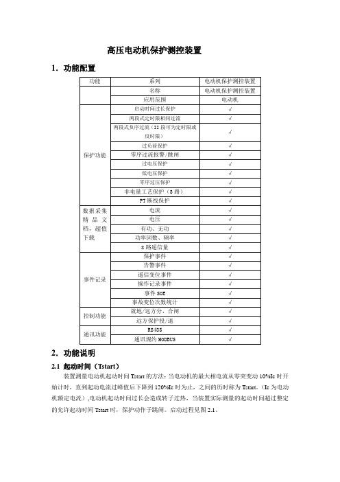
TLB-3 型脱离器
TLB-3 型脱离器采用热爆原理,设计新颖独特。
当避雷器损坏有工频续流通过时,脱离器内产生的热量使炸药引爆,将外壳炸开,从而彻底使避雷器与地线脱离。
其性能完全符合GB11032避雷器用脱离器的技术要求,填补了我国在该技术领域的空白。
本脱离器为附件型自成一体,两端通过M10螺栓与避雷器及地线相连(见图14-1),外型尺寸(见图14-2)。
明显的断开标记,便于及时检修。
PULS 长电缆电压保持应用说明书

The sheer size of systems suchas printing machines, conveyor belts, steel rolling mills or bottling plants require longcables connecting the individual electrical machinery and system parts.AN35.01.ENApplication NoteSufficient Voltage at the End of Long Cables.Michael RaspotnigData can be transmitted over long distances without problem. However,the same cannot be said about power for 24V devices. Severe voltage drops can occur if the wires are not sized properly. These voltage drops are often underestimated and can cause control components to fail or trigger a reset. Devices seldom draw current evenly. For example temporary volta-ge fluctuations can occur when a motor is connected and draws a high starting current so analyzing the cau-ses of the failure is therefore much harder. We get similar effects when connecting loads with large input capacities.In this case one solution is to connect a DC/DC converter as a “24 volt refresher” upstream of the loadwhich generates a regulated 24V vol-tage to compensate for the fluctuati-on. DC-UPS’s or buffer modules are ineffective in this situation.Decentralized power supplies Locating the power supply unit close to the device is one remedy as the drop at the 230V or 400V end is negli-gible due to the lower current. This would also counteract the general trend for decentralization.However, 24V power supply units for control circuits are generally still loca-ted in a central control cabinet. One reason is the desire to not have a dangerous voltage of 230V or 400V in decentralized control cabinets or machinery parts. Another reason is reducing the number of power supply units. It is simpler to adapt to the mains power supply with one central, standardized 24V power supply, depending on the country.Calculating the voltage drops across wires.Wire cross-sections (size) are selected according to taste or taken from charts which recommend a cross section according to the ampere value. These chart values are general-ly optimized to the admissible cable heating, not to the voltage drop. Undersized cross sections are often the result. Calculating voltage drops on wires is no great feat but does involve mastering some of theuncommon values for material pro-perties, cross sections, line lengths and their odd properties.The following diagram will help explain: For example, if one powers a display panel located 30m away(=60m wire lengths) which requires a current of up to 4A one would expect a standard wire with a cross-section of 0.75mm2to be adequate. The dia-gram shows a voltage drop of 4.5V for a 1mm2line. Converted to0.75mm2this gives a voltage drop of 6.75V which means that just 17.25V reaches the display panel instead of 24V. And this at a current of just 4 amps! These kinds of voltage drops cannot be compensated for simply by turning up the voltage on the power supply unit.Not all DC/DC converters aresuitableIt is important that the DC/DC conver-ter has a broad specified input volta-ge range and that the input shut-down voltage is very low. This enablestransient voltage dips to be bridgedmore efficiently. The converter itselfmust not cause an unnecessary cur-rent load on the input cable whichwould lead to a further larger voltagedrop and which could damage thesystem. The DC/DC converter shouldinstead actively limit the peak inputcurrent which occurs for instancewhen charging capacitors.All these characteristics were takeninto account when developing thenew CD5 DC/DC converter family fromPULS. As well as a broad input volta-ge range, the devices also have anactive inrush current limiter plus asoft-start function.Thanks to the soft-start functionthere is no need to worry about highinput currents if choosing a 5A devicefor 1A load current. The input currentalso adjusts to the load current duringthe switch-on phase.Figure 1:Voltage drop acrossa 1mmlength of the wire at awire temperature of 30°C.Voltage drop across the wireLength of wireThe benefit is best explained with the following example: A controller at the end of a cable has a relatively large buffer capacitor and an average current consumption of 1.5A. Based on the low current, a correspondingly small cross-section wire is selected. To compensate the voltage loss on the cable, a 5A standard DC/DC converter is utilized to refresh the 24V. If we switch on the 24V power supply, the following takes place: The DC/DC con-verter will want to charge the capaci-tors in the control unit with its maxi-mum possible current (typically 6.5A).In addition, the internal input capaci-tors in the DC/DC converter also need recharging. This naturally leads to a high current at the input of the DC/DC converter which forces theDC/DC converter into an undervoltage shut-down based on the voltage drop on the line. The result is a sequence of start-up attempts or no start up at all. It would be possible to improve this situation by selecting a 2A device,however, there is not a great deal of choices with DC/DC converter so you have to choose from what is availa-ble.The new CD5 series has addressed these problems. After applying the input voltage, the default value for the maximum output current rises slowly to the required value. Loads connected to the output and capaci-tors are thus charged gently. Of coar-se the start process takes a little lon-ger but this method effectively pre-vents a high input current during the switch-on phase.CD5: The New DC/DC converter family from PULSAs well as refreshing voltage losses at the end of long wire runs, the new DC/DC converter series has many more possible uses:Generating a stabilized control vol-tage in battery powered devices Galvanic isolation of control current circuits to avoid ground (earth)loopsMobile applications e.g. in ships,forklifts, …Figure 2:CD5.241: Soft-start without noticeable current increase(24V, 5A constant current load)Figure 3:CD5.241: Soft-start function. No unnecessarily high input currents during the switch-on phase.Active InrushCurrent LimitationSoft-start function5.5A5.5AInput Current Input VoltageOutput VoltageOutput VoltageFig. 3Input CurrentAs well as the 24V to 24V “Refresher”described here, there are other DC/DC converters which convert 24V to 12V or 48V to 24V.All DC/DC converters have a galvani-cally isolated output and are specified with 120W over the temperature range of –25°C to +60°C (12V version: 96W). Higher currents can be achie-ved by paralleling DC/DC converters. The devices also have a 20% power reserve which can be drawn continu-ously below +45°C.The flat design allows installation in standard decentralized 120mm on-machine cabinets and the width of just 32 mm saves plenty of space on the DIN-rail. The integrated soft-start, the electronic inrush current limiter, the reverse polarity protection at the input and the extensive approval pak-kage ensure a simple and problem-free installation.The CD5.241-S1 offers a useful featu-re for battery powered applications and is equipped with two relay con-tacts. The “Input-Low contact“ can detect when a battery is running low while the “DC-OK contact“ is desi-gned for building redundant systems. In this device the input/output termi-nals are also equipped with vibration-proof quick-connect spring clamp ter-minals. All other devices have screw terminals for the connection of wires.Ultimately these DC/DC converters do more than just adjust voltages. They contribute to system reliability and increase endurance in the event of voltage fluctuations. Thanks to their compact design, retrofitting is almost always possible.。
LHQ电缆层保护器相关型号列表参数

电缆层保护器特点
1、优异的保护特性,有效限制电缆金属屏蔽
层(或金属护套)感应过电压和故障过电压; 2、伏安特性曲线平坦,通流能力大,保 护特性好; 3、硅橡胶外套采用独有的界面偶联技术 和整体一次成型工艺,密封性能好,安全防 爆、免维护。
电缆层保护器图片参数
谢谢观看!
电缆层保护器
电缆护层保护器护层保护器用进口绝缘材料
作为外绝缘,电气性能优越,密封性能好, 较传统的放电间隙保护、带间隙碳化硅电阻 片保护等方式,其伏安特性更显优越 。
电缆层保护器使用条件
环境温度—45℃~+55℃;
海拔不超过4500m;超出4500m可根据实际情 况特制。 电源频率:58~62HZ(60HZ)
LHQ系列电缆层保护器
型号列表及参数
简介
电缆护层保护器采用采用ZnO压敏电阻(或
ZnO阀片)作为保护元件,无串联间隙,保护
特性好,具有优良的电压-电流特性曲线,目 前已广泛用于电力系统高压电气设备的保护 。
电缆层保护器图片
电缆层保护器型号
LHQ-10 BYL-10 LHQJS-10 BYLJS-10 LHQ-35 BYL-35 LHQJS-35 BYLJS-35 LHQ-110-Ⅰ BYL -110-Ⅰ LHQJS-110-Ⅰ BYLJS-110-Ⅰ LHQ-110-II BYL -110-II LHQJS-110-II BYLJS-110-II LHQ-220 BYL -220 LHQJS-220 BYLJS-220 注:LHQJS(BYLJS)表示带计数器电缆保护器
高压电机保护器说明书
高压电动机保护测控装置{TC "三.PD319-361A电动机保护测控装置" \f C \l "1" }1.功能配置{TC "1.功能配置" \f C \l "2" }2.功能说明{TC "2.功能说明" \f C \l "2" }2.1 起动时间(Tstart){TC "2.1 起动时间(Tstart)" \f C \l "3" }装置测量电动机起动时间Tstart的方法:当电动机的最大相电流从零突变动10%Ie时开始计时,直到起动电流过峰值后下降到120%Ie时为止,之间的历时称为Tstart。
(Ie为电动机额定电流),电动机起动时间过长会造成转子过热,当装置实际测量的起动时间超过整定的允许起动时间Tstart时,保护动作于跳闸。
启动过程见图2.1。
装置设两段定时限过流保护。
Ⅰ段相当于速断段,电流按躲过启动电流整定,在电动机起动完毕后自动下降一半。
这样即可以有效地躲过电动机的巨大启动电流,又可以保证电动机正常起动后提供防备严重的过负荷造成的堵转保护。
动作时限可整定, 对于用断路器控制的电动机整定时间一般较短,而用接触器控制的电动机整定时间一般较长,可选择整定为0.3秒,该段主要对电动机短路提供保护。
Ⅱ段是定时限过流段,在电动机启动完毕后自动投入,该段电流也可根据启动电流或堵转电流整定,主要对电动机启动时间过长和运行中堵转提供保护。
本装置设置二段相间过流保护,各段的投退控制定值可独立控制各段的使用情况。
投退控制定值取值含义都为:0:退出, 1:投入相间过流保护设有软压板,只有软压板和投退控制定值均为投入时,相应的保护段才投入。
2.3 负序过流保护{TC "2.3 负序过流保护" \f C \l "3" }负序电流保护主要针对各种非接地性不对称故障,出现较大的负序电流,而负序电流将在转子中产生2倍工频的电流,使转子附加发热大大增加,危及电动机的安全运行。
高压综保保护功能及定值说明
电动机起动检测:检测电动机机端的最大相电流,当最大相电流从没有电流流变为有电流,(大于0.1 Ie)认为电动机起动开始,电动机正常起动时电流很快增大到1.12 Ie以上,当电流降到1.12 Ie时则认为起动结束。
当电流很快增大到1.12 Ie以上后,电流一直降不下来,但电流值又小于起动速断定值(速断1段),装置认为电机一直处于起动状态,则“起动后速断定值(速断2段)”尚不起作用(既无论电流是否大于速断2段),在这种情况下装置的“起动超时保护功能”(设定的电动机起动时间)就发挥了作用。
如电动机采用降压起动方式或者其它如汽轮机带动方式起动时,如果机端最大相电流一直小于1.12Ie,则装置在设定的起动时间结束后认为电动机起动结束。
电流速断保护:作为中小型电动机定子绕组及其供电电缆相间故障的保护。
电流速断保护定值在电动机起动过程中与正常运行时分别整定,起动过程按速断高值,结束后为速断低值。
高值按躲开正常起动时的最大起动电流(应取实测值,如无实测值,可取系数7)并乘以1.5的可靠系数来整定(既10.5Ie);低值应考虑当供电电源短时中断或区外严重故障切除后母线电压恢复时,电动机处于自起动状态,但装置又不进行起动的识别功能,这时的起动电流比静态起动时要小(电机转子依靠惯性仍在转动)但要比额定电流大几倍的情况,故一般低值取5 Ie,(?此外,还应该躲过供电母线三相短路故障时电动机的反馈电流,反馈电流可取起动电路的89%)速断保护动作时限:当采用真空断路器或少油断路器控制时,动作时限为0S,保护以断路器的固有动作时间出口。
当采用熔断器――高压接触器控制时,其时限应与熔断器熔断时间配合,当故障电流大于高压接触器允许的切断电流(一般为3800A)时,熔断器应该在保护动作前熔断。
反时限过流保护:电动机起动完成后的保护,作为速断低值(5 Ie以下)或其他保护的后备保护。
2Ie≤I<5Ie 时限:5S堵转保护:电动机起动结束后投入,起动过程中发生的堵转由起动超时保护功能保护动作。
智能高压电缆接地箱技术说明书

因此需要建立一套既防盗,又能实时在线监测的系统来解决目前电力 电缆实时运行中的电缆环流、电缆护层电压、电缆温度、设备安全问题。 根据上述的现状需求,我公司研发生产的智能型高压电缆接地箱,内置一 套高压电缆在线监测系统,来监测接地环流的状况,监测电缆中间接头的
4.1.1 市电供电方式:220V 交流供电 4.1.2 电缆感应式 CT 取电:(目前此功能处于可拓展功能) 电缆感应取电方式及技术参数
5
这种取电方式采用在主电缆上安装 CT 取电环,在主电缆有电流通过时通
过 CT 环感应取电,一方面供给主板电源,同时也给蓄电池充电,其主要
技术参数如下:
额定工作频率(一次侧) 50Hz
板,给主板和蓄电池供电,这种方式比较稳定可靠,常采用这种方式进行
取电。
主要技术参数如下:
输出电压:DC15V~18V
输出最大电流:1.68A
开路电压:20V
短路电流:3.6A
功率:30W
重量:2.4KG
6
4.2 信息采集板参数(根据实际情况写,包含电流、电压、温度、防盗
传感器参数)
4.2.1、精确接地电流采集装置技术参数
主要技术参数如下:
技术参数名称
主要技术参数指标
备注
待机电流
<100μA
电流采样范围
0~100A
分辨率
12bit
转换时间
10μs
线性误差
±1LSB max
高压保护器使用说明书

GPZB-I微电脑智能综合保护装置说明书目录1 系统综述 (3)1.1 系统概述 (3)1.2 系统特点 (3)1.3 系统构成 (4)2 产品特点 (5)3 技术指标 (5)3.1 工作环境要求 (5)3.2 功率消耗 (5)3.3 主要保护功能配置 (5)4 保护原理 (6)4.1 速断保护 (6)4.2 零序过流保护 (6)4.3 过电压保护 (7)4.4 过载反时限保护 (7)4.5 低电压保护 (8)4.6 绝缘监视保护 (9)4.7 三相不平衡 (9)5 人机对话操作说明 (9)5.1 人机对话简介 (9)5.2 主菜单说明 (10)5.3 测量数据 (11)5.4 定值整定 (12)5.5 保护功能整定及解释 (12)5.6 密码管理 (16)5.7 事件查询 (17)5.8 试验项目 (17)5.9 附加功能 (18)5.10 出厂设置 (20)6 关于B相电流 (20)6.1 只对开关A相通电流 (21)6.2 只对开关C相通电流 (21)6.3 A相、C相同时通电流(接线方式1) (22)6.4 A相、C相同时通电流(接线方式2) (22)7 关于485通讯 (23)8 关于CAN通讯(选配) (23)9 用户安装调试、维护说明 (23)注意事项 (23)10 常见故障排查 (24)11 航插(26芯)引脚说明 (24)附件:产品接线图1、系统综述1.1 系统概述煤矿井下高压供电系统线路短、多级变电所级联,高压供电线路的布线特点使得常规继电保护装置不能通过整定值和时间级差的方式有选择的跳开故障点开关,出现“越级跳闸”问题。
我们根据煤矿井下高压供电线路的实际情况,采用全系统智能零时限防越保护方式,以辐射型高速通讯网络实现上下级继电保护装置的配合,为井下的高压供电系统的每台高爆开关提供可靠、全时、动态、高速的防越信息通道,每一台开关不再独立运行,而是以相同的节拍成为防越保护系统一部分,基于全站的防越保护系统提高了高压供电线路的可靠性和故障动作时间的实时性。
36702高压电缆线路保护1说明书

高压开关整定计算说明书###############################################################################计算公式及参数:过载保护动作电流计算公式:∑⨯=E rel aocI K I (A ); 速断保护动作电流计算公式:∑+⨯=)(E q rel aqI I K I (A ); 通过开关负荷电流计算公式:ϕcos 3⨯⨯⨯=∑∑N eX E U P K Irel K :可靠系数;X K :需用系数;ϕcos :功率因数;b K :变压器的变压比;N U :开关额定电压;∑e P :负荷总功率; q I :最大电机起动电流;##############################################################################1.编号:GK开关编号:GK ;型号:BGP9L-6-100;开关额定电压:6 KV ;负荷总功率∑eP :1225KW ;功率因数:0.85;同时系数:1 (1)过载保护动作电流:ϕcos 3⨯⨯⨯⨯⨯=⨯=∑∑N ex s rel E rel aoc U P K K K I K I= 1.05×1×0.498×12253×6×0.85= 72.51A ;过载保护动作电流实际整定值:100A ; 继电器的动作电流:=⨯=iaoc c dz K I K I 1.732×10040 =4.33(A );动作电流取5(A )。
(2)速断保护动作电流:最大电机总功率e P :200KW ;最大电机起动电流:135.85A ;速断保护电流整定计算: ⎥⎥⎦⎤⎢⎢⎣⎡⨯⨯-⨯⨯+⨯=+⨯=∑∑ϕcos 3)()(N e e x s q rel E q rel aq U P P K K I K I I K I=1.2×[ 135.85 +1×0.498×(1225 -200)3×6×0.85] = 232.37A;速断保护电流实际整定值:1200A ;继电器的动作电流:=⨯=i aqc dz K I K I 1.732×120040=51.96(A );动作电流取60(A )。
- 1、下载文档前请自行甄别文档内容的完整性,平台不提供额外的编辑、内容补充、找答案等附加服务。
- 2、"仅部分预览"的文档,不可在线预览部分如存在完整性等问题,可反馈申请退款(可完整预览的文档不适用该条件!)。
- 3、如文档侵犯您的权益,请联系客服反馈,我们会尽快为您处理(人工客服工作时间:9:00-18:30)。
5/4
5.5
400
50
LHQ-110(Ⅰ)
110
6/4
15
6.5
400
50
LHQ-110(Ⅱ)
110
10/4
25
11.0
400
50
LHQ-220(Ⅰ)
220
6/4
12
5.8
400
50
LHQ-220(Ⅱ)
220
13.6/4
31
15
400
50
LHQ-500
500
7.5/4
18*
8.3
400
50
* 注:雷电冲击电流16kA下的残压
4、如配置放电计数器或监测器能自动准确记录保护器在各种过电压下的动作次数及运行质量。
型号说明
依据国家行业标准JB/T8459-1996《避雷器产品型号编制方法》规定,电缆护层保护器型号如下:
电缆护层保护器电气参数表
型号
系统额定电压
kVr.m.s
工频耐压/时间
kVr.m.s
10kA雷电冲击电流下的残压
≤kVp
直流U1mA参考电压
≥kV
2ms方波通流容量
A
0.75UU1mA下的泄漏电流
≤μA
目前市场上流通的未按国家行标JB/T8459标注的型号
LHQ-6
6
1.9/4
4.6
2.1
400
50
BHQ、BYL、
FBY、SHQ、BYLS、
TBP-D
LHQ-10
10
3.6/4
8.7
4.0
400
50
LHQ-35
产品特点:
本公司针对一端接地的电缆线路及交叉互联的电缆线路设计的硅橡胶电缆护层保护器具有如下的特点:
1、采用大容量低残压的优质Zn0芯片, 具有通流容量大,保护比高的特点;
2、最大地限制、减少电缆线路金属护层中的工频感应过电压和冲击过电压;
3、硅像胶外套整体模压, 密封性好, 防污能力强, 重量轻、体积小、防碰撞、耐热、耐寒、耐老化、免维护;
电缆护层绝缘耐受电压值(DL/T401-1991)《高压电力电缆选用导则》
电缆额定电压/系统额定电压Ue/U
1min工频耐受电压Kv
雷电冲击耐受电压kVp
37/63、48/63、64/110
24
37.5
127/220
24
47.5
190/330
24
62.5
290/500
24
72.5
制造:上海昌开电器有限公司
高压电缆保护器
LHQ-35kV大截面电力电缆和66kV、110kV及以上电压等级的电力电缆均为单芯电缆, 电缆金属护层一端三相互联并接地, 另一端不接地。 当雷电波或内部过电压波沿电缆线芯流动时, 电缆金属护层不接地端会出现较高的冲击过电压, 或当系统短路事故电流流经电缆线芯时, 其护层不接地端也会出现很高的工频感应过电压。上述过电压可能击穿电缆外护层绝缘, 造成电缆金属护层多点接地故障,严重影响电力电缆正常运行甚至大幅减少电缆使用寿命, 因而电力行业标准DL/T401-1991《高压电力电缆选用导则》规定: 必须采用电缆护层保护器以限制电力电缆金属屏蔽层(或金属护套)上的感应电压和故障过电压。