koomy unit 封井器远程控制台说明书
迈克罗斯 47007-0005450 远程控制器用户指南说明书

For countries outside the European Union:
If you wish to discard these items, please contact your local authorities or dealer and ask for the correct method of disposal.
• If you must operate this unit while driving, do not take your eyes off the road or an accident could result.
• If any of the following problems occur, immediately stop using this unit and consult your dealer from whom you purchased this unit: – smoke coming from the unit. – abnormal odors or smells. – a foreign object has entered the unit. – liquid has been spilled on or into the unit. If you continue to use the unit when it is not operating properly, damage could result in an accident or fire.
Notes
• Depending on the car stereo, there may not be some buttons with the same names as those on this unit.
柯斯米

④ 注意,延迟时间如果设定在“0”附近的位置,可能会随干扰信号动作。
⑤ 设定的延迟时间期间,输入信号如果向一定方向变化,输入信号即使未到达最终目标点,
执行器也会先动作。例如,输入信号在延迟时间期间连续从 4mA 向 20mA 变化时,执行器一
边先向 20mA 方向运行,一边不断确认目标值。
2
柯斯米
都在 On 或都在 Off 上)(如图四或图五所示)。
③ 输入信号为0~5V DC和0~10V DC时,不提供Fail Safe Position ON
(失电安全位置)功能。
123456
4)DELAY TIME(延迟时间)
(图五)
DELAY TIME ① 预防无线电干扰、其它外来干扰导致执行器误动作。
2) 输入信号变更 (例如:从 4~20mA DC 变为 2~10V DC)
① 先把输入信号选择用DIP 开关设置为与2~10V DC对应。 (参照输入信号选择示图)。
② 把DIP开关4(CH1)打开(如图一所示)。
ON
123456
(图一)
F-CLOSE F-OPEN A-FULL CH1 CH2 REV
“失电”是指失去控制电信号,而非失去电源!
(图三)
F-CLOSE F-OPEN A-FULL CH1 CH2 RE V
FAIL CLOSE(失电关闭):如果 RPC 上没有输入信号,执行器自动运行
到全关(Dip 开关的 1 号<F-CLOSE>置于 On<开>位置)(如图二所示)。
① FAIL OPEN(失电打开):如果RPC上没有输入信号,执行器自动运
③ 输入2V DC输入信号,按ZERO(零点)按钮2秒钟以上。
远程控制台.原理及操作PPT课件
3.空气管缆
空气管缆用以连 接远程控制台与司钻 控制台之间的气路。 气管缆由护套及多根 管芯组成,两端装有 连接法兰,分别与远 程控制台和司钻控制 台相连。
3.结构与特点
Shanghai Shenkai International Trade Co.,LTD8
3.结构与特点
4.液压管线 一般情况下,远程控制台与井口防喷器组之
3000 psi 0~2000 psi 1000±100psi
2700~3000psi 93~115psi
4
Shanghai Shenkai International Trade Co.,LTD
3.结构与特点
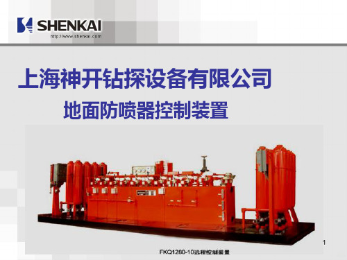
FKQ系列地面防喷器控制装置主要由以下部件组成: 1.远程控制台 2.司钻控制台、辅助司钻控制台 3.空气管缆 4.液压管线(包括软管线或者管排架等管线)
手动减压阀 双作用气缸
球阀 压力控制器
截止阀 6
气动调压阀 Shanghai Shenkai International Trade Co.,LTD
2.司钻控制台
FKQ系列控制 装置可以配有司钻 控制台。司钻控制 台通常安装在钻台 上,使司钻能够很 方便地对防喷器实 现遥控。
3.结构与特点
Shanghai Shenkai International Trade Co.,LTD7
4.控制装置工作原理
1.液压能源的制备、储存与补充 如图所示,油箱里的液压油经油阀、滤清器进入电动泵或气动泵,
电动泵或气动泵将液压油升压并输入蓄能器组储存、蓄能器组由若干 个钢瓶组成,钢瓶中预冲7MPa的氮气。当蓄能器钢瓶中的油压升至 21MPa时,电动泵或气动泵停止运转。当钢瓶里的油压过分降低时, 电动泵或气动泵自动启动往钢瓶里补充压力油。这样,蓄能器的钢瓶 里将始终维持有所需要的压力油。 气动泵的供气管路上装有分水滤气器、油雾器、压力调节器以及旁通 截止阀。通常,旁通截止阀处于关闭状态,只有当需要制备高于 21MPa的压力油时,才将旁通截止阀打开,利用气动泵制造高压液 能。
交流矿井提升机TKDPC系列电控使用说明书
目录1、电控设备技术特性及适用环境1.1 电控设备技术特性1.2 电控设备使用环境2、电控系统的主要组成部分与作用2.1 PLC 简介2.2 主回路2.3 安全回路2.4 测速回路2.5 控制回路2.6 辅助回路3、系统的保护与联锁4、线路动作简介5、PLC 控制的优点6、产品安装与包装标志7、产品的维护和保养1、电控设备技术特性及适用环境1.1 电控设备技术特性本电控设备适用于单绳牌坊式提升机,包括单筒、双筒,单水平、多水平(最多不换层8水平,换层4水平),也可适用于多绳监控器或牌坊式,采用具有远程智能站的操作台、含数字式深度指示的提升机。
1.2电控设备使用环境(1).环境温度不高于40℃、不低于-5℃。
(2).相对湿度不超过85% (+25℃)。
(3).没有导电尘埃及对金属和绝缘有破坏作用的气体。
(4).没有剧烈的振动和颠簸。
(5).不必防爆的地方。
(6).采取措施后能满足上述条件的场所。
2、电控系统的主要组成部分与作用2.1.PLC 简介PLC系统由一个主PLC系统(A)和一个从PLC系统(B)组成。
主PLC系统放在主令柜里,它由一个基本单元(FX2N-80MR)、一个扩展输入模块(FX2N-16EX),二个功能模块(FX2N-4AD,FX2N-2DA)及一个通讯模块(FX2N-485-BD)组成。
从 PLC系统放在操作台里,它由一个基本单元(FX2N-80MR)、一个扩展输入模块(FX2N-16EX),二个扩展输出模块(FX2N-16EYT)及一个通讯模块(FX2N-485-BD)组成。
①.数字量模块:FX2N-80MR,FX2N-48MR,FX2N-16EX用于开关量信号的输入和输出。
输入/输出点数分别为:40/40,24/24,16/0。
②.模拟量模块:FX2N-2DA为模拟量输出模块,用于两路模拟量信号的输出。
FX2N-4AD为模拟量输入模块,用于四路模拟量信号的输入。
2.1.1安装注意事项:①.不宜安装在含有灰尘、油烟、导电性粉尘、腐蚀性及可燃性气体的场所。
Rimikon IP 控制器产品说明书

Product ManualName : Rimikon IP CONTROLLERModel : RIM-IPC1275 Leeds ave Suite 800 Ottawa , Ont Canada K1B 3W2 1877-470-7480Product Info∙This IP Controller is designed for Rimikon's Extra Low Voltage LED Products.∙This unit is IP addressable or WIFI and can be used with the Rimikon Android and IOS App.∙The remote control distance can reach up to 50 meters indoor and upp to 100 meters outdoor.Item Model DescriptionRimikon IP Controller RIM-IPC Used to control Rimikon's LED Lighting products1. Rimikon IP Controller Instruction1.Install Rimikon LED IP Controller APPFirst go to Google play or i tune store ,Search for the Rimikon.Download and install the Free Rimikon App.2.Connecting your devise ( mobile or tablet) with theRimikon IP Controller.1. Do Not Plug the RIMIKON power supply into the electrical outlet till allsteps are done .2. Connect the Rimikon power supply low voltage output to the IP Controller .( see figure 1)3. From the IP Controller connect Rimikon’s LED lights.4. Connect the Rimikon power supply AC input into the electrical socket oncesteps 2 and 3 are completed. (see figure 1.)5. Go to your device settings and turn on WiFi then select the SSID –LEDnet.xxxxxxxx and use password 88888888 (see figure 2 )6. Lauch the Rimikon App7. Once the scan is complete , select the Rimikon IP Controller in the devicelist. (see figure 3)1) 2) 3)3.Renaming the IP Controller in your device list1. Launch the Rimikon App2. Scan for the Rimikon IP Controller ,once scan is complete use a long presson the Rimikon IP Controller name and change the name .see figure 3 and 43) 4)4 .How to change the SSID and password1. Launch the Rimikon App2. Scan for the Rimikon IP Controller, once scan is complete select the RimikonIP Controller in the device list and select settings, then select device settings ,select change under LED device security settings. (See figure 5.6.7.8.)5) 6) 7) 8)5.Link the Rimikon IP Controller to your Router.1. Launch the Rimikon App2. Scan for the Rimikon IP Controller, once scan is completed select theRimikon IP Controller in the device list , select settings, select device settings,select Link to wireless router in network mode. (see figure 5.6.7.9.)5) 6) 7) 9)6.How to find your Mac address for hard wire connections.1. Launch the Rimikon App2. Scan for the Rimikon IP Controller, once scan is completed select theRimikon IP Controller in the device list, select settings , select device settings and right the Mac address .see figure 5,6,73. Once you have fond the Mac address ,Disconnect power to the Rimikon IPController and place the switch in the network position on the front of theRimikon IP Controller.4. Plug the Ethernet cable from the Router into the RJ-45 connection on thefront of the Rimikon IP Controller.5. Connect the power to the Rimikon IP Controller .6. Connect your device using your home WiFi network and launch the RimikonApp, select the Rimikon IP Controller in the device list and select settings ,select device settings and confirm the Mac / IP address.5) 6) 7)7. Software Operating (Single Color ) How to use Single color mode.1) Load Rimikon App on your device .2) Brightness: you can change it from 0 to 100%3) Power button : On and OffSPEC SHEETItem Model DescriptionRimikon IP Controller RIM-IPC Used to control Rimikon's LED Lighting productsSpecs :Item Version : Single Color version 1.01. Working Voltage DC7.5-24V2. Output current : 4Amp3. Connecting method: Terminal4. Dimension: L11cm*W 7cm*H 4cm5. Remote Distance : 50 meters indoor ,100 meters outdoor6. Software: Android ,IOS, Version 1.0 with WIFI7. Receiver sensitivity: 802.11d DSSS(-5DBM) 802.11d CCK 802.11gOFDM(-15dBm)8. Connection : V+ V- for LED lights, V+V- or 2.5mm jack for Power supply.9. Reset button ( on front of unit) 5 secound hold for factory reset10. Wifi SSID for connection is LEDnetXXXXXXXX passsword:888888881275 Leeds ave Suite 800 Ottawa ,Ont Canada K1B 3W2 1877-470-7480。
米高远程监控系统说明书
电梯参数 显示电梯参数以及层高及呼钮设置信息 电梯参数包括楼层数 轿门数 梯速以及脉冲基数
数据帧内容 显示所接收到的帧内容
历史故障 显示电梯的历史故障信息且设有打印功能 用户可以打印故障信息报表
循环时间 控制电梯监控页面中各子页面的自动循环显示时间 如设为 0 则各子 页面停止自动循环 可以通过点击页面来看所需的信息页面
高级用户可单击不同的图标进入电梯监控导航界面 系统管理或数据维 护系统 使用时 可让鼠标在图标上稍作停顿 根据界面左下方状态栏 中出现的提示进行操作 一般用户直接进入电梯监控导航界面
PAGE 3 / PAGE 24
MICOCONTROL
电梯远程监控系统操作手册
第三章 主界面的使用
高级用户主界面画面上有三个图片 系统管理 数据维护 监控中心
PAGE 6 / PAGE 24
MICOCONTROL
电梯远程监控系统操作手册
PAGE 7 / PAGE 24
MICOCONTROL
电梯远程监控系统操作手册
第六章 数据维护界面说明
数据维护界面主要分菜单 工具栏和数据显示三个区域 数据显示区域也分三部分
左边为树状窗口 分级显示产品资料 右上部为地图显示窗口 用户可以点击地图 逐次进入 右下部为一表格区 如现在所在地图有下一级信息 子地图或客户 则会在表格中显示信息 表格中 标志为 M 的是地图信息 标志为 V 的是客户信息
页数
2-2 3-3 4-4 5-5 6-7 8-8 9-9 10-10 11-11 12-13 14-14 15-16 17-17 18-18 19-19 20-20 21-22 23-24
PAGE 1 / PAGE 24
主井皮带操作台控制系统使用说明书

皮带操作台控制系统使用说明书一、操作台功能概述本系统采用触摸屏和可编程序控制器相结合,实现主井皮带电机的手动与自动起动。
手动时,可使用操作台上的手动按钮来控制主井电机、液力耦合器的执行器及制动器的起停,自动时可使用操作台上的自动旋钮来实现电机及其它设备的控制,自动实现电流平衡、起动预警,及所有皮带保护,设备故障,勺杆推拉的联机控制,且操作台上设置了打点、送话功能,沿线双向送话,可显示电流、电压、带速、油温,以及设备开停时间,故障时间及故障时的电流等。
可显示皮带保护的各种故障地址。
系统主要采用三菱PLC可编程控制器,EVEIW触摸屏,模拟输入模块,数显表。
系统功能概述:1、手/自动切换2、手,自动开停主电机、勺杆、制动器3、紧急停车4、开车预警5、送话及打点6、故障复位7、电机运行、停车及故障状态指示8、电机电流、电压、油温及带速显示9、皮带拉绳、跑偏、打滑保护及地址显示10、皮带运行时间及设备开停故障时间显示二、操作说明★(1)手动运行开车:高压柜合闸,操作台右下角电源指示灯亮→将操作台左边万转打到“2”上开2#冷却泵→将手动/自动开关打到手动位置→按下手动预警按钮→按下1#电机启动按钮→8秒后按下2#电机启动按钮→打开制动旋钮→同时按下1#和2#勺杆拉按钮,按2秒停4秒直到电机开到预设的速度。
当皮带开起来后,时刻观察1#和2#电机电流的平横。
当其中一个电流过小时可单独点动拉其勺杆或点动推另一勺杆。
停车:按下打点按钮→同时推1#、2#勺杆直到其推到指示灯亮→停1#、2#电机→手动关制动器。
急停:按下急停按钮即可全部停车。
★(2)自动运行开车:高压柜合闸,操作台右下角电源指示灯亮→将操作台左边万转打到“2”上开2#冷却泵→将手动/自动开关打到自动位置→将自动旋钮打开→皮带将会自动缓慢运行直到开到正常速度。
停车:将自动旋钮关闭即可。
急停:按下急停按钮即可全部停车。
★(3)注意在开车前确保各皮带保护均正常,确保无故障方可开车。
功尊 RTU-100X 智能远程终端控制柜 说明书
RTU-100X智能远程终端控制柜说明书功尊仪表(浙江)有限公司目录一、 产品概述 (1)二、 技术特点 (1)三、 工作原理 (2)四、 外观及接口 (3)4.1实物图 (3)4.2规格参数 (3)4.3内部组成 (4)4.4功能结构 (5)4.5 RTU终端 (5)五、 RTU与外围设备通讯及连接 (6)5.1仪表接入 (6)5.2安防系统接入 (8)六、 安装调试 (9)6.1外形尺寸 (9)6.2安装 (9)6.3接线 (10)6.4安装规范 (11)6.5调试 (11)6.6安装注意事项 (11)七、 常见故障分析及处理 (12)八、 质量承诺 (12)九、 运输和贮存 (12)十、 开箱及检查 (12)尊敬的用户,感谢您购买本公司RTU-100X型智能远程终端控制柜产品,为确保能够安全、可靠、正确使用本产品,请仔细阅读本使用说明书,熟悉产品操作并严格遵守说明书的要求。
一、产品概述RTU-100X型智能远程终端控制柜(以下简称控制柜),是我公司专门为燃气仪表设备远程监控而设计一款物联网终端产品,它既可直接与各种流量计、变送器等燃气仪表连接,也可接入其它环境监测设备,通过4G无线通信技术,将现场仪表和设备与远程监控中心建立无线通信链接,完成数据交换。
控制柜可以和我司自主监控平台软件(SCADA系统)配套使用,实现前端设备的远程集中监控,也可以通过协议与第三方监控平台对接实现对其的集中监控管理。
通过监控平台软件,管理人员可实现对前端设备的集中管理,远程查看现场设备的实时数据、运行情况,采用分布式应用、集中监控、统一管理的原则,减少现场的人工投入,实现无人值守的目的。
同时,监控平台软件也可以根据控制柜发送的数据,进行统计分析,提高工作效率。
控制柜安装方便,且易于操作。
目前该产品已广泛应用于燃气、水务行业物联网抄表系统及SCADA系统的项目建设。
产品执行标准:执行Q/GZ 102.02-2022《智能远程终端控制柜》企业标准本产品符合GB3836.1-2021 《爆炸性环境 第1部分:设备 通用要求》和GB3836.2-2021《爆炸性环境 第2部分:由隔爆外壳“d”保护的设备》标准;防爆标志为Ex d IIC T6 Gb,经国家防爆电气产品质检中心检验合格,取得防爆合格证。
- 1、下载文档前请自行甄别文档内容的完整性,平台不提供额外的编辑、内容补充、找答案等附加服务。
- 2、"仅部分预览"的文档,不可在线预览部分如存在完整性等问题,可反馈申请退款(可完整预览的文档不适用该条件!)。
- 3、如文档侵犯您的权益,请联系客服反馈,我们会尽快为您处理(人工客服工作时间:9:00-18:30)。
The trademarks such as
R○
R○
R○
are Shenkai’s registered trademarks. Any use of other names related to the trade marks herein by any third party for its own purpose will infringe interest of the trademark owner.
Qualified Personnel Only qualified personnel are allowed to install and operate the equipment. Qualified personnel refer to those who, with experience in field well control, can install, test run and operate equipment according to established safety practices and standards.
Shanghai Shenkai Petroleum Equipment Co., Ltd. hereby declares that contents of this manual are verified and compliant with the said product. Mistakes, however, are unavoidable, so complete consistence can’t be guaranteed. Contents of this manual are subject to periodic review and will be modified in the next version. Your opinions on improvement are welcome.
Shanghai Shenkai Petroleum Equipment Co., Ltd. 1
Pneumatic Liquid Type Control System for Surface BOP Stacks
Safety Guideline The manual includes precautions that should be followed to ensure personnel safety and prevent products
The hydraulic control system not fitted with a driller’s console is applicable to drilling or workover operations and is simple and portable. The hydraulic control system can be fitted with a mechanical anti-lifting device (see the operation manual for the anti-lifting device). 2. Pneumatic liquid type FKQ hydraulic control system
and connected devices from being damaged. For these precautions, symbols are used for alarm purpose and the following descriptions will be given
depending on severity:
Copyright © 2009 Shenkai Company. The information in this manual is subject to change without notice.
2
Pneumatic Liquid Type Control System for Surface BOP Stacks
This hydraulic control system is fitted with a driller's console or an auxiliary driller's console (optional). Alarm type and non-alarm type driller's console and auxiliary driller's console can be installed as demanded by users. Air pipe bundles are used to connect the remote console with the driller’s console and the remote console with the auxiliary driller's console for the pneumatic liquid type hydraulic control system, so that the hydraulic control system can be remotely controlled on the driller's console and the purpose of opening and closing BOPs can be achieved. This hydraulic control system is generally used in drilling operations. The hydraulic control system can be fitted with a mechanical anti-lifting device (see the operation manual for the anti-lifting device). 3. Electrical and pneumatic liquid type FKDQ hydraulic control system
Ordering Instructions YTK-02 Pressure switch QB21-60 and QB21-80 Crankshaft Plunger Pumps JYS21-25 and JYSQ21-25 Relief Bleed Valves JYSQM21-25 Relief Bleed Valve QYB 40-120L Pneumatic Pump 34ZS21-25 3-position and 4-way Rotary Valve Illustrations of Wearing Parts of Other Hydraulic Valves
3
Pneumatic Liquid Type Control System for Surface BOP Stacks
Overview I. Introduction
The control system for surface BOP stacks (hereafter abbreviated to hydraulic control system) is very important equipment which controls BOP stacks and gate valves controlled by hydraulic pressure especially in drilling and workover operations. It is necessary to accurately operate and maintain the hydraulic control system. The hydraulic control system manufactured by Shenkai can be divided into 3 types: 1. Directly manually operated FK series hydraulic control system
The remote console is fitted with a driller's console or an auxiliary driller's console (optional). In addition, explosion-proof driller's console and auxiliary driller's console applicable to hazardous and explosive gas environment area I or II can be installed as demanded by users.
Copyright © 2009 Shenkai Company, All rights reserved.
Without the express written permission, it is forbidden to copy, transmit or use this manual or part of it. Any violation of the above will be disciplined. All rights, including patent rights, utility model or appearance design patent rights, are reserved.
Pneumatic Liquid Type Control System for Surface BOP Stacks
Pneumatic Liquid Type Control System for Surface BOP Stacks
Operation Manual
Overview Introduction to the Use of Pneumatic Liquid Type Remote Console