Honeywell温控器详细说明书
Honeywell-XL50控制器操作说明

Honeywell-XL50控制器操作说明1.可编程控制器和仪表可编程控制器XL20、XL50 (的核心元件,它在系统中起到重要作用:如检测各传感器的当前值,动态调整个比例阀的状态,显示系统各参数等;还提供了一些控制系统内部参数的调整和系统参数的设定方式,用户应对其操作方法和性能达到熟练的程度,才能实现空调系统的各种操作。
XL20为中文控制屏,不带通讯方式,操作方法雷同XL50。
取消键–返回先前的或上一级的屏幕;取消未被确认的操作;确认报警信息。
上移键–移动指针到前面的行下移键–移动指针到下一行右移键–移动指针到当前位置的右边左移键–移动指针到当前位置的左边增加键–每按一次增加数值一个单位或改变数字状态值到与当前状态值相反的状态值减少键–每按一次减少数值一个单位或改变数字状态值到与当前状态值相反的状态值确认键–确认已做的修改和进入下一个屏幕(指针在NEXT前)对于KTF空调系统的控制操作,主要是对系统参数的查看和更改(即对“系统参数操作键”的使用),该控制器的强大功能主要体现在:不但可以在线修改所有输入、输出点,而且也可以对控制系统的内部参数进行改变。
a)查看系统的输入、输出点状态(即查询新回风温度、露点温度、出口温湿度、风压及其各个阀门开度)♦ 重要说明:对DDC 控制器的操作只能单键进行,严禁同时按压键位,以避免不必要的误操作,以免程序被初始化或删除。
♦ 按下系统“参数”操作键,屏幕出现“请输入你的密码";密码输入才可以修改数据,比如压力等参数的设定等.用户只是查看的话就可以直接进入。
♦ 移动“光标移动"向上键,使光标停留在“****”上,再按下“输入键",通过使用“数据增/减键"和“输入键”逐个将4位密码输入,完毕后屏幕左下角出现‘更改change ’字符;光标移动到change 字符上可以修改进入DDC 修改数据的密码,默认为‘3333’,如更改了密码,用户须牢记更改后的密码,每次参数修改操作都需密码。
Honeywell C300控制器用户指南说明书

Process SolutionsHoneywell’s C300 controller provides powerful and robust control for the PlantCruise by Experion® platform. With the C300 and the Control Execution Environment,customers can improve engineering productivity and maintenance, maximize process uptime, and reduce production costs.At the core of the C300 in PlantCruiseis Honeywell’s field-proven deterministic Control Execution Environment (CEE) core software. The CEE provides a superior control execution and scheduling environment. Control strategies are configured and loaded through Control Builder, an easy to use and intuitive engineering tool.The C300 controller hardware offers unique space saving, installation, and maintenance benefits consistent with its innovative Series 8 form factor.The C300 is optionally redundant, requiring no additional hardware other than an identical second hardware module.The ‘designed-vertical’ C300 controller provides a superior control execution and scheduling environment.With the C300 controller, customers can:• Improve engineering productivity with a rich set of function libraries and a seamless and intuitive user environment, • Maximize process uptime and minimize maintenance effort with robust diagnostics and full hardware redundancy, and, • Reduce production costs with flexible and efficient control strategies, on-process migration, and efficient hardware processing power.Easy Control Strategy Creation through Rich Function LibrariesThe Control Execution Environment function blockssupport:• Continuous Control • Logic Based Control • Sequential Control • Model Based ControlEach function block contains a rich set of predefined features, such as alarm limits and priorities, various control algorithms, and maintenance statistics, all of which are configurable parameters. Function blocks are linked together in Control Modules to perform specific control tasks, which provide a foundation for efficient control engineering.Embedded functionality guarantees consistent control strategyexecution and delivers consistent alarming and operations behavior. This consistency reduces operator errors and saves implementation time by eliminating the need to develop low-level basic functions.The CEE fully supports the ISA S88.01 batch standard and integrates sequences with devices. The devices will track the state of the sequences and perform pre-configured actions based on those sequences. This reduces the implementation and complexity of handling abnormal situations. The SCMs support abnormal handling, recipe parameters, and on-line monitoring of the execution through chart visualization.One Seamless Environment through Easy Data CommunicationParameters provide access to every imaginable piece of information in the controller. This data can be used throughout the Experion system, whether for other control strategies or for operator purposes. For example, in custom displays, parameters such as setpoints or outputs can be historized and used in trend views. The engineer does not need to know where the information resides. Instead, he can just reference it, and the system manages the underlying logistics of that information. The system will notify the user based on the status information associated with the value and take appropriate action when required.Each parameter is also protected from accidental changes through a security access level, and certain parameters can only be changed off-line. Communication is based on report- by-exception and publish-subscribe, making efficient use of communication bandwidth by accessing data only when needed and avoiding duplication.Consistent and Predictive Behavior Makes Engineering and Maintenance EasierThe C300 CEE supports an execution period per control strategy, ranging from 50 msec to 2000 msec. The user can make changes to existing or add new control strategies without interrupting other control strategies executed by the controller. The user has full control over the function block execution order within the control strategy and the execution order of multiple control strategies. Control strategies can be easily moved between control environments by using the convenient drag-and-drop feature within Control Builder. Easy and Intuitive Engineering EnvironmentControl Builder is the control engineering and maintenance tool for the Control Execution Environment, and improves the control engineer’s productivity by simplifying configuration with a graphical user interface and predefined function blocks ready for wiring into a specific control strategy. The control engineer can enable and change standard function block features without the need to build these from the ground up. The control strategy can be documented with embedded objects such as text, documents or web-links.Online Monitoring Is Available to the Engineer and OperatorOnce control strategies are created and loaded to the C300 controller, the engineer can monitor the strategy on-line using the same graphical interface. This is helpful for verifying a control strategy or for troubleshooting a process problem. The control or maintenance engineer can directly modify parameters from the engineering environment without needing an operator interface. Controller Based Model Predictive Tuning with ProfitLoopProfit Loop is Honeywell’s patented algorithm that provides a single input / single output model-predictive function block that is included in the standard C300 controller function block library. It has the operating simplicity and computational efficiency of a standard PID function block, yet provides tight, robust control, increasing process stability by up to 30 percent. Profit Loop creates a simple model of the process to predict the effect of control moves on the process (controlled) variable. Because Profit Loop can anticipate future process behavior, the controller knows exactly how much to move the process to meet the desired control objectives. Profit Loop incorporates the best elements of both traditional PID algorithms and the model-based control and optimization technologies of Profit Controller at the regulatory level.For More InformationTo learn more about how Honeywell’sPlantCruise by Experion C300 Controller can improve plant performance, visit our website or contact your Honeywell account manager. Honeywell Process Solutions Honeywell1250 West Sam Houston Parkway South Houston, TX 77042Honeywell House, Arlington Business Park Bracknell, Berkshire, England RG12 1EB Shanghai City Centre, 100 Junyi Road Shanghai, China 20051 Custom Algorithm Blocks Custom Algorithm Blocks (CABs) are similar in purpose and structure to native function blocks included with Control Builder. These blocks have predefined algorithms and data structures. By contrast, Custom Algorithm Blocks have user defined algorithms and data structures. CABs are developed using Visual Basic integrated into Control Builder.The C300 controller supports the execution of CABs in Experion LX. CABs can greatly reduce the effort required to create complex control strategies that require the robust control environment offered by the C300.Investment ProtectionHoneywell is committed to protecting customer investments by supporting and integrating previous control products. Consistent with this philosophy, the Control Execution Environment, which holds the user application, is platform- independent. This allows the user to make use of new, more powerful hardware platforms when they become available, while retaining the specific user application.PN-13-16-ENG February 2014© 2014 Honeywell International Inc.。
Honeywell DT100RR RM RS 系列 数字式温控器 说明书
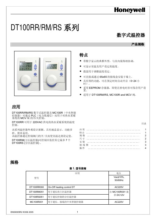
DT100RR/RM/RS 系列数字式温控器产品规格应用DT100RR/RM/RS数字式温控器及MC100R(中央智能控制器)可通过PLC(电力线通信)而用于对热水采暖系统的MCV阀的开/关控制。
DT100RR可用于220VAC供电的热水采暖系统的温度控制。
该系列温控器外观设计新颖、具有液晶显示、功能多样、简单易用。
该温控器通过控制阀门的开/关而使室温达到设定值。
DT100RM(主区温控器)可控制并监控其它最多7个DT100RS (分区温控器) 。
特点•带数字显示的典雅外型,与室内装饰相协调。
•可显示室温及用户设定的温度。
•拨盘用于调整温度设定。
•可直接或通过65x65的接线盒安装于墙上。
•具有预约功能,可在预定时间自动开启(0~24小时)。
•采用EEPROM 存储器,即使在掉电时亦可保存用户设置。
•适用于DT100RM/RS, MC100R and MCV 阀。
目录应用 (1)特点 (1)规格 (2)尺寸 (2)安装 (3)接线图 (3)操作 (4)规格表 1. 型号指南应用电压型号 Vac±10%,50/60Hz DT100RR000 On-Off heating control DT AC220VDT100RM051 用于通信的主区温控器DT100RS051 用于通信控制的分区温控器由 MC100R001 提供DC12VMC100R001 用于通信、接线的中央智能控制器AC220V设置范围 5~35℃ 最小设置单位 0.5 ℃ 差动 最大1 ℃ 温控开关 DT100RR - S.P.S.T. 继电器 MC100R - S.P.D.T.继电器 控制方式 开/关控制 供电5(2) A , 220 VAC ,12A 典型负载如风机盘管、分区阀门及继电器。
超过200W 的电感负载应通过电流接触器进行转换。
使用寿命 220V 全负载时,超过100,000 次(冷热循环)全手动控制时,超过10,000 次 安装 直接安装于墙上或安装于65x65mm 接线盒上,并用螺钉固定 接线 2线或3线(200mm)连接 外壳 两片塑料外壳(前盖及后盖) 尺寸 82 x 120 x 28mm(W x H x D) 环境要求 工作温度:5~45℃运输及储藏温度:-20~55℃湿度:5~95%RH, 26℃无冷凝尺寸图. 1 DT100RR/RM/RS, MC100R 尺寸 ( mm)< DT100RM > < DT100RR/RS >< MC100R >位置DT100 温控器是地板采暖系统的温度控制器件, 必须安装在距地面约1.5米高,空气流通良好的位置。
HONEYWELL温控器HCE60

StoreyControllerHCE 60 Mounting and OperationOverview C ONTENTSOverview3 Application3 Procedure during the installation4 Assigning zones and actuators4 Mounting4 Configuration and installation4 Configuration4 Creating a zone plan5 Specifying temperature zones5 Filling out the zone plan6 Mounting9 Wall mounting10 DIN rail mounting11 Mounting the Hometronic heating components11 Configuration and installation12 Opening the housing13 Cabling connections15 Configuration24 Preparing the configuration24 LED display at the storey controller26 Operating modes of the storey controller27 Buttons281OverviewAssigning zones and room names29 Example: Assigning an HCW 22 setpoint adjuster to Zone 130 Example: Assigning the room name LIVING to Zone 131 Assigning a remote setpoint adjuster HCU 30 to a temperature zone33 Assigning a setpoint adjuster of type HCW 23 to a zone33 Reversing the assignment34 De-installing room names at the Hometronic Manager35 Saving settings at the Hometronic Manager36 Checking the configuration36 Checking the radio transmission37 Checking the assignment of the room names37 Displaying faults38 Terminating the configuration39 Resetting the storey controller to the state of delivery40 Appendix41 Glossary41 Help for problems42 Overview of the Hometronic heating components45 Zone plan46 2Overview OverviewFor your informationTechnical terms are explained in the glossary (page 41). They are identified in the text by an *.ApplicationThe storey controller HCE 60 receives specifications for the room temperature from the setpoint adjusters* and the Hometronic Manager*. The storey controller controls the boiler regression*, the pump relay and the thermal actuators* (refer to page 45, Hometronic heating components) on the basis of these specifications.It disposes of a self-teaching control function (fuzzy logic) which adapts itself automatically to the environmental conditions. The desired room temperature is reached rapidly and held constant.In order to provide a rapid overview of the display and operation there is a sticker on the rear of the instructions which can be stuck onto the housing of the storey controller.3Overview 4Procedure during the installationAssigning zones and actuators• Specify which heating circuits* are controlled by the storey controller.Mounting• Mount the Hometronic heating components.Configuration and installation• Set the storey controller to the actuator type, cable the connections and interconnect the components.Configuration• Assign setpoint adjusters to the temperature zones.• If appropriate, assign room names at the Hometronic Manager.• If appropriate, assign the time program of the remote setpoint adjuster HCU 30 to the temperature zones.Creating a zone plan 5Creating a zone plan*A temperature zone is an area of the building – e.g. a room – in which the setpoint temperature* is set by means of a setpoint adjuster. The storey controller controls all the thermal actuators of a temperature zone to the same value.5 temperature zones can be set up per storey controller. The extension module HCS 60 increases the number of temperature zones per storey controller to 8. A maximum of 3 actuators can be connected in each zone.The total number of actuators which can be controlled by one storey controller is thus limited to 24.Specifying temperature zonesCaution Danger of damage through external equipment! The storey controller is designed only for components which have been authorized by Honeywell!► Only use actuators of the type H 200 BG (no-load closed) or H 200 BO (no-load open).► Combine all the actuators (type and location) which are managed by the storey controller.► Combine all the actuators which are controlled by a setpoint adjuster in a temperature zone.Creating a zone plan 6In case of more than 8 temperature zones or 24 actuators:► Determine the number of storey controllers required additionally in accordance with the following table:Temperature zones (maximum)Actuators (maximum)Number of storey controllers82411648224723T he example at the end of this section shows a zone division with the corresponding zone plan.Filling out the zone plan► Copy the sample zone plan (see Appendix page 45) as a reserve.► Enter the type and installation location of the corresponding actuator in each temperature zone.► Assign a setpoint adjuster to every temperature zone.► If appropriate, assign a room name.► After the installation hand the zone plan over to the customer.Creating a zone plan 7• The living area is covered by 6 temperature zones. The supplementary module HCS 60 is required for this subdivision .• A total of 8 actuators are controlled by the storey controller.Up to 8 temperature zones can be controlled with the supplementary module HCS 60. The planned temperature zones are grayed.T he room names of every temperature zone are entered at the Hometronic Manager.Creating a zone plan 8The following zones result for the subdivision:Temperature zone Actuator (type, location)Setpoint adjuster (location)Room name at HCM 200Heating loop 1(living room)Living room"Living"Zone1Heating loop 2(living room)Heating loop 3(living room)Zone2Heating loop 1(dining room)Dining room"Dining"Zone3Heating loop 1(kitchen)Kitchen"Kitchen"Zone4Heating loop 1(bedroom)Bedroom"Bedroom"Zone5Heating loop 1(WC)WC"WC"Zone6Heating loop 1(bathroom)Bathroom"Bath"Mounting MountingC aution!T he storey controller has a radio receiver whose function can be impaired by metallic objects and radio devices!►When selecting the operating site ensure that there is sufficient distance to metallic objects and radio devices.►If the radio interference cannot be eliminated select a different mounting site.The storey controller is intended to be mounted in the distribution box. If the space is insufficient, select the location so that the storey controller can communicate without interference by radio with the setpoint adjusters against humidity and moisture.The storey controller can be fastened by 2 means:• Wall mounting• DIN rail mountingMountingWall mountingThe storey controller has 4 mounting holes with a diameter of 4.2 mm.O bserve the mounting height of 60 mm of the storey con-troller! If the storey controller is mounted upright, the trans-former has to be at the top so that the heat can dissipate.►Draw, drill and dowel the fastening holes.►Screw the storey controller.Mounting DIN rail mounting►Place the housing frombelow against the DIN rail(1).►Press the housing upwardsand latch it in (2).Mounting the Hometronic heating components►Mount the components in accordance with the enclosed mounting instructions.Configuration and installationDanger D anger to life through electric shock!E lectrical contacts (outputs of the actuators, power fuse and transformer) which are live lie free while the device is being cabled. Touching a live contact causes critical injuries.►All work may only be carried out by authorized specialized personnel.►Pull out the power plug before opening the housing.C aution!D amage to components lying open!T he electronic components of the storey controller and of the plug-in module can be destroyed by electrostatic discharges!►Do not touch the components.►Touch a grounded metal part in order to discharge yourself.Configuration and installation Opening the housing►Loosen the screw at thefront (1).►Press both snaps inwards(2).►Remove the housing coverupwards (3).Plugging in the extension module (optional)The extension module HCS 60 increases the possible number of►Plug the extension moduleinto the provided slot.Configuration and installationSetting the actuatorO nly one type of actuators can be connected at a storey controller. If both no-load open and no-load closed actuators are to be operated, two storey controllers with the respective control system are required.1. Switch for configuration(O = Open, C = Closed)2. Setpoint temperatureceramic fuse (type:230 V AC; 2.5 A, fast;5×20 mm)T he actuators are protected by the ceramic fuse.►Check which type the actuator is.►Set the switch in accordance with the following table.Configuration and installationCabling connectionsPermitted cable types and lengthsCable (designation)Connection betweenstorey controller HCE 60and Maximum permitted lengthJE-LiYCY 2×2×0.8Setpoint adjuster HCW 23100 m CY 2×2×0.14Setpoint adjuster HCW 23100 m JE-Y(St)Y 2×2×0.8Setpoint adjuster HCW 23100 mMCR precontrol100 mPump relay HREL1100 m 1.5 mm2Thermal actuatorsH200 BO and H200 BG100 mCable harness Thermal actuatorsH200 BO and H200 BG 1 m (3 m)Cable harness Antenna HRA1 1.2 mConfiguration and installationO nly use cables with cable cross-section areas up to 1.5mm2. We recommend the cable type JE-Y(St)Y 2×2×0.8. Usethe enclosed connector types and sufficiently long cable.1. Connectors (1...12)2. Connections for extensionmodule HCS 603. Antenna connector4. Connectors of theactuators for Zone 1 to 8.Up to 3 actuators can be connected to Zone 1, only one actuator at all other zones.T he cable harness of the thermal actuators can be extendedfrom 1 m to 3 m. This cable is available with integral plug astype HCV 2.Configuration and installationDanger D anger to life through electric shock!E lectrical contacts (outputs of the actuators, power fuse and transformer) which are live lie free while the device is being cabled. Touching a live contact causes critical injuries.►All work may only be carried out by authorized specialized personnel.3 actuators can be connected for Zone 1, 1 actuator each for Zones 2 to 5. 1 connection each is available for Zones 6 to 8 for the extension module.If more than 8 actuators are to be connected to the storey controller, the cables of the actuators have to be wired in a distribution box.The storey controller can control up to 24 actuators. However, a maximum of 3 actuators per zone can be connected.T he cable harness of the actuators can be extended from 1 mto 3 m. This cable is available with integral plug astype HCV 2.►Lay the cables of the actuators to the distribution box.►Wire the conductors of the actuators.►Use the cable HCV 2 to extend the cable to the storey controllerConfiguration and installation►Insert the plugs of the actuatorconnecting cables into the sockets of the corresponding zones.►Clamp the cables in the strain relief device.►Use a diagonal cutter to break out openings at the housing for the cables.Configuration and installation Connecting a setpoint adjuster HCW 23Through their wiring the setpoint adjusters of type HCW 23 have a fixed assignment to the Zones 1 and 2.I f the remote controller HCW 23 is removed, the assignmenthas to be removed as well. Refer to "Reversing theassignment" on page 34.►Use cables in accordance with the table on page 15.►Connect the connectors of the setpoint adjusters to the connectors of the storey controller.1. Setpoint adjuster 12. Setpoint adjuster 23. Zone 14. Zone 25. Bus (not activated)6. Boiler regression7. Pump relay HREL 1TW Input temperatureselectorRF Input room sensor⊥GroundConfiguration and installationConnecting the boiler regression and pump relayBoiler regression is possible at the controllers MCR 200, MCR 35 and MCR 40 :At the MCR 200 controller the temperature selection and ground input lie at different terminals, depending on the respective design.►Connect the inputs in accordance with the enclosed instructions.At the controllers MCR 35 and MCR 40 the temperature selection and ground input lie at the following terminals:Configuration and installation Boiler regressionIf control cables to the heating ("boiler regression“) and to the pump relay exist:►Use cables in accordance with the table on page 15.►Connect the boiler regression and the pump relay to the storey controller in accordance with the following scheme:Configuration and installation Installing the antennaA n antenna has to be connected to each storey controller!Take the antenna function into consideration when selectingthe operation site.►Install the antenna (1) outsidemetal housings, e.g. switchcabinets (4).►Do not extend the antennacable.►Mount the antenna at a suit-able position near the storeycontroller (3).The radio connection to the set-point adjuster (2) has to be en-sured.►Plug the antenna cable into the antenna socket of the storey controller.Closing the housing of the storey controller►Place the lid on the housing.►Snap in the snaps on the left and right.►Tighten the screw at the front.ConfigurationConfigurationDuring configuration setpoint adjusters – if appropriate the time program* of the remote setpoint adjuster HCU 30 – are assigned to the temperature zones of the storey controller. A room name is specified for each temperature zone at the Hometronic Manager. Preparing the configuration►Set the adjusting dial toPosition 0.Opening the housing:►Press in the snap (1) andremove the housing lid (2).Configuration►Insert 2 Mignon batteriesLR06 each 1.5 Volt.►Ensure that the polarity iscorrect.1)Sending button(required for configuration).Commissioning the storey controller►Plug in the power plug.The LED for the mains voltage lights up.Taking the setpoint adjuster HCU 30 into operation►Refer to the instructions for the setpoint adjuster HCU 30.Taking the room temperature sensor HCF 22 into operation►Refer to the instructions for the room temperature sensor HCF 22.ConfigurationLED display at the storey controllerThe LEDs of the storey controller provides information on the operating modes of the storey controller and the installed temperature zones.Meaning of the 3 LEDs on the left:Flashes Device displayThe LEDs 1..8 are assigned to the temperature zones and can light up green, yellow and red. The meaning of the colors depend on the selected operating mode.Configuration Operating modes of the storey controllerNormal modeIn normal mode the LEDs 1..8 provide information on the position of the actuators:Green Thermal actuator openedOff Thermal actuator closedFault modeIn fault mode the status displays provide information on a fault in the individual temperature zones.Refer to the section "Displaying faults" on page 37.Installation modeIn installation mode you assign temperature zones to the setpoint adjusters and the Hometronic Manager.Refer to the section "Example: Assigning an HCW 22 setpoint adjuster to Zone 1" on page 30.Device displayThe device display informs you on the configuration of your Home-tronic System, i.e. about the assignment of setpoint adjusters to the temperature zones of room names at the Hometronic Manager. Refer to the section "Checking the configuration" on page 36.ConfigurationButtons• FaultWhen the fault button is pressed, the storey controller changes to the fault display. Refer to the section "Displaying faults" on page 37.• Installation button:When the installation button is pressed, the storey controller changes to installation mode or to the device display.Assigning zones and room namesThe following section describes how setpoint adjusters and room temperature sensors are assigned to a temperature zone. The procedure is identical for both device types and is therefore only explained on the basis of the setpoint adjuster.Example: Assigning an HCW 22 setpoint adjuster to Zone 1 In the following example the setpoint adjuster HCW 22 is assigned to Zone 1.Subsequently the room name "Living" is assigned to Zone 1 in the►►seconds.of Zone 1 flashes red.The storey controller is in instal-lation mode and waits for thesignal of a setpoint adjuster.n order to assign a setpoint adjuster to a different zone, pressuntil the LED of the desired zone ►Press the send button of the setpoint adjuster.The LED of the selected zone lights continuously red.I f no Hometronic Manager is installed, the storey controlleroperates with a basic value of 20 °C. For information on howthe configuration is checked please refer to page 36.►The LED of the selected zone flashes green. The storey controller waits for a signal from the Hometronic Manager. The standard text is displayed at the Hometronic Manager (example):HOMETRONICWE 29.10.1999 11:15 no lifestyle active LIVING 20.0 C►Press the Dial button.The following text is displayed:MENUSET DATE/TIME ACTIVATE LIFESTYLE LIVING 20.0 C►Turn the Dial button to the right until "Menu" is selected.MENUSET DATE/TIME ACTIVATE LIFESTYLE LIVING 20.0 C►Press the Dial button.The following text is displayed:LIFESTYLES TIME PROGRAMS SETTINGS VERSION►Select the "Settings" submenu and press the Dial button.The following text is displayed:INSTALLATIONDE-INSTALLATION FUNCTION EXTENSION SENSOR FUNCTION►Select the "Installation" submenu and press the Dial button.The following text is displayed:HEATING SHUTTERS DEVICES/LIGHT SENSOR►Select the "Heating" submenu and press the Dial button.A list of the room names (possibletemperature zones) is displayed:LIVING DINING KITCHEN BEDROOM►Turn the Dial button at the Hometronic Manager until "Living" is selected an press the Dial button.An * is displayed..LIVING * DININGKITCHENBEDROOMThe LED of Zone 1 at the storey controller flashes green. The room name is assigned to the temperature zone 1.►Enter the room name in the zone plan.►Repeat the steps until a room name is assigned to all the temperature zones.►The storey controller is back in normal mode.I f the installation button is not pressed for longer than 4minutes, the storey controller changes to normal mode.The assigned temperature zones remain stored in the storeycontroller, even after a power failure.Assigning a remote setpoint adjuster HCU 30 to a tempe-rature zoneThe operating instructions of the remote setpoint adjuster describe how to assign the remote setpoint adjuster HCU 30 to a temperature zone.Assigning a setpoint adjuster of type HCW 23 to a zone Through their wiring the setpoint adjusters of type HCW 23 have a fixed assignment to the Zones 1 and 2.I f the remote controller HCW 23 is removed, the assignmenthas to be removed as well. Refer to "Reversing theassignment" on page 34.Reversing the assignmentReverse the assignment of the setpoint adjuster to the tempe-rature zone►►►until the LED of the temperature zone extinguishes.The assignment of the setpoint adjuster for the temperature zone is reversed.Reversing the assignment of the room name or time program to the temperature zone►►until the LED of the temperature zone extinguishes.The assignment of the room name or of the time program for the temperature zone is reversed.De-installing room names at the Hometronic Manager ►Change to the "Settings" submenu as described on page 31. The following text is displayed:INSTALLATIONDE-INSTALLATIONFUNCTION EXTENSIONSENSOR FUNCTION►Select the "De-installation" submenu and press the Dial button.The following text is displayed:HEATING SHUTTERS DEVICES/LIGHT SENSOR►Select the "Heating" submenu and press the Dial button.A list of the assigned room names(temperature zones) is displayed:LIVING * DINING * KITCHEN * BEDROOM *►Select the room name (here Living) and press the Dial button.The * symbol behind the room name disappears in the display:LIVINGDINING * KITCHEN * BEDROOM *The assignment is deleted and can be carried out again.Saving settings at the Hometronic ManagerBefore configuration is terminated the settings have to be saved at the Hometronic Manager.For information on saving the settings please refer to the "Adapting" chapter in the operating instructions of the Hometronic Managers.►The storey controller is in the device display.The colors of the LED 1...8 now provides information on the configuration of the temperature zones.Off No device installedRed Setpoint adjuster is installedGreen Hometronic Manager or remote setpoint adjuster HCU 30 is installedYellow The setpoint adjuster and Hometronic Manager areinstalledChecking the radio transmission►Press the send button at the setpoint adjuster.The LED 1..8 of the assigned zone flashes red. The radio transmission is established.Checking the assignment of the room names►Change the setpoint temperature at the Hometronic Manager (refer to the Hometronic Manager instructions)The LED 1..8 of the assigned zone flashes green. The assignment is correct.The storey controller terminates the device display after approx. 60 seconds and changes back to normal mode.zone.►display.The colors of the LED 1...8 now provides information on a fault in the temperature zones.Off No faultRed Cable break / no connection to the setpoint adjusterGreen No connection to the Hometronic Manager or remotesetpoint adjuster HCU 30Orange No connection to the setpoint adjuster and Hometronic ManagerThe storey controller terminates the fault display after approx. 60 seconds and changes back to normal mode.Assigning zones and room names39Terminating the configurationClosing the setpoint adjusters► Put on the lid and latch in at both snaps.Handing out the zone plan► Pass on the filled out zone plans together with the mounting instructions to the customer. Both documents are important if changes are to be carried out later at the system.Assigning zones and room names40Resetting the storey controller to the state of deliveryA ll current assignments are lost if the storey controller is reset to the state of delivery. The storey controller retains its confi-guration after a power failure.►►►The LED of Zone 1 is extinguished. The LED of Zone 2 is illuminated.► ► Pull the plug of the storey controller again and plug it in again.The storey controller is reset to the state of rmation for the fitterAfter the storey controller has been configured you should inform your customer about the Hometronic System.► Familiarize your customer with the operation of the Hometronic.► Explain the manual operation of the components.► Point out particular features and extension possibilities of the re-spective customer installation.Appendix41AppendixGlossarySetpoint adjusterDetects the actual temperature,changes the setpoint tempe-rature. Is mounted in every zone at a user-friendly location Heating circuitArea which is controlled by a setpoint adjuster.Hometronic ManagerCentral operating device of the Hometronic System Boiler regressionHometronic controls the heating boiler via an analog control device of Honeywell.Setpoint temperatureRoom temperature which is to be reachedThermal actuatorOpens and closes a heating circuit. Is controlled by the storey controller.Time programDefined combination of setpoints and switching points at the Hometronic Manager.Zone planOverview of the temperature zones of the storey controller.Appendix42Appendix43Appendix44AppendixOverview of the Hometronic heating componentsA Setpoint adjuster HCW 22Controls the setpoint temperature per temperature zoneB Remote setpoint adjuster HCU 30Controls the setpoint temperature per temperature zone via thesetpoint adjuster. Defines the time programs for the comfort andeconomy temperaturesC Room temperature sensor for storey controller HCF 22Transfer the room temperature to the story controllerD Hometronic ManagerCentral operating device of the home automation systemE Setpoint adjuster HCW 23 (wired)Controls the setpoint temperature per temperature zone via thesetpoint adjusterF Story controller HCE 60Controls the actuators of the floor heatings/radiators. Communi-cates with setpoint adjusters and room temperature sensorsG AntennaH Boiler regression HS 30I Pump relayJ Thermal actuators45Appendix46Zone planZone Actuator(type, location)Setpoint adjuster (location)Room name12345Appendix47Limitations at the configuration• Maximum of 5 (8) zones per story controller • Maximum of 3 connections per zone• Maximum of 24 actuators per story controller• Only one type of thermal actuators per story controller (no-load open or no-load closed)• Either heating loops (underfloor heaters) or radiators.Honeywell AGBöblinger Straße 17D – 71101 SchönaichTelephone (+49) 7031 637-300This company is certificated toThe right is reserved to make modifications. This document is definitive for the enclosed product and replaces all previous publications.No. 7157521EN1H-0134 GE51R0301。
Honeywell SmartLine STT170系列温度传输器说明书
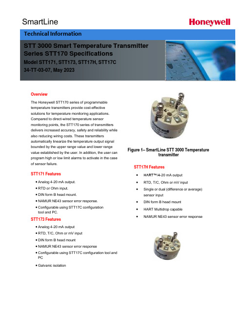
SmartLineOverviewThe Honeywell STT170 series of programmabletemperature transmitters provide cost-effectivesolutions for temperature monitoring applications.Compared to direct-wired temperature sensormonitoring points, the STT170 series of transmittersdelivers increased accuracy, safety and reliability while also reducing wiring costs. These transmittersautomatically linearize the temperature output signalbounded by the upper range value and lower range value established by the user. In addition, the user can program high or low limit alarms to activate in the case of sensor failure.STT171 Features• Analog 4-20 mA output.• RTD or Ohm input.• DIN form B head mount.• NAMUR NE43 sensor error response.• Configurable using STT17C configurationtool and PC.STT173 Features• Analog 4-20 mA output• RTD, T/C, Ohm or mV input• DIN form B head mount• NAMUR NE43 sensor error response• Configurable using STT17C configuration tool and PC• Galvanic isolation Figure 1– SmartLine STT 3000 TemperaturetransmitterSTT17H Features•HART™/4-20 mA output•RTD, T/C, Ohm or mV input•Single or dual (difference or average)sensor input•DIN form B head mount•HART Multidrop capable•NAMUR NE43 sensor error responseSTT 3000 Smart Temperature Transmitter Series STT170 SpecificationsModel STT171, STT173, STT17H, STT17C34-TT-03-07, May 2023Technical InformationDimensions (all models)WiringSTT171 STT173Input:Input:RTD, 2-wire RTD, 3-wire RTD, 4-wire TC, internal CJCRTD,2-wire RTD,3-wire Resistance,2-wire Resistance,3-wireTC, external CJC mV Resistance, 2-wire Resistance, 3-wireOutput:2-wire installationResistance, 4-wireOutput:2-wire installationSTT17HThe STT17C configures the STT171, STT173 and STT17H. The intuitive graphical user interface of the STT17C virtually eliminates the need for operator training after installation on a PC. The STT17C includes all software and transmitter interface hardware necessary to configure the STT171, STT173 and STT17H in non-hazardous work environments.WARNING: The STT17C is not approved for use in Hazardous work environments.System Requirements:Windows® 98SE, ME, 2000 and XP with the following recommendations:Memory: 16 MBDisplay resolution: 800 x 600Hard disk space: 12 MB**or 50%of upper range value,whichever is greater***reference temperature24o COPERATING CONDITIONS APPROVALSAmbient temperature, rated……….……-40 to 85o C (-40 to 185o F)Observed Authority requirements:Standard: Humidity……………………………………0 to 95% RH (non-cond.)EMC 2004/108/EC Vibration…………………………………Max 4g over 25 to 100Hz Emmission and immunity ……… EN 61326ATEX94/9/EC…........................................ EN50014,EN50020, ELECTRICAL INPUT SPECIFICATIONS EN502811-1and EN50284 Supply voltage………………………………8to30VDC FM,ASCN…............................................. 3600,3611,3610Power supply voltage effect………………≤0.005%of span per VDC CSA,CAN/CSA ......................................... C22.2No.157,E60079-11, Warm-up time…………………………..….5min UL913Response time(programmable)…………0.33to60sec Ex/I.S.approval:KEMA06ATEX0042X…………………………II1GD,T80o C…T105o C CURRENT OUTPUT SPECIFICATIONS EEx ia IIC T4.T6Signal output range…………………………4to20mA Max.amb.Temperature for T4….................... 85o CUpdate time………………………………… 135msec Max.amb.Temperature for T6….................... 60o CLoad resistance………....……...…………≤(V supply-8)/0.023A Applicable in zone…..................................... 0,1,2,20,21or220to870οFM,applicable in…………………………………IS,CL I,DIV1,Grp.A-D,T4…T6AEx ia IICALARM LEVELS NI,CL I,DIV2,Grp.A-D,T4...T6 Programmable...................................3.5to4mA downscale Entity,FM Installation Drawing No. (50016324)20 to 23 mA upscale CSA, applicable in.....................................IS,CL I, DIV 1, Grp. A-D, T4...T6 NAMUR NE43 Upscale.........................23 mA Ex ia IIC, AEx ia IIC NAMUR NE43Downscale....................3.5mA Entity,Installation Drawing No... (50016326)Ex/I.S.data:U i (max) .................................................... 30 VDCI i (max)...................................................... 120mADCP i (max) .................................................... 0.84WL i (max)..................................................... 10μHC i (max) .................................................... 1.0 nFUo (max) .................................................. 27 VDCIo (max).................................................... 7 mADCPo (max)................................................... 45m WLo(max) ................................................... 35 mHCo (max) .................................................. 90 nFSTT17H-BN Specification*whichever is greater; Total Reference Accuracy = Basic Accuracy + CJ Accuracy (T/C only)**or 50% of upper range value, whichever is greater*** reference temperature 24o COPERATING CONDITIONS APPROVALSAmbient temperature, rated…………...…. -40 to 85o C (-40 to 185o F) Observed Authority requirements: Standard: Humidity……………………………………0 to 95% RH (non-cond.) EMC 2004/108/EC Vibration…………………………………...…Max 4g over 25 to 100Hz Emmission and immunity ……… EN 61326Cold junction accuracy……………………±1.0o C ATEX94/9/EC… .................................................. EN60079-0,EN60079-15 ELECTRICAL INPUT SPECIFICATIONS Ex / I.S. approval:Supply Voltage....................................8 to 35 VDC KEMA 06 ATEX 0043 X..............................II 3 GD, T80o C...T105o C Power supply voltage effect.................. ≤ 0.005% of span per VDC EEx nA [L] IIC T4. T6 Warm-up time....................................30sec Applicable in zone... (2)Response time(programmable)…………1to60sec Max.amb.Temperature for T4…......................... 85o CGalvanic isolation………………………….1500VAC Max.amb.Temperature for T6…......................... 60o CCURRENT OUTPUT SPECIFICATIONS Vmax (V)Signal output range..................................... 4 to 20 mAUpdate time… ............................................. 440 msecLoad resistance(ν)...................................... ≤(V supply -8)/0.023A0 to 1174 νALARM LEVELSProgrammable…........................................ 3.5 to 4 mA downscale20 to 23 mA upscaleNAMUR NE43 Upscale…......................... 23 mANAMUR NE43Downscale…....................... 3.5 mA9STT 3000 Smart Temperature Transmitter STT171 Custom Configuration Data SheetCustomer P.O. NumberLine ItemModel NumberTag Number (max 15 char)Honeywell Sales Order NumberSensor Type:□Pt100□Ni100□OhmsOutput Values:4 mA Value: 20 mA Value: Response time:□o C□o F□Ohms □o C□o F□Ohms(0.33 – 60 sec)Output Limits:□Span (4 to 20 mA)□Max (3.5 to 23 mA)□Specify Low mA, High mA□NAMUR NE 43 (3.8 to 20.5 mA)Sensor Error Action:□Off□Specify mA□NAMUR NE 43 upscale (23 mA)□NAMUR NE 43 downscale (3.5 mA)10STT 3000 Smart Temperature TransmitterSTT173 Custom Configuration Data SheetCustomer P.O. NumberLine ItemModel NumberTag Number (max 15 char)Honeywell Sales Order NumberSensor Type:□Pt100 □Type B T/C Cold Junction Compensation:□Ni100 □Type E T/C □Internal□Type J T/C □External / Pt100Wiring: □Type K T/C □External / Ni100□2-wire □Type L T/C□3-wire □Type N T/C□4-wire □Type R T/C□Type S T/C□ Ohms □Type T T/C□mV □Type U T/C□Type W3 T/C□Type W5 T/COutput Values:4 mA Value: 20 mA Value: Response time:□o C □o C (1 – 60 sec)□o F □o□mV □mV□Ohms □OhmsOutput Limits:□Span (4 to 20 mA)□Max (3.5 to 23 mA)□Specify Low mA, High mA□NAMUR NE 43 (3.8 to 20.5 mA)Sensor Error Action:□Off□Specify mA□NAMUR NE 43 upscale (23 mA)□NAMUR NE 43 downscale (3.5 mA)STT17H Custom Configuration Data SheetCustomer P.O. NumberLine ItemModel NumberTag Number (max 15 char)Honeywell Sales Order NumberSensor Input:□Single Sensor□Duplex Sensor (Average)□Duplex Sensor (Differential)Sensor Type:□Pt100□Type B T/C Cold Junction Compensation:□Ni100□Type E T/C□Internal□Type J T/C□External / Pt100 Wiring: □Type K T/C□External / Ni100□2-wire□Type L T/C□3-wire□Type N T/C□4-wire□Type R T/C□Type S T/C□Ohms□Type T T/C□mV□Type U T/C□Type W3 T/C□Type W5 T/COutput Values:4 mA Value: 20 mA Value: Response time:□o C□o F□mV □Ohms □o C□o□mV□Ohms(1 – 60 sec)Output Limits:□Span (4 to 20 mA)□Max (3.5 to 23 mA)□Specify Low mA, High mA□NAMUR NE 43 (3.8 to 20.5 mA)Sensor Error Action:□Off□Specify mA□NAMUR NE 43 upscale (23 mA)□NAMUR NE 43 downscale (3.5 mA)Model Selection Guide (34-44-16-07)Model Selection Guides are subject to change and are inserted into the specifications as guidance only.Sales and ServiceFor application assistance, current specifications, pricing, or name of the nearest Authorized Distributor, contact one of the offices below.ASIA PACIFICHoneywell Process Solutions, (TAC) hfs-tac-********************* AustraliaHoneywell LimitedPhone: +(61) 7-3846 1255FAX: +(61) 7-3840 6481Toll Free 1300-36-39-36Toll Free Fax:1300-36-04-70China – PRC - Shanghai Honeywell China Inc.Phone: (86-21) 5257-4568Fax: (86-21) 6237-2826 SingaporeHoneywell Pte Ltd.Phone: +(65) 6580 3278Fax: +(65) 6445-3033South KoreaHoneywell Korea Co LtdPhone: +(822) 799 6114Fax: +(822) 792 9015 EMEAHoneywell Process Solutions,Phone: + 80012026455 or+44 (0)1344 656000Email: (Sales)***************************or(TAC)*****************************AMERICA’SHoneywell Process Solutions,Phone: (TAC) 1-800-423-9883 or215/641-3610(Sales) 1-800-343-0228Email: (Sales)***************************or(TAC)*****************************For more informationTo learn more about Temperature Transmitters,visit Or contact your Honeywell Account ManagerProcess SolutionsHoneywell1250 W Sam Houston Pkwy S Houston, TX 77042Honeywell Control Systems Ltd Honeywell House, Skimped Hill Lane Bracknell, England, RG12 1EB Shanghai City Centre, 100 Jungi Road Shanghai, China 20061 34-TT-03-07May 2023©2023 Honeywell International Inc.。
Honeywell-TB7980温控器安装说明译文
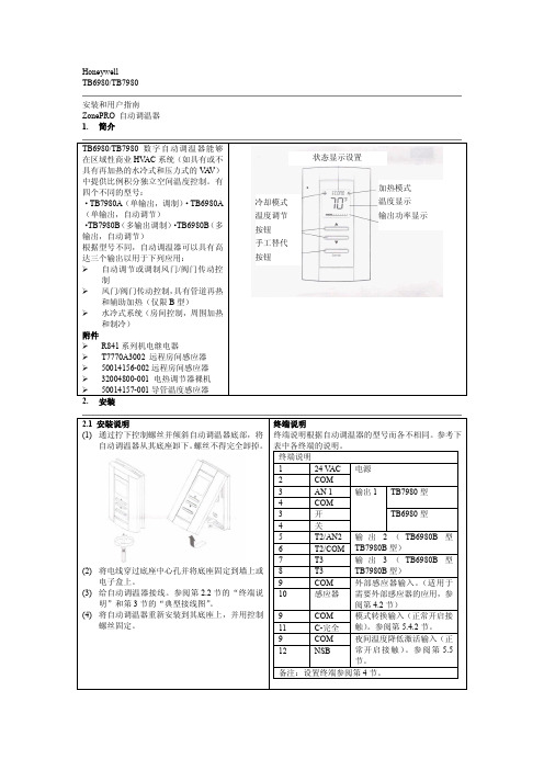
TB6980/TB7980安装和用户指南ZonePRO自动调温器1.简介2.安装2.1安装说明(1)通过拧下控制螺丝并倾斜自动调温器底部,将自动调温器从其底座卸下。
螺丝不得完全卸掉。
(2)将电线穿过底座中心孔并将底座固定到墙上或电子盒上。
(3)给自动调温器接线。
参阅第2.2节的“终端说明”和第3节的“典型接线图”。
(4)将自动调温器重新安装到其底座上,并用控制螺丝固定。
终端说明终端说明根据自动调温器的型号而各不相同。
参考下表中各终端的说明。
终端说明124VAC电源2COM3AN1输出1TB7980型4COM3开TB6980型4关5T2/AN2输出2(TB6980B型TB7980B型)6T2/COM7T3输出3(TB6980B型TB7980B型)8T39COM外部感应器输入。
(适用于需要外部感应器的应用,参阅第4.2节)10感应器9COM模式转换输入(正常开启接触)。
参阅第5.4.2节。
11C-完全9COM夜间温度降低激活输入(正常开启接触)。
参阅第5.5节。
12NSB备注:设置终端参阅第4节。
TB6980/TB7980数字自动调温器能够在区域性商业HVAC系统(如具有或不具有再加热的水冷式和压力式的VA V)中提供比例积分独立空间温度控制。
有四个不同的型号:·TB7980A(单输出,调制)·TB6980A (单输出,自动调节)·TB7980B(多输出调制)·TB6980B(多输出,自动调节)根据型号不同,自动调温器可以具有高达三个输出以用于下列应用:自动调节或调制风门/阀门传动控制风门/阀门传动控制,具有管道再热和辅助加热(仅限B型)水冷式系统(房间控制,周围加热和制冷)附件R841系列机电继电器T7770A3002远程房间感应器50014156-002远程房间感应器32004800-001电热调节器裸机50014157-001导管温度感应器状态显示设置加热模式温度显示输出功率显示冷却模式温度调节按钮手工替代按钮TB7980BTB6980B图1:具有电加热和辅助护壁板加热的风门控制图2:具有电加热和辅助热水加热的风门控制TB7980BTB6980B 图3:具有自动转换、电加热和中央制冷的风门控制图4:新鲜空气供应的温度控制TB7980B TB6980B图5:转换和NSB 输入共用相同的24-Vac 变压器图6:转换和NSB 输入使用不同的24-Vac 变压器风门制动器管加热器继电器模拟护壁板自动定位风门制动器管加热器继电器热阀门正常开启管加热器供应温度感应器空气返回风门制动器管加热器自动转换温度感应器新鲜空气自动定位继电器模拟系统继电器注意:不得共同连到地上注意:不得共同连到地上4.设置4.1配置菜单(参阅下页解释)备注:工厂设置在暗褐色单元格显示。
香蜜温度控制器用户指南说明书
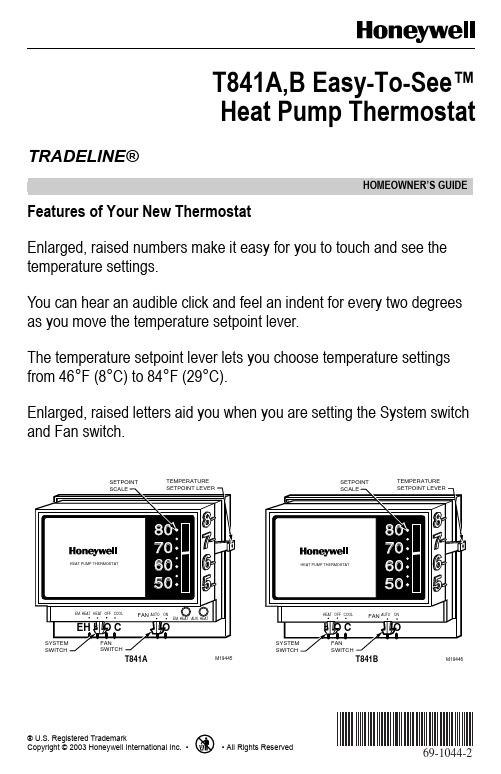
® U.S. Registered TrademarkCopyright © 2003 Honeywell International Inc. • • All Rights Reserved HOMEOWNER’S GUIDE69-1044-2T841A,B Easy-To-See™Heat Pump ThermostatFeatures of Your New ThermostatEnlarged, raised numbers make it easy for you to touch and see the temperature settings.You can hear an audible click and feel an indent for every two degrees as you move the temperature setpoint lever.The temperature setpoint lever lets you choose temperature settings from 46°F (8°C) to 84°F (29°C).Enlarged, raised letters aid you when you are setting the System switch and Fan switch.TRADELINE®69-1044-2 G.H. Rev. 3-03/yourhomeAutomation and Control SolutionsHoneywell International Inc.Honeywell Limited-Honeywell Limitée 1985 Douglas Drive North 35 Dynamic Drive Golden Valley, MN 55422Scarborough, Ontario M1V 4Z9Temperature SelectionTo select the temperature setpoint, slide the lever to the desired point on the setpoint scale. A click is heard and an indent felt every two degrees as the setpoint lever moves. The enlarged, raised 5, 6, 7 and 8 on the right edge of the thermostat provide recognition by touch and sight for the 50°F (10°C), 60°F (16°C), 70°F (21°C) and 80°F (27°C) setpoints.System Switch and Fan Switch SettingsTo select System switch and Fan settings, slide the levers at the bottom of the thermostat base to the desired setting. Enlarged, raised letters on the wallplate and the audible aid click heard at each indent in setting System switch and Fan switch settings.T841A : The large EH, H, O and C are the EM. HT., HEAT, OFF and COOL System switch settings. The large A, O raised letters are the AUTO and ON Fan settings.T841B : The large H, O and C are the HEAT, OFF and COOL System switch settings. The large A, O raised letters are the AUTO and ON Fan settings.NOTE: If the information on this card is desired in Braille, call 1-800-468-1502 for a copy.。
Honeywell CN3240 温控器说明书

ߜ1⁄4DIN SizeߜDual Loop Control ߜPID, Proportional or On/Off ControlߜField Selectable Relay or dc Pulse OutputsߜTimer, 2 SegmentRamp/ Soak and Idle/Run FunctionsߜAutotuning StandardߜOptional RS-232, RS-422, RS-485 Communications ߜ102 mm (4")Mounting DepthߜAluminum Housing ApplicationsߜPlatens and PressesߜFurnaces and OvensߜTemperature ControlPanelsߜExtrudersߜFood ProcessingTimer and EventInput FeaturesIncorporated into the CN3240’sprogrammed control features is abasic timer, configurable inhour/minute increments. The CN3240timer can be used to enable theprocess at a preset time, or disablethe process after a specified amountof time, avoiding the additionalexpense, space requirements andinstallation costs of a separate timer.Most importantly, the CN3240 timerassures you of total compatibility withthe CN3240 process controllerfunctions, requiring only initial setupand minimal operator attention.SpecificationsControl Modes:On/Off,Proportional, and PID-proportionalwith automatic reset (integral)and/or rate (derivative)Control Adjustments:Allparameters independentlyadjustable for each loopModel CN3240$625Basic UnitThe OMEGA®CN3240 Seriestemperature controllerspack the sophisticationand flexibility of twomicroprocessor-basedcontrollers into onecompact 1⁄4DIN package.Two Flexible LoopsEach of the two independent controlloops can be field programmed:Loop #1Loop #2PID T emp. Control PID T emp. ControlPID T emp. Control Overtemp. ControlAlarm/Overtemp Alarm/OvertempTwo sensor inputs (one per loop)can be field programmed as J or Kthermocouple or RTD. The controloutputs are 8 amp relays, fieldchangeable to dc pulse. The relayoutput can be used to directly drivesmall heater loads. In addition, athird 10 Amp relay can be used foralarm control.Dual Input TemperatureControllersWith Timer,Ramp/Soakand Idle/Run FunctionsGKQSS-14U-12thermocoupleprobe, $33,sold separately.See page A-54.P-73Shown smaller than actual size(Specify Model Number)Model Number Price Descriptionyour sales representative for full details when placing an order. OMEGACARE SM covers parts,labor, and equivalent loaners. Comes with complete operator’s manual.Ordering Example: CN3240-4, dual loop temperature controller with digital communications,$625 + 105 = $730. OCW-3 OMEGACARE SM extends standard 1-year warranty toa total of 4 years ($182), $730 + 182 = $912.Pt-129 to 538°C (-200 to 1000°F)±0.10% + 1 digitCN3240 shownwith open doorDual Set Points:Instrument sensorrange, °F or °C, with Ramp/Soakand timer capabilitiesSet Point Limits:Instrumentsensor rangeDeadband:1 to 99°F/1 to 55°CProportional Band:0.1 to 999.9%Automatic Reset:0.00 to 99.99repeats/minuteRate:0 to 500 secondsOutput Cycle Time:0.1 to 60.0 secondsOutput Limit:0 to 100 %Control Outputs:One individualoutput per channelRelay:N.O. contact rated 8 A at120/250 Vac or 5 A at 30 Vdcdc Pulse:Transistor output of20 Vdc at 40 mA, jumper selectableAuxiliary Alarm Output:Non-Latching, normally-energizedor normally de-energized,power-up inhibit featureSetpoint:Sensor spanModes:High or Low AlarmInput Sensor:Channel #1 sensor,channel #2 sensor or both.Relay:N.O. contact rated 10 A at120/250 Vac or 10 A at 30 VdcAuxiliary Event Input:One digitalinput accepts momentary orsustained contact closure, requiringminimum 100 millisecondclosure/openingTimers:00.00 to 99.99 hours,minutes with a “continuous” settingfor soak intervals000.0 to 999.9 Hrs., 0000 to 9999 Hrs.Input Update Rate:600 msec/updateReadout Stability:±1.0°F maximum for every±10°F change ambientInstrument Power:120/230 Vac,50/60 Hz, nominal powerconsumption 10 VA power failuredetection circuitry, watchdog timersOperating environment:0 to 55°C (30 to 130°F) ambienttemperature with relative humidityless than 95%, non-condensingDimensions:Overall:96 x 96 x 121 mm(3.78 x 3.78 x 4.75")Depth Behind Panel:102 mm (4.0")Front Panel Projection:19 mm (0.75")Panel Cutout:92 x 92 mm (3.6 x 3.6")Weight:1.1 kg (2.5 lb)Influence of Line Voltage Variation:±1°F maximum change in readout for±10% nominal line voltageNoise RejectionCommon Mode:Less than ±1°C(2°F) with 230 Vac, 60 Hz appliedfrom sensor input to instrumentcase (with digital filter enabled)Series Mode:Less than ±1°C (2°F)with 100 mV peak to peak. 60Hzseries mode noiseRadio-Frequency Interference(RFI):Typically less than 0.5% ofsensor span at 1 m (3.1') from atransmitter (4 W at 464 MHz)Fieldselectable°F or °CTwo-segmentramp/soakprogramAVAILABLE FORFAST DELIVERY!Open Sensor and Out-of-RangeConditions:Control output adjustablefrom 0 to 100%Digital Communications OptionRS-232-C:Single-drop, IsolatedRS-422, RS-485:Multi-drop, IsolatedCASS-18G-12-DUAL, Dual Element ThermocoupleProbe, $57.50. See page A-76.Female connectorincluded with probe.CANADA www.omega.ca Laval(Quebec) 1-800-TC-OMEGA UNITED KINGDOM www. Manchester, England0800-488-488GERMANY www.omega.deDeckenpfronn, Germany************FRANCE www.omega.frGuyancourt, France088-466-342BENELUX www.omega.nl Amstelveen, NL 0800-099-33-44UNITED STATES 1-800-TC-OMEGA Stamford, CT.CZECH REPUBLIC www.omegaeng.cz Karviná, Czech Republic596-311-899TemperatureCalibrators, Connectors, General Test and MeasurementInstruments, Glass Bulb Thermometers, Handheld Instruments for Temperature Measurement, Ice Point References,Indicating Labels, Crayons, Cements and Lacquers, Infrared Temperature Measurement Instruments, Recorders Relative Humidity Measurement Instruments, RTD Probes, Elements and Assemblies, Temperature & Process Meters, Timers and Counters, Temperature and Process Controllers and Power Switching Devices, Thermistor Elements, Probes andAssemblies,Thermocouples Thermowells and Head and Well Assemblies, Transmitters, WirePressure, Strain and ForceDisplacement Transducers, Dynamic Measurement Force Sensors, Instrumentation for Pressure and Strain Measurements, Load Cells, Pressure Gauges, PressureReference Section, Pressure Switches, Pressure Transducers, Proximity Transducers, Regulators,Strain Gages, Torque Transducers, ValvespH and ConductivityConductivity Instrumentation, Dissolved OxygenInstrumentation, Environmental Instrumentation, pH Electrodes and Instruments, Water and Soil Analysis InstrumentationHeatersBand Heaters, Cartridge Heaters, Circulation Heaters, Comfort Heaters, Controllers, Meters and SwitchingDevices, Flexible Heaters, General Test and Measurement Instruments, Heater Hook-up Wire, Heating Cable Systems, Immersion Heaters, Process Air and Duct, Heaters, Radiant Heaters, Strip Heaters, Tubular HeatersFlow and LevelAir Velocity Indicators, Doppler Flowmeters, LevelMeasurement, Magnetic Flowmeters, Mass Flowmeters,Pitot Tubes, Pumps, Rotameters, Turbine and Paddle Wheel Flowmeters, Ultrasonic Flowmeters, Valves, Variable Area Flowmeters, Vortex Shedding FlowmetersData AcquisitionAuto-Dialers and Alarm Monitoring Systems, Communication Products and Converters, Data Acquisition and Analysis Software, Data LoggersPlug-in Cards, Signal Conditioners, USB, RS232, RS485 and Parallel Port Data Acquisition Systems, Wireless Transmitters and Receivers。