拖拉机组装
Ultra-Tow 车辆拖拉机安装说明书
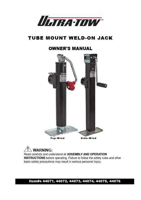
TUBE MOUNT WELD-ON JACKOWNER’S MANUALTo p-W i n d S i d e-W i n dWARNING:Read carefully and understand all ASSEMBLY AND OPERATION INSTRUCTIONS before operating. Failure to follow the safety rules and other basic safety precautions may result in serious personal injury.Thank you very much for choosing an Ultra-Tow product! For future reference, please complete the owner’s record below:Model: _______________ Purchase Date: _______________Save the receipt, warranty and these instructions. It is important that you read the entire manual to become familiar with this product before you begin using it.This jack is designed for certain applications only. The distributor cannot be responsible for issues arising from modification. We strongly recommend this jack not be modified and/or used for any application other than that for which it was designed. If you have any questions relative to a particular application, DO NOT use the jack until you have first contacted the distributor to determine if it can or should be performed on the product.For technical questions please call 1-800-222-5381.INTENDED USEThis top-quality Ultra-Tow™ trailer jack has a weld-on style mount that includes a male matingpipe/tube and a pin and lanyard assembly. The round tube jacks have a corrosion-resistantexterior-grade black powder-coat finish on the outside, with a zinc finish on the inner tube and foot. The square tube jacks have a durable exterior-grade black paint finish on the outside tube with zinc finish on the inner tube. The topwind models (Item#s 44071, 44072, 44073 and 44075) have a red claw knob on a clear zinc solid bar handle that folds away when not in use. The sidewind models (Item#s 44074 and 44076) have a large, comfortable grooved handle that makes cranking almost effortless. A grease zerk fitting is built in for easy greasing of the jack, and a welded-on foot adds stability.GENERAL SAFETY RULESWARNING∙Read and understand all instructions. Failure to follow all instructions listed below may result in serious injury.∙Owner must ensure that the jack is installed according to these instructions∙Never position any part of body under this product or supported load.∙Fully retract/rotate jack before towing.∙This jack is not intended for use as a transport device. Minimize movement of the implement while the jack is under load.∙Do not allow children to play on or around this jack while supporting a load.∙Secure the load, vehicle and trailer form rolling when operating jack.∙Never attempt to lift or support loads in excess of the rated strength of this trailer jack.∙This jack is designed for vertical loading. Excessive side forces may cause failure and or injury.∙Before moving trailer crank jack to its lowest position.∙These jacks are not designed for round tongues.∙Do not modify the jack in any way. Unauthorized modification may impair the function and/or safety and could affect the life of the equipment. There are specific applications for which thejack was designed.∙The swivel is very strong. However abuse, corrosion or damage may cause swivel to break.Regularly inspect the swivel for damage and discontinue use if the swivel is damaged.∙Store idle jack. When jack is not in use, store it in a secure place out of the reach of children.Inspect it for good working condition prior to storage and before re-use.SAVE THESE INSTRUCTIONSASSEMBLYWeld shownOPERATION1. To activate the swivel function on the jack pull the pin and swivel jack into desired position.2. Only swivel jack when trailer is securely attached to a tow vehicle. Make sure pull pin is properlyengaged after swiveling into desired position.3. Make sure swivel pull pin is properly engaged after swiveling into desired position. MAINTENANCE•Maintain your Jack. It is recommended that the general condition of any jack be examined before it is used. Keep your jack in good repair by adopting a program of conscientious repair and maintenance. If jack is damaged, discontinue use of the jack.•This jack is pre-greased for easy operation. This jack however includes a grease zerk for easy lubrication as needed.WARRANTY3-year limited warrantyDistributed byNorthern Tool + Equipment Co., Inc.Burnsville, Minnesota 55306Made in China。
谈小型拖拉机离合器的拆卸与装配
谈小型拖拉机离合器的拆卸与装配作者:高丽茹来源:《农机使用与维修》2017年第03期摘要:为保证拖拉机离合器修理后的装配质量及使用性能,详细地介绍了小型拖拉机离合器拆卸与装配技术要点。
关键词:小型拖拉机;离合器;拆卸;装配中图分类号:S220.3文献标识码:Adoi:10.14031/ki.njwx.2017.03.045离合器在长期使用中,因自然磨损和使用操作不当造成的故障,如使用过程中出现的离合器打滑、分离不彻底,通过调整保养不能解决问题时,就要进行拆卸修理。
拆卸与装配技术的好坏决定了离合器修后的使用寿命,不可忽视。
为保证小型拖拉机离合器修理后的装配质量及使用性能,现将其拆卸与装配中注意事项说明如下:1离合器的拆卸(1)为了保证离合器与飞轮整体的动平衡,确保安装时的准确位置,离合器拆卸前,应注意飞轮和离合器盖、平衡片与离合器盖的相互位置,在飞轮和离合器盖上用冲头等工具凿上对合标记,以保证装复时能够按原来位置装回。
因为离合器总成在出厂前进行过动平衡和静平衡测试,通过钻孔去重和加添平衡片,使不平衡量在允许范围内。
如装复不注意,就会破坏离合器工作的平衡性,缩短曲轴和传动系的使用寿命。
(2)拆卸离合器盖总成,在导向轴承内插入导向专用工具,使用工具按对角方向逐渐拧松并拆下紧固螺栓,取出离合器压盘总成。
注意:不要将润滑油或润滑脂沾到压盘的摩擦表面。
(3)拆卸离合器从动盘时,注意不要将润滑油或润滑脂沾到从动盘摩擦片的摩擦表面。
2装配前的检查(1)用柴油将分离轴承及壳内的60204和60206轴承清洗干净后,用一只手紧捏住轴承内圈,另一只手握住外圈,沿其轴向推拉,若是感到轴向旷动量很大,则说明轴承磨损过甚,应更换;反之可继续使用。
将轴承浸入熔化了的黄油(2号钙基润滑脂)中,直到黄油渗满轴承,待黄油冷却后,将轴承取出即可装配。
(2)用汽油或煤油清洗从动盘后,若摩擦片仅有轻微烧蚀,可用锉刀锉平;若从动盘总成磨损后的厚度小于9 mm(标准厚度为10±0.3 mm),或摩擦片烧毁、破裂,应更换新摩擦片。
割草机组装方法
割草机组装方法
嘿,朋友们!今天来和大家聊聊割草机组装方法。
组装割草机其实并不复杂啦!首先呢,你得把各个部件都准备好,可别少了啥东西哟!然后就是安装轮子,这就好比给人穿上合适的鞋子,得稳稳当当的呀!接着安装把手,就像给机器安上了手臂,得方便操作不是。
再把发动机安装好,这可是核心呀,可不能马虎!安装刀片的时候要小心哦,那可是很锋利的,就像老虎的牙齿一样。
还有各种线路啥的,都得接好,不能弄错啦!在组装的过程中,一定要仔细再仔细,每个螺丝都要拧紧,不然跑着跑着散架了可咋办哟!
在这个过程中,安全性那是超级重要的呀!就像走钢丝一样,稍不注意就可能出问题。
稳定性也不能忽视,要是摇摇晃晃的,怎么能好好工作呢?所以一定要确保每个部件都安装到位,螺丝拧紧,线路接好,这样才能保证割草机在工作的时候既安全又稳定呀!
割草机的应用场景那可多了去了!无论是在大草坪上,还是在小院子里,它都能大显身手。
它的优势也很明显呀,能快速高效地把草割得整整齐齐的,可比我们自己用镰刀割草轻松多了,这不就像有了个小助手帮我们干活一样嘛!
我就知道有个例子,隔壁老王家的院子很大,以前他自己割草,累得够呛还弄不好。
后来买了个割草机,自己组装好,嘿,没一会儿功夫就把院子收拾得干干净净的。
他可高兴坏了,直夸割草机好用呢!
所以呀,割草机组装并不难,只要我们认真对待,注意安全和稳定,它就能成为我们的好帮手,让我们的草坪变得美美的哟!割草机真的超棒的呀!。
关于拖拉机半轴装配技术的

通过合理的装配工艺和严格的检验流程,可以确保 半轴安装的质量,从而降低拖拉机运行中的安全隐 患。
延长使用寿命
正确的装配方法和合适的润滑措施可以减少半轴与 其它部件的磨损,从而延长拖拉机各部件的使用寿 命。
装配技术的历史与发展
历史
拖拉机半轴装配技术随着拖拉机产业的发展而不断进步,早期的半轴装配主要 依靠人工操作,随着技术的进步,自动化设备逐渐应用于半轴的加工和装配过 程。
零件定位与紧固
定位
在装配过程中,需要使用定位工具或定位方法,如使用定位销、键、过盈配合等,将零件准确地固定在正确的位 置上。定位可以确保装配位置的准确性,并避免零件在装配过程中移动或错位。
紧固
在零件定位后,需要对其进行紧固,以使其保持在正确的位置上并承受工作载荷。紧固可以通过螺栓、螺母、铆 钉等紧固件来实现,紧固过程中需要控制紧固力矩,以确保紧固件不会过紧或过松,从而保证装配质量和安全性 。
装配技术的优化方向
提高装配精度
通过采用高精度的测量设备和 严格的装配工艺流程,提高半 轴装配的精度,确保半轴组件 之间的配合精度,从而提高半 轴的性能和使用寿命。
减少装配时间
通过优化装配工艺和流程,减 少半轴装配所需的时间,提高 生产效率,降低生产成本。
自动化装配
应用自动化设备和技术,实现 半轴组件的自动抓取、定位和 组装,减少人工干预,提高装 配的一致性和稳定性。
04
拖拉机半轴装配技术的应用与优化
装配技术的应用范围
农业领域
拖拉机是农业领域中重要的机械设备 ,半轴装配技术广泛应用于各种类型 的拖拉机,如轮式和履带式拖拉机, 用于驱动车辆的行驶和作业。
工业领域
在工业领域,拖拉机半轴装配技术也 得到了广泛应用,如物料搬运、矿山 作业、建筑工地等场所,半轴装配技 术为车辆提供稳定、高效的驱动力。
汽车拖拉机拆装指导
资料范本本资料为word版本,可以直接编辑和打印,感谢您的下载汽车拖拉机拆装指导地点:__________________时间:__________________说明:本资料适用于约定双方经过谈判,协商而共同承认,共同遵守的责任与义务,仅供参考,文档可直接下载或修改,不需要的部分可直接删除,使用时请详细阅读内容汽车拖拉机拆装实习指导书目录1、拆装实习注意事项2、实习任务书3、实习考核要求4、实习报告要求5、汽车拖拉机拆装实习前准备6、第一部分发动机的拆装与检测7、第二部分汽车拖拉机底盘的拆装与检测8、第三部分汽车拖拉机电器设备的拆装与检测9、汽车拖拉机拆装实习思考题汽车拖拉机拆装实习注意事项1、拆装实习前,应仔细阅读本实习指导书,要求大体了解该实习部分的结构和工作原理,并研究拆装的方法,做好工具和场地的准备。
2、拆装前应大体清理所拆部件的外表,并注意场地和人员的清洁。
精密零件要妥善排放,以免碰伤,有配合表面的应配对放置。
如有安装方向性和顺序要求的零部件,拆装前均要做好记号,以免安装时出错。
3、进行实习时必须事先熟悉仪器设备的性能、操纵方式和注意事项,多人合作进行的项目,则应事先协调好,保证作业时有条不紊。
4、在工具的选用上应尽可能使用标准或专用工具,无特殊情况不许用通用工具,如活扳手。
5、在实习全过程中应贯彻“安全第一”的原则:1)严禁在无指导教师允许情况下使用汽油和柴油,更坚决禁止在实习现场吸烟或使用明火(包括电火花);2)严禁在无教师指导的情况下动用电动设备;3)在吊放大型汽车拖拉机部件时应保证捆系牢靠、排放稳定可靠,并要求在实习教师现场指导下完成;6、在每个工作时段(如上、下午)结束后,应保持现场清洁,工具和零部件摆放清洁有序,并核对工具数目。
7、学生要严格遵守作息时间,不允许迟到早退,有事要请事假,超过半天需学院签字批准。
实习报告要求1、分析你所拆发动机的结构特点,记录主要实习数据如气缸上下部位缸径、曲轴主轴直径、曲柄销直径、活塞头部及裙部直径,实习过程中的体会与收获;2、分析你所实习的汽车拖拉机底盘部件的结构特点,记录主要实习数据例如轮胎轮径和气压、轮鼓内外径、离合器自由间隙、轮距、轴距、变速器的类型及工作原理、离合器的工作原理与调整、主减速器的调整、制动器的工作原理与调整、转向系的工作原理与调整,实习过程中的体会与收获;3、分析你所实习的汽车拖拉机全车电路与电器部件的工作原理图,记录主要实习数据如畜电池电压、不同点火方式比较、火花塞间隙调整、分电器触点间隙调整、喇叭音量分贝、发电机输出电压及控制、电起动机启动扭矩测试、电控系统测试与诊断、照明信号仪表电路检测、空调系统原理与检测,实习过程中的体会与收获;实习考核方式成绩考核由三部分内容组成:平时考勤30%(缺席0分,迟到早退60分,病事假80分),学生自评10%(优、良、中、及格、不及格),实习报告30%(百分制),实习中实作能力及表现30%(根据回答问题情况打分)。
重庆农用机械衬套的组装办法有哪些,你知道吗
重庆农用机械衬套的组装办法有哪些,你知道吗引言重庆在农业机械领域已经取得了不少进步,农用机械衬套是机械设备中十分关键的部件。
衬套的质量直接影响到机械设备的性能和寿命,因此正确安装衬套也是保持机械设备正常工作的关键步骤。
在这篇文章中,我们将讨论一些重要的组装办法,以确保你正确地安装农用机械衬套。
常见衬套组装办法1.冷装法(直接冷装)这种办法通常适用于衬套和配合孔尺寸相同的情况。
直接将衬套用力套入孔内,然后利用冷缩力将衬套固定在孔内。
在孔与套之间涂上适当的紧固剂能加强固定。
2.热装法(直接热装)这种办法适用于衬套和配合孔尺寸差异较大的情况,可利用膨胀原理和热缩力将衬套固定在配合孔内。
首先将衬套置于配合孔内,然后利用火炬或火箭枪等知用工具使衬套受热膨胀,使其挤压入配合孔内,并紧绷在配合孔轮廓上。
等到衬套冷却时就能和孔搭配完美。
3.冷卸法(直接冷卸)通过传统的机械拆卸工具,如多功能扳手、钳子、冲击器等工具对衬套进行卸下,这种方法不易伤害到整个机械设备,卸载效率高,是日常维修常用的方法。
4.液氮收缩法(低温装配)这种办法适用于衬套和配合孔尺寸相差较大的情况,衬套用力套进孔内后,在衬套内部排出所有空气,再将整个安装部位溶在液氮中,当衬套和液氮一起降温时,会出现一种收缩效应,通过这种方式可以将衬套强行收缩进配合孔内。
5.涂覆法(涂层配套)这种办法适用于公差较大的配件。
在配合孔外表面组织一层厚度适当的特殊材料,使其与衬套配合孔形成一定的压合,从而达到衬套固定的效果。
结论以上便是农用机械衬套的常见组装办法,不同的方法适用于不同的情况,正确选择和使用会对机械设备性能和寿命产生非常大的影响。
我们在实际操作时,选择合适的组装办法,是保持机械设备性能长期稳定的绝对关键一步。
洛阳一拖东方红拖拉机重托车间生产流程
洛阳一拖东方红拖拉机重托车间生产流程1.零部件供应:首先,车间会与各个零部件供应商签订合作协议,以确保原材料的及时供应。
这些供应商会提供各种零部件,如发动机、轮胎、传动系统等。
2.组件制造:一旦零部件到达车间,就会按照生产计划进行组装。
首先是各个零部件的检验和质量控制。
然后将符合要求的零部件组装为组件,如发动机组件、底盘组件等等。
3.装配线生产:在组件制造完成后,它们会被送到装配线上进行后续的整车装配。
在装配线上,工人会根据产品规范和流程图,逐步将各个组件组装成最终的拖拉机产品。
这一过程需要严格的质量控制,以确保每个车辆的质量符合标准。
4.质检和测试:在装配完成后,拖拉机会被送到质检区,进行最后的质量检验。
质检员会对拖拉机进行外观检查、功能测试、性能测试等,确保各项指标都符合要求。
5.喷涂和烘干:通过质检后,拖拉机会被送到喷涂区进行喷涂。
拖拉机会经过喷涂工艺,包括底漆、面漆等,以增加其防腐和美观性能。
之后,喷涂完成的拖拉机将被送入烘干室进行烘干处理。
6.最终组装和调试:经过喷涂和烘干后,拖拉机将进一步进行最终组装和调试。
这一过程包括安装驾驶室、安装电气系统、调试传动系统等。
完成后,拖拉机将进行最终的检查,确保每个细节都符合标准。
7.整车测试:在最终组装和调试完成后,拖拉机会进行整车测试。
这包括静态测试和动态测试。
静态测试测试拖拉机的各项功能和性能,动态测试测试拖拉机在不同工况下的工作表现。
8.包装和出厂:完成整车测试后,拖拉机将进行最后的包装工作。
这包括使用适当的包装材料对拖拉机进行保护,并在包装上标注相关信息。
最后,拖拉机将被出厂,准备发往销售网点或直接向客户交付。
以上就是洛阳一拖东方红拖拉机重托车间的生产流程。
通过每个环节的精心组织和严格控制,一台高质量的拖拉机能够顺利生产出来。
这个流程中每个环节的质量和效率都非常重要,以确保产品的品质。
久保田拖拉机安装指南说明书
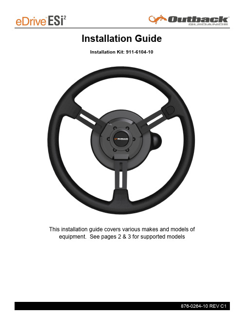
Installation GuideInstallation Kit: 911-6104-10 Array This installation guide covers various makes and models of equipment. See pages 2 & 3 for supported models2WD/MFWD Tractors:Case IHVersatile John Deere New Holland6100 6105M 6110 6110M 6115M 6120 6120M 6125M6130 - Standard 6130M 6140M 6145M 6150M 6155M 6170M 6175M 6195M 6200 6210 62206230 - Standard 6300 6310 63206330 - Standard 6400 6410 64206430 - Standard 65206534 - Premium 6600 6610 6620 6800 6810 6820 6910 69207130 - Standard 7200 7200R 7210 7210R 7215R 72207230 - Standard 7230R 7250R 7260R 7270R 7280R 7290R 7310R 73207330 - Standard 7400 7410 74207430 - Standard 7510 7520 7600 7610 7630 7700 7710 7720 7730 7800 7810 7820 7830 7920 7930 8100 8110 8120 8130 8200 8210 8220 8225R 8230 8235R 8245R 8260R 8270R 8285R 8295R 8300 8310 8310R 8320 8320R 8330 8335R 8345R 8360R 8370R 8400 8400R 8410 8420 8430 8520 8530Maxxum 100 Maxxum 110 Maxxum 115 Maxxum 120 Maxxum 125 Maxxum 130 Maxxum 135 Maxxum 140 Maxxum 145 Maxxum 150 MXU100 MXU110 MXU115MXU115 ValueMXU125MXU130 Value MXU135 Optum 270 Optum 300 Puma 115 Puma 125 Puma 130 Puma 140 Puma 145 Puma 150 Puma 155 Puma 160 Puma 165Puma 170 Puma 175 Puma 180 Puma 185 Puma 195 Puma 200 Puma 210 Puma 215 Puma 220 Puma 225 Puma 230 Puma 240 Puma 240295 310 315 335 360175195210260 265 290T6.120 T6.140 T6.145 T6.150 T6.155 T6.160 T6.165 T6.175 T6.180 T6020 T6030 T6040 T6050 T6060 T6070 T6080 T7.170 T7.175 T7.185 T7.190 T7.200T7.210 T7.220 T7.230 T7.235 T7.245 T7.250 T7.260 T7.270 T7.290 T7.315 T7030 T7040 T7050 T7060 T7070 TS100A TS110A TS115A TS125A TS130A TS135AKubota M8-191 M8-211Articulated Tractors:Versatile John Deere Swathers:Combines:John DeereJohn Deere 350 375* 400* 500+ 500DT 520 520DT550 550DT 570 570DT 575+ 610 610DT9100 9120 9200 9220 9230 9300 9320 9330 9360R9370R 9410R 9420 9420R 9430 9460R 9470R 9470RX 9510RW235 W260S560 S660 S670 S680 S690 S760S770 S780 S790 T550* T560* T660*T670* W540* W550* W650* W660** first 3 digits of serial number must be 307 or higher + 2012 and newer models* 2012 and newer modelsTrack Tractors:8100T 8110T 8120T 8200T 8210T 8220T 8230T 8230T 8295RT 8300T 8310RT 8310T8320RT 8330T 8335RT 8345RT 8360RT 8370RT 8400T 8410T 8420T 8430T 8520T 9300T9320T 9400T 9420T 9430T 9460RT 9470RT 9510RT 9520RT 9530T 9560RT 9570RT 9630TJohn Deere9520R 9520RX 9530 9560R 9570R 9570RX 9620R 9620RX 9630IntroductionThe procedures outlined in this guide provide the basic installation procedure for the ESi2 on the machines specified on the front cover of this guide. If you do not see your machine listed, contact customer support for further instruction. The kit components and corresponding install instructions are designated for each applicable machine make and model and may not be used on undesignated machine models.Review Installation Kit ContentsKit contents are outlined in the ESi2 installation section on pages 10 and 11. Read all applicable installation instructions for your machine’s model and ensure that all required kit components are present before beginning the installation.NOTE: Due to manufacturing processes outside of Outback Guidance’s control, the installer may have to adapt this kit to your distinct situation.Read and Follow All Safety Messages• Refer to the safety manual for the machine that the ESi2 is being installed on for operating age and precautions.• Prior to installing and operating the ESi2, read and understand all safety precautions as outlined in this guide• Store this guide and all related safety information with related machine manuals for future reference.Safety Information and Warnings*• ESi2 is NOT designed to replace the machine’s operator and is designed as a driving aid for use in precision agriculture applications.• ESi2 is NOT intended for use on roadways and should remain disengaged at all times when traveling on roadways.• ESi2 does NOT control the speed of the machine and a human operator is required to manually maintain a safe operating speed.• ESi2 does NOT avoid obstacles. To prevent human, machine and property injury a human operator is required to operate the machine at all times.• Do NOT allow anyone to operate without instructions.• At all times the driver is fully responsible for the safe operation of the vehicle.* The safety warnings contained in this installation guide are not meant to be an exhaustive list of potential hazards.Introduction• To ensure peak performance, ESi2 should only be installed after a thorough machine inspection has been conducted. The contents of this kit and ESi2 are not intended toreplace preventative and or needed maintenance. To avoid bodily and machine injury,follow the machine preparation checklist below:⇒ Inspect steering linkage: Machine should drive in a straight line without manual correction⇒ Turn off machine and power-off all electronic gauges, monitors and external devices when installing or performing maintenance on the ESi2⇒ Park machine on a clean and level surface⇒ Lower all implements and headers to the ground⇒ Apply the parking break and chock wheels⇒ Inspect any drilling and/or cutting sites to ensure no electrical wiring damage will be incurredInstall #1John Deere R series TractorsFor machine specific installation instructions start at page 8.Install #2John Deere Combines and SwathersFor machine specific installation instructions start at page 14.Install #3John Deere 7000, 8000 & 9000 series tractorsFor machine specific installation instructions start at page 20.Install #4John Deere Tractors with Left -Hand reversersFor machine specific installation instructions start at page 26.Install Guide IndexThis installation guide covers multiple machine types. Refer to the index below to find the section that applies to your machine.Install #5John Deere 6000, 6000M, and 7000 2WD/MFWD tractors For machine specific installation instructions start at page 32.Install #6Case IH and New Holland 2WD/MFWD tractorsFor machine specific installation instructions start at page 38.Install #7Versatile MFWD & Articulated TractorsFor machine specific installation instructions start at page 44.Install #8Versatile Nemesis and Kubota M8 MFWD TractorsFor machine specific installation instructions start at page 50.SAVE the nut as it will be used later in this installation.Remove the telescoping actuator knob and metal actuators to gain access to thenut that holds the steering wheel onto theRemove and SAVE this nut as it will be used later in this installation.Following the manufacturer’s recommended procedure remove the steering wheel.NOTE: Consult your equipment dealer if you are unsure of the correct procedure for removing the steeringwheel.Steering column is ready for ESi2 installation.ESi2 wheel successfully installed. Continue to page 49 to complete theinstallation.Remove the steering wheel center cap and the nut holding the telescoping actuator knob on the shaft.SAVE the nut as it will be used later in this installation.Remove and SAVE the nut that holds the steering wheel onto the shaft as it will be used later in this installation.Following the manufacturer’s recommended procedure remove the steering wheel.NOTE: Consult your equipment dealer if you are unsure of the correct procedure for removing the steering wheel.Remove the telescoping actuator knobshaft.Save the actuator plates as they will be used later in this installationSteering column is ready for ESi2 installation.ESi2 wheel successfully installed. Continue to page 49 to complete theinstallation.Install #3John Deere 7000, 8000 & 9000 series tractorsRemove the steering wheel center capand the nut holding the telescoping actuator knob on the shaft.SAVE the nut as it will be used later in this installation.Remove the telescoping actuator knoband actuator plates to gain access to thenut that holds the steering wheel onto the shaft.Remove and SAVE this nut as it will beused later in this installation.Following the manufacturer’srecommended procedure remove thesteering wheel.NOTE: Consult your equipment dealerif you are unsure of the correct procedure for removing the steering wheel.Steering column is ready for ESi2 installation.ESi2 wheel successfully installed. Continue to page 49 to complete theinstallation.Remove the steering wheel center cap and the nut holding the telescoping actuator knob on the shaft.SAVE the nut as it will be used later in this installation.Remove the telescoping actuator knob and actuator plates to gain access to the nut that holds the steering wheel onto the shaft.Remove and SAVE this nut as it will be used later in this installation.Following the manufacturer’s recommended procedure remove the steering wheel.NOTE: Consult your equipment dealer if you are unsure of the correct procedure for removing the steering wheel.Steering column is ready for ESi2 installation.ESi2 wheel successfully installed. Continue to page 49 to complete theinstallation.Remove the steering wheel center capand the nut holding the telescopingactuator knob on the shaft.SAVE the nut as it will be used later in thisinstallation.Remove and SAVE the nut that holds thesteering wheel onto the shaft as it will beused later in this installation.Following the manufacturer ’srecommended procedure remove thesteering wheel.NOTE: Consult your equipment dealerif you are unsure of the correctprocedure for removing the steeringwheel.Remove the telescoping actuator knoband actuator plates to gain access to thenut that holds the steering wheel onto theshaft.Save the actuator plates as they will beused later in this installationSteering column is ready for ESi2 installation.ESi2 wheel successfully installed. Continue to page 49 to complete theinstallation.Remove the steering wheel center capand the nut holding the telescoping actuator knob on the shaft.SAVE the nut as it will be used later inthis installation.Remove the telescoping actuator knob to gain access to the nut that holds the steering wheel onto the shaft.Remove and SAVE this nut as it will be usedlater in this installation.Following the manufacturer’s recommendedprocedure, remove the steering wheel.NOTE: Consult your equipment dealerif you are unsure of the correct procedure for removing the steeringwheel.Steering column is ready for ESi2 installation.ESi2 wheel successfully installed. Continue to page 49 to complete theinstallation.Remove the steering wheel center capand the nut holding the telescoping actuator knob on the shaft.SAVE the nut as it will be used later inthis installation.Remove and SAVE this nut as it will be usedlater in this installation.Following the manufacturer’s recommendedprocedure, remove the steering wheel.NOTE: Consult your equipment dealerif you are unsure of the correct procedure for removing the steeringwheel.Steering column is ready for ESi2 installation.ESi2 wheel successfully installed. Continue to page 49 to complete theinstallation.Install #8Versatile Nemesis and Kubota M8 MFWD TractorsRemove the steering wheel center capand the nut holding the telescopingactuator knob on the shaft.SAVE the nut as it will be used later inthis installation.Remove the telescoping actuator knob togain access to the nut that holds thesteering wheel onto the shaft.Remove and SAVE this nut as it will be usedlater in this installation.Following the manufacturer’s recommended procedure, remove the steering wheel.NOTE: Consult your equipment dealerif you are unsure of the correctprocedure for removing the steeringwheel.。
- 1、下载文档前请自行甄别文档内容的完整性,平台不提供额外的编辑、内容补充、找答案等附加服务。
- 2、"仅部分预览"的文档,不可在线预览部分如存在完整性等问题,可反馈申请退款(可完整预览的文档不适用该条件!)。
- 3、如文档侵犯您的权益,请联系客服反馈,我们会尽快为您处理(人工客服工作时间:9:00-18:30)。
潍坊天鸿农业装备有限公司年产1.5万台拖拉机生产项目
项目建议书
二〇一〇年二月
一、项目名称
年产1.5万台拖拉机生产项目
二、项目建设地址
该项目位于滨海经济开发区科技项目区。
三、项目建设单位概况
潍坊天鸿农业装备有限公司是专门从事农业装备的研究开发及生产的贸易企业,企业性质为有限责任公司。
公司自成立至今,随着产品的销量逐年攀升,公司的市场份额不断扩大。
公司所有的设备都是根据用户的专门应用而特别设计的﹐气动葫芦、气动平衡吊、助力机械手和吊具再配合导轨特别地设计成一台整合设备,配合流水线为客户提供整体解决方案。
我们采用一个基本的起吊设备型号,根据所需的吊具形式、产品重量和生产布局来设计。
历经十余年的努力拼搏,公司在全国同行业中异军突起,快速成长。
随着市场需求的不断增加,经营规模的不断扩大,在产品的技术含量、产品安全、产品环保、市场占有率方面居行业前列。
四、项目提出的背景
国际金融危机对我国装备制造业造成了一定影响。
2008年机械行业统计口径内的装备制造业工业总产值、出口增速同比分别回落了8.6个、15.2个百分点。
为了振兴我国装备制造业,2009年2月4日国务院审议并原则通过了装备制造业调整振兴规划。
温家宝总理在政府工作报告中也专门提出,落实自主研发重大装备国内依托工程和政府采购制度,着力发展重大成套设备、高技术装备和高技术产业所需装备,提高装备制造业集成创新和国产化水平。
“大力振兴装备制造业”,是十六大报告提出的“走新型工业化道路”战略举措之一。
政策的提出加工行业的发展提供了市场条件。
该项目主要生产农用车。
政策的提出为项目的实施提供了有力的政策支持,也为项目产品提供了广阔的市场空间,项目建成后,直接为农用车提供机械零部件,解决产品的销路问题,也极大的促进了我国工程机械行业乃至装备制造业的发展。
在此背景下潍坊天鸿农业装备有限公司提出拖拉机生产项目。
五、项目建设必要性
1、符合国家的产业政策
装备制造业是为国民经济各行业和国防建设提供技术装备的战略性、基础性产业,行业门类广,关联作用大,吸纳就业能力强。
在当前为应对国际金融危机和拉动内需,振兴装备制造业已成为国务院加快发展的主要产业之一,装备制造业振兴规划纲要已报国务院审议原则通过。
振兴规划出台非常适时,为我国制造装备业发展提供强有力的政策支持。
本次装备制造业调整振兴规划,其立足点鲜明地直指金融危机背景下产业的健康发展,并明确了方向性和政策性的调整方案,更加突出地强调提高自主创新能力、提高基础配套水平及推进企业兼并重组扶优扶强等措施。
目前,相关重大项目、首台(套)设备的申报工作也已经全面铺开。
反应速度之快,执行力度之强,达到前所未有。
当前,尽管受金融危机的影响,装备制造业增幅有所下降,而在政策层面工程机械行业却利好频现。
先是国家出台了“4万亿”投资计划,紧接着装备制造业调整振兴规划也迅速登台,接连两道文件重拳出击,给工程机械行业的发展策马扬鞭。
透过这份工程机械制造业三年振兴规划要点,工程机械企业将会对振兴规划获得更为清楚的认知。
2、符合装备制造业调整和振兴规划
装备制造业是为国民经济各行业提供技术装备的战略性产业,产业关联度高、吸纳就业能力强、技术资金密集,是各行业产业升级、技术进步的重要保障和国家综合实力的集中体现。
为应对国际金融危机的影响,落实党中央、国务院关于保增长、扩内需、调结构的总体要求,确保装备制造业平稳发展,加快结构调整,增强自主创新能力,提高自主化水平,推动产业升级,特编制装备制造业调整和振兴规划实施细则,作为装备制造业综合性应对措施的行动方案。
规划期为2009-2011年。
规划目标中指出:基础件制造水平得到提高,通用零部件基本满足国内市场需求,关键自动化测控部件填补国内空白,特种原材料实现重点突破。
该项目的提出为实现规划目标做出一定的贡献。
3、促进相关产业发展,拉动经济增长,经济发展的需要
装备制造业与建筑业、建材、冶金、纺织、化工、机械、仪表等50多个物质生产部门紧密相关,尤其是对钢材等原材料的需要,原材料以及成品的运输,进而能够大大拉动相关产业的发展。
因此,装备制造业能带动相关产业发展的新的经济增长点。
因此,该项目的开发建设将极大地促进相关产业的发展,拉动地方经济增长。
4、是增加当地就业机会,推动区域经济快速发展的需要
项目需新增劳动定员共170人,能够在一定程度上缓解当地的就业压力,为群众创造更多的经济价值。
该项目的建立还能在无形之中加强相关产业之间的联系,推动区域乃至潍坊市的经济发展,经济的向前发展能起到稳定社会使政府各职能部门跟有效的进行宏观调控,有利于社会主义和谐社会的建立。
综上所述,该项目的建设不仅符合国家产业政策,而且对滨海经济开发区的经济发展产生巨大的拉动作用。
因此,该项目的开发建设是十分必要的。
六、项目占地面积及建设内容
该项目拟建于滨海经济开发区科技项目区,占地100亩,新建综合办公楼,职工公寓楼、生产车间、仓库、附属用房等建构筑物,新上生产设备若干台,预计一年半时间建成。
项目建设内容详见下表
七、主要生产设备
变速箱生产线两台、拖拉机组装线三条、辅助设备20余台。
八、主要工艺流程简介
构件→组装→成型
九、投资及资金筹措
该项目总投资12055万元,其中,固定资产费用10555万元,铺底流动资金1500万元,固定资产中建筑工程费4217万元,设备购置及安装费3888万元,工程建设其他费用1947万元,预备费503万元。
项目建设资金全部由企业自筹解决。
十、能耗分析
1、电
该项目设备总装机容量约为1500kW,采用需要系数法对该项目用电负荷进行计算,项目需要系数取0.60,功率因数为0.95,全年耗电量约为208万kWh。
2、水
①生活用水
生活用水根据《建筑给水排水设计规范》的要求,该项目生活用水定额按80L/人,人员170人计,则日生活用水量为13.6m3,年用水量为4080 m3。
②生产用水
该项目生产用水极少。
③其他用水
项目其他用水主要为道路喷洒用水和绿化用水,道路用水按
3.0L/ m2·日计,绿化用水按3.0L/ m2·日计,年用水量为216 m3。
④未预见用水量
根据规范有关规定,该项目未预见用水量及管道渗漏按用水量的5%考虑,年用水量为214.8m3。
以上四项合计,该项目全年用水量4510.8m3。
3、汽
该项目用汽为取暖用汽,年用蒸汽量为2000吨。
该项目的综合能源消耗量为473.22tce。
十一、社会效益分析
该项目建成后具有明显的社会效益。
1、有利于滨海经济开发区工业发展;
2、优化城市产业结构,促进经济发展,从而提升潍坊市城市综合竞争力;
3、有利于加强潍坊市的工业实力,促进区域经济发展;
4、充分利用企业经济资源、自然资源与社会资源,合理利用人力、物力和财力,取得最佳经济效益;
5、提供更多就业机会,促进企业发展与社会稳定首先是可以解决当地就业,该项目可容纳170名职工就业,除部分管理和技术人员外,其余人员均从当地招聘,可以大大缓解当地的就业压力。
综上所述,该项目的建设对于改善城市投资软环境,促进为当地经济的发展,具有良好的经济效益和社会效益。
项目建设是非常必要和可行的。
