BDM100-M使用说明书
M-100 用户手册说明书

M-100 USER’S MANUALRESEARCH, INNOVATE, CREATE“Whenever I speak about my company I speak with the passion we have. Located in the Paris region of France, I have ensured that Micromega has the best ele-ments of my industrial group at their availability. In an age where music is dematerializing, we are committed to staying at the forefront of technology and growing under our ‘made in France’ banner.The M-one programme, with its incredible audio quality, technical capacity and sleek design represents a major advance in the history of our company. The result of three years of research by our team, we are proud to introduce to you what we believe is the most effective and complete integrated stereo amplifier of its kind.Micromega is synonymous with technological advances, expertise, reliability and sound clarity. All of our products reflect these demands.”Didier HAMDI, CEO MicromegaThe advantages of the M-One amplifier series :• High quality, A/B class amplification• Resonant power supply• Symmetrical design• Asahi Kasei AK4490 DAC converter• Acoustic correction in situ using Room EQ1 and EQ2 (included or as an op-tion)• Binaural processing of the headphone output (included or as an option)• Cover and remote control machined from aluminium block• Android and iOS compatible control app (October 2016)1 - OVERVIEW (4)1.1 Front and top (4)1.2 Back (5)1.3 Sides (ventilation) (6)1.4 Bottom (7)1.5 Infrared remote control (8)2 - CONNECTIONS (9)2.1 Phono input for a vinly turntable (9)2.2 RCA line input (10)2.3 Balanced XLR analogue input (11)2.4 Coaxial digital input (12)2.5 Optical digital input (13)2.6 AES-EBU input (14)2.7 USB input (Type B) (15)2.8 Bluetooth aptX connection (16)2.9 I²S input ..................................................................................................182.10 LAN connection .. (19)2.11 Speaker connections (20)2.12 Connecting headphones (21)2.13 Subwoofer output (22)2.14 Pre-out (23)2.15 Trigger sockets (24)2.16 Mains power supply (25)2.17 Fuse (26)3 - USER GUIDE (27)3.1 Starting up (27)3.2 Choosing your source (28)3.3 Ajusting the balance (29)3.4 A justing sensitivity (30)3.5 Renaming the sources (31)3.6 Updating the M-100 (32)3.7 Updating the network module .................................................... (33)4 - SPECIFICATIONS (34)1.1 Front and topThe M-100 amplifier has two displays so that it can be controlled from any position. The displays will automatically adjust to whichever position the amplifier is in (e.g. flat, attached to wall).There is a headphone socket on the front so that you can listen to your music in complete peace. A “Binaural” process (as an option) allows you to re-create the 3D sound scene through the headphones which is lost in classic stereophonic recordings.On the top of the device are 4 buttons which you can use to adjust the reactions of your amplifier (see section 3.1 for more information).Carefully check that the packaging is intact. If you feel it may have been tampered with or damaged please contact your vendor.Carefully remove your device from the packaging. Store the packaging in a secure, dry place: if you need to return your device to the vendor you will require the original packaging.1. Overview1.2 BACKLine level inputa n a l o gi n p u t s d i g i t a li n pu t s a n a l o gi n p u t s tri g g e rTurntableinput ROOM EQ mic plugBalanced inputCoaxial input AES - EBU inputOptical inputUSB inputI²S inputsLAN input USB update inputLeft binding postPre-outSub-outRight binding postFuseMains power supply Trigger1.3 Sides (ventilation)The M-100 amplifier should be positioned so that it can receive sufficient ventilation. Do not obstruct the air vents on the side of your amplifier. You should leave at least 10cm of space around the air vents.We advise against placing the M-100 inside a closed furniture or space1.4 BottomYou will find a connection guide under your M-100 amplifier which illustrates all of the input and ouput terminals available. Do not try to open the M-100It contains potentiallylife-threatening high voltageTake note that the M-100 has spiked feets. It can harm your furniture. Use the included rubber pads to avoid damage.1.5Infrared remote controlON / OFF MuteChange display sizeAjust volumeInput selector« Bluetooth Connect »- Press and release : pairing will start- Press and hold (for 10 seconds then release) : clear Bluetooth memory2.1 Phono input for a vinyl turntableThe « PHONO » input on the M-100 amplifier is compatible with MM and MC cartridges.You can select the correct cartridge for your turntable using the switch located on the back of the amplifier.• If your turntable has an MM cartridge, you should place the switch in the MM position •If your turntable has an MC cartridge, you should place the switch in the MC positionThere is a ‘GND’ grounding terminal near the Phono plugs so that you can connect the grounding terminal of your record player if necessary.Phono input2. CONNECTIONSMM MC2.2 RCA line inputThe M-100’s « LINE » input can be used to connect any device with RCA analogue output.RCA lineinput2.3 Balanced XLR analogue inputThe M-100’s « BALANCED» input can be used to connect any device with symmetrical analogue output.Balanced XLRanalogue input2.4 Coaxial digital inputThe M-100’s « COAX » input can be used to connect any device with an SPDIF coaxial output.The signal should be a PCM stereo signal up to 32bit/768kHz.Coaxial Digital inputYOUR BLU-RAY OR DVD PLAYER MUST BE CONFIGURED IN PCM ON THE AUDIO OUTPUTOTHERWISE IT COULD PRODUCE AN INTENSE NOISE IN YOUR SPEAKERS AND DAMAGE THEM2.5 Optical digital inputThe M-100’s « OPTO » input can be used to connect any device with a TOSlink digital connection.The signal should be a PCM stereo signal up to 24bit/192kHzOptical digital inputYOUR BLU-RAY OR DVD PLAYER MUST BE CONFIGURED IN PCM ON THE AUDIO OUTPUTOTHERWISE IT COULD PRODUCE AN INTENSE NOISE IN YOUR SPEAKERS AND DAMAGE THEM2.6 AES-EBU InputThe M-100’s « AES » input can be used to connect any device with an AES-EBU connection on XLR. The signal should be a PCM stereo signal up to 32bit/768kHz.AES - EBU input2.7 USB Input (Type B)The M-100’s « USB » input can be used to connect any computer with a USB port.The signal should be a PCM stereo signal up to 32bit/768kHz or DSD/DSD-DoP up to 11.2MHz.A USB driver will be required for any computer using Windows. You can download the driver from the M-One page on the Microme-ga website.For computers using OS X or macOS you will not need an additional driver.USB input2.8 Bluetooth® aptX® connectionThe M-100’s « BT » connection can be used to wirelessly connect smartphones, tablets, computers or MP3 players with Bluetooth®. The Bluetooth® link is compatible with aptX® for the best sound quality. To make this manual easier to read, the term « Smartphone » will be used in this section to mean smartphones, tablets, computers and MP3 players. To connect via Bluetooth® for the first time:• Ensure that the Bluetooth® function on your smartphone is turned on.• Use the remote control to click on the ‘BT’ button.• You should see the « M-ONE » appear on the list of Bluetooth® connections available on your smartphone. To establish a connection select the « M-ONE ».• Launch music on your smartphone.To connect via Bluetooth® with a different smartphone, tablet etc.• Ensure that the Bluetooth® function on your smartphone is turned on.• Use the remote control to click on the ‘BT’ button.• Then press release the « BTC » button on the remote control.• You should see the « M-ONE » appear on the list of Bluetooth® connections available on your smartphone. To establish a connection select the « M-ONE ».• Launch play on your smartphone.The following time you select the BT input :• If the Bluetooth® on your smartphone is turned on, the connection will work automatically once you select the ‘BT’ button on the amplifier using the remote.NB : Bluetooth® is a « point to point » connection. This means that if a tablet is already connected to the amplifier, you will not be able to connect your smartphone at the same time. You will need to disconnect your tablet from the amplifier before connecting your smartphone.2.9 I²S InputThe M-100’s « I²S » inputs are ONLY TO BE USED with future Micromega products.Only for use with MICROMEGA productsI²S input2.10 LAN ConnectionThe M-100 can receive music via its network socket (LAN). In order to do this you must connect an Ethernet cable between your modem/router (Internet box) and the M-ONE.You should use DLNA/UPnP compatible software (e.g. JRiver) on your computer to send music to the M-One.LAN input2.11 Speaker connectionsThe amplifier’s terminal block is compatible with naked cables, banana plugs and fork plugs.Naked cables : reveal approx. 10mm of naked cable. Unscrew the terminal block until there is a gap and insert the cable. Screw the block back into placeBanana plugs : once you have attached the banana plugs to the cable, insert the plug into the centre of the terminal.Fork plugs : once you have attached the fork plugs to the cable, unscrew the terminal block until there is space to insert each fork plug. Screw the block back into placeRight speakerLeft speaker2.12 Connecting headphones at the front of the amplifierYou can connect headphones at the front of the amplifier using a 3.5mm mini-jack. If your headphones have a 6.35mm jack then you will need to use an adapter.Once headphones are connected to the front the speakers are rendered inactive. The headphone and speaker volume controls are separate and memorised independently.This headphone terminal is compatible with the « binaural » process which is available as an option. Micromega has researched HTRF (Head Related Transfer Function) in order to reproduce the original sound scene (in front of you).2.13 Subwoofer outputSortie sub-outYou can connect a Subwoofer to the RCA Sub-Out input. This input has a low pass filter with a limiting frequency of 400 Hz.You should control the cutoff frequency and the volume using the control panel on your subwoofer.2.14 Pre-out line outIf you are using an external power amplifier, please use XLR cables to connect it to the Pre-out terminals. The volume of the Pre-Out terminals is variable and follows the volume indicated on your M-100 amplifier.Pre-out2.15 Trigger socketsTrigger sockets enable the use of the amplifier as part of a home automation system.Trigger IN : Can be used with control voltages from 5 to 12V. The amplifier turns on when this voltage is running through it and off when it isn’t.Trigger OUT : When the amplifier is turned on there are 5V running through the Trigger OUT terminal.TriggerINTriggerOUTUse 3.5 mm mono mini-jack sockets2.16 Mains power supplyMain power supplyWe recommend you connect all of your music sources and speakers before connecting the power e the power cable supplied with your amplifier.Check that the mains supply on the label (packaging or underneath the device)matches the mains supply in situ.2.17 FuseIf you are having electrical problems you may need to change the fuse. Please replace it with an identical fuse to the one originally supplied.Use a flat screwdriver to unscrew the fuse holder.If after changing the fuse, it blows again, please contact your vendor.Fuse3. User Guide3.1 Starting upOnce you have attached all of your music sources, spea-kers and the power supply you can turn it on:• Press and release the red ‘STBY’ button on theremote whilst aiming it at the amplifier.• Press the button on the top left of the amplifier.• Red light will turn off on the productAfter a few seconds you should see the ‘Micromega’logo appear on the displays.To turn off your amplifier, use the same process.ON / Standby3.2 Choosing your sourceUSBAES<OKThe main display (fig. 1) shows which input is active (USB), the volume (20) and any specifications of the input signal (only for digital signals).To change the input source, press on the button at the bottom left.A list of sources will now appear in place of the volume (fig. 2).By using the up and down arrows you can select the desired source and confirm using the « OK » button.If you change your mind and don’t want to change the source, press the top left button ( « < » ) to return to the main display.Fig. 1Fig. 2Point the infrared remote control at the device and use it to select your music source.You can use the buttons at the top of the amplifier to do this if you prefer.USB20192 kHz3.3 Adjusting the balanceUSBBAL<OKFig. 1Fig. 2Adjusting the balance enables you to compensate for any dissymmetry in the two speakers related to your listening position. The volume can be adjusted to be louder on one side than the other (6dB on each side).Adjusting the balance effects all sources.From the main display (fig. 1), press on the button at the bottom left.Scroll through the list until ‘BAL ’ (fig. 2) appears and confirm with ‘OK’A balance screen appears where you can make adjustments. You can confirm any adjustments by selecting ‘OK’ or cancel them using ‘<’.symbolise there is an active balance setting (here to the right)3.4 Adjusting sensitivityFig. 1Fig. 2Adjusting sensitivity enables you to compensate for a signal level difference between your sources (+ or - 6 dB).This adjustment is particular to each input. You should be connected to the source you wish to adjust before starting (in this example we are adjusting the LINE terminal).From the main display (fig. 1), press on the button at the bottom left.Scroll through the list until ‘SENS’ (fig. 2) appears and confirm with ‘OK’A sensitivity screen appears where you can make adjust-ments. You can confirm any adjustments by selecting ‘OK’ or cancel them using ‘<’.SENS<OKsymbolise there is an active sensitivity setting (here, sensitivity is lowered)LINE3.5 Renaming the sources20Fig. 1Fig. 2For certain terminals (AES, OPTO, COAX, LINE, XLR) you can select from a predefined list of names.From the main display (fig. 1), press on the button at the bottom left.Scroll through the list until ‘NAME’ (fig. 2) appears and confirm with ‘OK’Scroll through the list of predefined names and choose the name which you feel suits your source best.You can confirm any adjustments by selecting ‘OK’ or cancel them using ‘<’.NAME<OKLINELINENB: Renaming of all inputs can be done through the Micromega app3.6 Updating the M-100Fig. 1Fig. 2Download the .zip folder which contains updates files on the M-One page of our website: Instructions for updates :- Extract the downloaded .zip on your computer- Copy « M-ONE-Vxx.img » onto a USB key (formatted in FAT)- Turn off your M-100 and disconnect it from the mains. - Insert the USB key 1 into port 1 at the back of the M-100- Reconnect the mains, the update will start (fig.1)- A few moments later, an ‘update completed’ message will appear (fig.2)-Disconnect the mains, take out the USB key and reconnect the mains.Micromega M-one software update USB drive found update file found Update completed.Switch off M-one and remove USB drive.NB : If a update is available, you should update to get the most out of your device.3.7 Updating the network module Download the .zip folder which contains updates files on theM-One page of our website: Instructions for updates :- Extract the downloaded .zip on your computer- On your M-One : go to INFO menu (fig. 1) and take note ofthe IP adress written on the second page (fig. 2)If the IP adress is shown as « 000.000.000.000 », download the mobile application (available on Google Play & App Store). This app will list all the connected devices on your network. You must look the IP adress for « Audio Renderer» or «Micromega M-One». - On your computer : write your IP adress in your browser navigation bar- Follow the instructions to update the network module. Select the « NMR-Vxx.bin » file and validate- The network module may take several minutes before rebootingFig. 1Fig. 2<OKINFO MCU FW 0023Serial number<OKINFO nmrs-eng-efs-v1.11.1.8IP 001 .000 .000 .2034. SpecificationsAmplifier sizeWidth : 430 mm Depth : 350 mmHeight (with spikes) : 56 mmAmplifier weight Net weight : 9 kgGross weight : 10,7 kgPackaging (overbox)Width : 735 mm Depth : 600 mm Height : 150 mmPackaging (box)Width : 685 mm Depth : 542 mm Height : 85 mmPower Consumption Standby : 1W 2 channels -1/8 Pmax under 8 Ohms : 140WRated output power P RMS under 8 Ohms : 2*100W P RMS under 4 Ohms : 2*200WSignal to noise ratio Digital input : 106 dB(A)Balanced analog input : 103 dB(A)Unbalanced analog input : 100 dB(A)Phono MM input : Higher than 75 dB(A)Speaker output residual noise, open inputµV160 : under8OhmsµV200 4: under OhmsOutput impedance @250Hz under 8 Ohms 15mΩ500à Damping factor Sup.Total harmony distorsionTHD, 8 Ohms, 63 Hz : under 0,001% THD, 8 Ohms, 1 kHz : under 0,005% THD, 8 Ohms, 10 kHz : under 0,05% THD, 4 Ohms, 63 Hz : under 0,001% THD, 4 Ohms, 1 kHz : under 0,01% THD, 4 Ohms, 10 kHz : under 0,07%Intermodulation distorsion - SMPTEIMD, from 1W to P NOM, 8 Ohms under 0,01% IMD, from 1W to P NOM, 4 Ohms under 0,02%Intermodulation distorsion - DynamicDIM 30, 50W, 8 Ohms under 0,02% DIM 30, 100W, 4 Ohms under 0,05%Channels separation96dBH z under Crosstalk,1k80dBH z under10kCrosstalk,Analog input sensitivityPhono MM, 47 kOhms 12 mVRMS Phono MC, 110 Ohms 1,2 mVRMSVRMS 1,4 Analogue:VRMS 1,7 :BalancedSub-out outputH z400:frequencyCut-offAUDIS MICROMEGA13-15 rue du 8 Mai 194594470 Boissy-Saint-LégerFRANCE parisFRANCE01.02.03.04.05*********************/micromegahifi。
北斗银河-BDM100系列-使用操作手册

BDM100系列使用操作指南书写者:安朝日版权归本人所有目录1. 产品型号-----------------------------------------------------------------------------------------第1页2. 产品型号说明------------------------------------------------------------------------------------第1页3. 电流互感器选型---------------------------------------------------------------------------------第1页4. 产品功能对照表---------------------------------------------------------------------------------第2页5. 产品建议开孔尺寸------------------------------------------------------------------------------第2页6. 产品功能详细说明及参考定值设定---------------------------------------------------------第3页6.1起动时间过长保护------------------------------------------------第3页6.2断相保护--------------------------------------------------------第3页6.3堵转保护--------------------------------------------------------第3页6.4防爆电机EExe热过载保护(t E时间保护)---------------------------第4页6.5 零序过流保护----------------------------------------------------------------------------第4页6.6 三相电流不平衡保护---------------------------------------------------------------------第5页6.7 热过载-------------------------------------------------------------------------------------第5页6.8自动重起动----------------------------------------------------------------------------------第6页6.9 欠电流保护---------------------------------------------------------------------------------第7页6.10工艺联锁跳闸-----------------------------------------------------------------------------第8页6.11工艺联锁合闸-------------------------------------------------------------------------- --第8页6.12低电压保护--------------------------------------------------------------------------------第8页6.13过电压保护--------------------------------------------------------------------------------第9页6.14欠电流保护--------------------------------------------------------------------------------第9页7.电流输入方式---------------------------------------------------------------------------------第10页8. 外置互感器尺寸----------------------------------------------------------------------------第11页9. 使用操作-------------------------------------------------------------------------------------第12页10. 装置接线端子示意图及其端子定义描述-------------------------------第14页11. LED数码管显示故障代码以及定值代码--------------------------------第22页12. 现场故障案例分析与解决-------------------------------------------第24页13. 4-20mA说明文件---------------------------------------------------第28页14.BDM100-M+工艺连锁分合闸调试方法-----------------------------------第28页15.自动重起动说明----------------------------------------------------第28页1.产品型号BDM100系列共分为:BDM100-B、BDM100-S、BDM100-C、BDM100-C+、BDM100-M、BDM100-M+、BDM100-L共计7种型号。
BDM用户手册-瑞派宁
将 12V 适配器和 5V 适配器接入 220V 市电分别给探测器和时钟模块供电(两者不能混淆)。 在硬件连接正常及供电情况下,在上位机捕获传输的 UDP 数据包进行数据采集。 在正式采集存储数据前,建议使用时钟模块上的复位键对探测器进行复位。方法是在保证正 常硬件连接及供电情况下,按一下复位按键(按后复位按键处于下压状态),隔 1~2 秒后, 再按一下复位按键(此后复位按键处于弹起状态)。注意,当时钟模块的复位按键处于下压 状态时,探测器将不会发送数据至上位 PC。
四、 使用说明:
1. 数据采集:
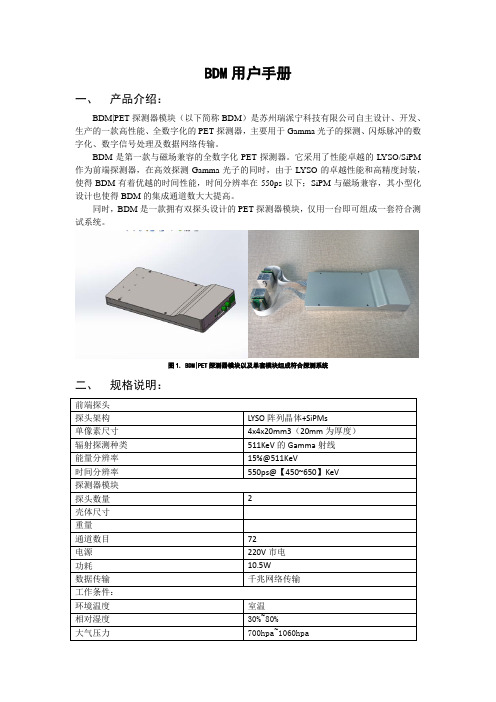
首先保证前端探头连接正常,沿图 2(左上)中箭头所示方向按压,保证探头连接器紧 密咬合。同时,参照图 2(右上)的方式,将 FFC 线接入 FFC 连接器,注意 FFC 线的插入方 向需与图中保持一致,将两个探头以图 2(下)的方式与探测器主体模块连接。
图 2. 左上:前端探头的连接器咬合;右上:前端探头的 FFC 线连接;下:双探头与模块的整体连接
按照图2下的连接方式与视角方向探头与探头2的通道对应情况如下图所示例如上面计算出的chnum如果等于10则该事件的发生位置对应下图的方向是探通道对应关系需要注意如果前端探头与bdm模块的ffc线连接顺序若与图2下的不同则通道与位置的对应情况也将发生变化
BDM 用户手册
一、 产品介绍:
BDM|PET 探测器模块(以下简称 BDM)是苏州瑞派宁科技有限公司自主设计、开发、 生产的一款高性能、全数字化的 PET 探测器,主要用于 Gamma 光子的探测、闪烁脉冲的数 字化、数字信号处理及数据网络传输。
BDM用户手册-瑞派宁
图 1. BDM|PET 探测器模块以及单套模块组成符合探测系统
二、 规格说明:
前端探头 探头架构 单像素尺寸 辐射探测种类 能量分辨率 时间分辨率 探测器模块 探头数量 壳体尺寸 重量 通道数目 电源 功耗 数据传输 工作条件: 环境温度 相对湿度 大气压力
如图 3 所示,BDM|PET 探测器模块有四个接口:Micro-USB、时钟接口、电源接口、网线接 口。在采集数据前,首先根据以上内容将探头与主体模块连接,然后使用时钟线连接探测器 和时钟模块,使用网线连接探测器和上位 PC,使用配置线连接探测器和上位 PC,最后通过
将 12V 适配器和 5V 适配器接入 220V 市电分别给探测器和时钟模块供电(两者不能混淆)。 在硬件连接正常及供电情况下,在上位机捕获传输的 UDP 数据包进行数据采集。 在正式采集存储数据前,建议使用时钟模块上的复位键对探测器进行复位。方法是在保证正 常硬件连接及供电情况下,按一下复位按键(按后复位按键处于下压状态),隔 1~2 秒后, 再按一下复位按键(此后复位按键处于弹起状态)。注意,当时钟模块的复位按键处于下压 状态时,探测器将不会发送数据至上位 PC。
四、 使用说明:
1. 数据采集:
首先保证前端探头连接正常,沿图 2(左上)中箭头所示方向按压,保证探头连接器紧 密咬合。同时,参照图 2(右上)的方式,将 FFC 线接入 FFC 连接器,注意 FFC 线的插入方 向需与图中保持一致,将两个探头以图 2(下)的方式与探测器主体模块连接。
图 2. 左上:前端探头的连接器咬合;右上:前端探头的 FFC 线连接;下:双探头与模块的整体连接
图 3. 单一事件数据说明
低压电动机 设定数据表北京北斗银河公司

BDM100系列微机电动机保护监控装置保护设定值参考北京北斗银河科技有限公司保护 名称 参数名称设定范围推荐 整定值备注通讯地址AD1 - 255 装置通信地址,视现场通讯要求设定1.00-5.00A电机额定电流二次值。
(In=5A ),定义见《BDM100装置使用说明书》 额定电流Im0.10-1.00A电机额定电流二次值。
(In=1A ),定义见《BDM100装置使用说明书》CT 变比Rt 1 - 500 与Im 配合使用来显示一次侧电流值,定义见《BDM100装置使用说明书》起动时间过长保护 允许起动时间Ts1 - 99S注1断相保护断相延时Td 0.1 - 20.0S 2.0S 短时工作或断续工作的电动机或额定功率不超过3kW 的电动机,可不设置断相保护。
【2】零序倍数I0 0.1 – 9.0 零序过流保护 零序延时T0 0.1 - 5.0S 注2 不平衡度△% 10% - 60% 15% 不平衡度整定 电流不平衡保护 不平衡延时T △ 1 - 120S 10S 不平衡保护延时堵转倍数Ir 2.0 - 8.0 2.5 堵转倍数(相对于Im 的倍数)堵转保护堵转延时Tr 1.0 - 25.5S 10S 堵转保护延时热过载延时TL1–40S5S电机在6倍额定电流下所允许的过载时间热过载保护过热复位延时Re0–30min10min过热跳闸后出口复位的延时,级差1min(对于增安型电机应设为手动复位,即00)防爆电机EExe 的热过载保护 反时限堵转延时tE 1.0–15.0S 注3再起动延时Tre 0.1 - 25.5S 最大允许再起延时 1.0 - 60.0S 自动重起动恢复电压值UH160~220V 低电压动作值UF 110~190V 低电压保护 低电压动作延时 1 – 25.5S 注4 过电压动作值 1.05-1.50Un 1.2 过电压整定值过电压 过电压动作延时 1 – 25.5S 10S欠电流动作值 0.2 - 0.95 0.6 欠电流倍数(相对于Im 的倍数)欠电流保护欠电流动作延时 1 - 60S 30S 欠电流保护延时保护投退0 - 8191定义见《BDM100装置使用说明书》注1:启动时间是指电动机在零转速的情况下,交流电动机在静止状态下从额定电压和额定频率的供电线路中获得启动电流开始计起,拖动额定负载,直到电机达到额定转速(或额定电流)时所需要的时间。
BDM100-M微机监控电机保护器的应用

0 . 引 言
4 . B DM1 0 0 一 M 的 数 据 显 示 及 实 际 应 用
4 . 1实时测量数据显示 当B D M1 0 0 一 M 通 电后进 人数 据循 环 显示 在 此状 态下 按 S HI F T 键, 定点 显示 当前屏 内容 ; 此后按 AD D键 , 按顺 序显示下一屏 内容 。 在 按 一次 S HI F T键 又 回 到循 环 显 示 状 态 4 . 2 B D M1 0 0 一 M 在 生 产 中的 节 能 应 用 为了确保生产 的平稳运行 . 石化总厂 的机 泵配备 为两 台( 一 台运 行, 一台备用) 。 在 以往的工作中 。 采用测量电流的方式 . 选择电流小的 泵作为主泵 , 根据多年的工作 实践 发现 , 由于运行环境和方式 的不 同 .
( 3 ) 交流采样 , 测量 A、 B、 c三相 电流 , 自动计算零 序电流 . 不需要 中石化销售公 司各下属单位有相 当数量 的电动机 在使 用 . 经常因 外加零序互感器 为电机过载 、 缺相 、 堵转 、 接地 、 三相电流不平衡等造成 电动 机的烧毁 . ( 4 ) 可取 代电流表 、 热继 电器 、 时间继 电器 、 零序保护继 电器及零 对模 拟量输入, 开关 量输入和输 出模件 . 其 内部具有 而传统 的电机保护效果不甚理想 ,致使电机经常 出现故 障甚 至烧毁 序 电流互 感器等, 随着新装置 的增加 . 电动机数量的增多 . 我公 司引进了 B D M1 0 0 一 M系 完善 的电气安全 隔离 列 微 机 监 控 电机 保 护 器 ( 5 ) 3 ~ 8路开关量输人, 带 当地 和远 方变位显示, 可显示 电机运行 、 保护动作等信号 1 . B D M1 0 0 一 M 保 护 器 和 传 统 电 动 机 保护 的 区 别 ( 6 ) 日历 时 间设 置 显示 我公司最早使用 的电动机过载 保护 、 断相保 护 、 短路保 护等都是 ( 7 ) 4个设置按键 , 可执行各种 功能的就地 操作 , 保护 功能可实现 分散型继 电器保护 , 所 用保护继 电器元 件分散 、 效果差 、 故 障率高 . 存 远方修改定值 , 报警信号可实现远方复归 。 在功能少 , 对 电机发 生扫膛 、 堵转 、 低电压等故 障不起作用 . 而且重复 远方 投切 , ( 8 ) 提供一个 电动机工艺联锁 要求 的开关 量输 入 . 硬 件和软件 的 性差 , 大电流过 载或 者短路故 障后不能重复使用 , 调 整误差大 、 易受环 以取得最大 的可靠性 境温度的影响误 动或者拒 动. 性能指标落后等缺 陷 当系统发生晃 电 连续 自我检测 , ( 9 ) 采用 R S 4 8 5 / MO D B U S R T U通信总线 , 可广泛应用 于各种监控 或者电压 降落 , 将影 响电机 的运行 , 甚至影响生产 . 这样 还要配备 电机 抗 晃 电 或 电 机再 启 动装 置 , 不 仅 增 加 了 电气 设 备 . 还 增 加 了维 修 量 所 系统作为电动机智 能化监控单元 以随着节能降耗 、 淘汰落后 电气设备 . 新 的电机综合保 护器应运而生 我公 司选 用 了 B D M1 0 0 一 M系列微机监控 电机保 护器 .它的故障率极 低, L C D液晶全 中文显示 , 可取代电流表 、 电压表, 电度表熟 继电器 、 时 间继 电器 、 零 序保护继 电器及零序 电流互感器等 . 具 有再启 动功能 、 接 地 故障保 护, 电量计量 和电机运转时 问统计等功能 . 技术先进 保护功 能齐全 , 参数设 置方便 , 跳 闸故 障代码全部是 中文显示 . 跳闸故障代码 示准确 , 维护人 员根据 跳闸故 障代码显示 , 能够 迅速 、 准确排 查故 障. 简单易学 , 大大提高 了工作 效率 所 以在我公 司新上 的成品油库 中 .所有电动机 的保护都 采用 了 B D M1 0 0 一 M系列微机监控 电机保护 器。
低压调试总结

低压调试总结送电前,对柜子进行全面除尘,取出柜子里遗留的杂物,关门上锁,测量绝缘合格才可以送电。
调试要有专人统一指挥,专人操作,不可随意乱动,以免发生危险。
接通临时电后,发现零线对地电压有12伏,导致部分指示灯虚亮,这是厂里老系统接地不好的缘故。
低压微机保护调试马保、线路保护定值密码1111BDF100-C+速断保护6倍额定电流速断延时0.1 s定时限过流一段2倍过流一段延时1s保护投退 5BDF100-M+速断保护6倍额定电流速断延时0s速断保护投退投入跳分闸2定时限过流一段2倍定时限过流一段延时5倍定时限过流一段保护跳分闸1反时限过流保护1反时限复位延时0反时限过流保护跳分闸1过电压保护设置1.2过电压延时10过电压保护投退跳分闸1低电压保护设置0.7低电压延时3低电压保护投退跳分闸1恢复电压值Uh 0.9BDM100-M+允许启动时间Ts<45KW 10>45KW 12启动时间过长保护投退投跳接触器断相延时Td 2断相保护投退投入跳接触反时限堵转延时Te(防爆电机) 4.6反时限堵转保护投入跳接触不平衡保护设置20%不平衡延时10不平衡保护投退投入跳接触器堵转保护3堵转延时5堵转保护投退投入跳接触器热过载保护设置1热过载复位延时0热过载保护投退投入跳接触器过电压保护设置 1.2过电压延时3过电压保护投退投入跳接触器瞬时再启动时间0.5BDM100-C+允许启动时间6s断相延时Td 2不平衡度20%堵转倍数lr 3堵转延时Tr 5热过载延时Tl 1过热复位延时Re 0反时限堵转延时(防爆电机)Te 4.6保护投退182调试中出现的问题:1、BDF 电流值要达到额定值的20%以上才显示电流2、外置CT较大,不能起到保护作用。
额定电流的设定范围是外置CT值的40%到100%,需更换小的外置CT.3、A11-6 BDM 100C+合闸状态S1 S2 指示灯都亮(S1断路器S2接触器)BDM100 c+ B4公共端B1 接QF 的NO 触点(S1)B2 接KM的NO 触点(S2)S1 S2 是QF KM 的状态指示,接的是QF KM 的辅助触点,注意开闭状态C7-1 QF KM RUN RX 灯均不亮,C11-2 合闸未启动状态QF 灯不亮B6-5吸合不启动无电流(出线电缆被人剪断)A26-2 A12-2 A12-4 A12-6 25-1,S1 S2指示灯亮不亮的问题:辅助触点接的不对,不行就更换新的马保4、马保端子和外置CT接线,外置CT上标有ABCN,再依信号电缆的颜色接到马保的相应端子上。
BDM100系列技术资料V2.1

5.1.2 防爆电机 EExe 热过载保护(tE 时间保护) ..............................................................................33 5.1.3 断相保护 ....................................................................................................................................34 5.1.4 三相电流不平衡保护 ..................................................................................................................35 5.1.5 堵转保护 ....................................................................................................................................35 5.1.6 起动时间过长保护......................................................................................................................36 5.1.7 零序过流保护 .............................................................................................................................37 5.1.8 自动重起动.................................................................................................................................37 5.1.9 欠电流保护.................................................................................................................................38 5.1.10 低电压保护.................................................................................................................................39 5.1.11 过压保护 ....................................................................................................................................39 5.1.12 漏电保护 ....................................................................................................................................40 5.1.13 工艺联锁分闸 .............................................................................................................................41 5.1.14 工艺联锁合闸 .............................................................................................................................41 5.1.15 速断保护 ....................................................................................................................................42 5.1.16 溢出分断 ....................................................................................................................................42
- 1、下载文档前请自行甄别文档内容的完整性,平台不提供额外的编辑、内容补充、找答案等附加服务。
- 2、"仅部分预览"的文档,不可在线预览部分如存在完整性等问题,可反馈申请退款(可完整预览的文档不适用该条件!)。
- 3、如文档侵犯您的权益,请联系客服反馈,我们会尽快为您处理(人工客服工作时间:9:00-18:30)。
北京北斗银河科技有限公司
地址:北京市昌平区科技园永安路26号邮编:102200
售后电话:0 0
传真:0
网址:使用说明书
产品型号:BDM100-M+
产品名称:低压电动机微机保护监控装置
北京北斗银河科技有限公司
版权所有·本公司保留解释、更改其内容的权利
161.装置功能表
1 2.技术数据
输入/输出
2
注:CT变比及额定电流输入方法:
设置CT变比Rt和额定电流Im(Im是电动机额定电流二次值),举
现有电动机一台,额定功率:37KW,额定电压:380VAC,理想状态
下,三相对称,功率因数COS=1时,额定电流为56A。
第一步:设置Im和Rt
1,电动机的额定电流,选用额定输入为80A的外置CT。
2,CT变比Rt设为80(CT额定输入电流值)。
3,额定电流Im设为70%A(计算公式:电动机额定电流值/CT额
定电流值)。
第二步:设定参数后,按RESET键,保存退出。
15
14
通讯
环境条件
3
3.安装说明
产品的机械尺寸如下图示,尺寸允许误差范围±0.1mm, 建议开孔尺寸(宽*高):*56.5mm(+0.5mm)
互感器安装
3.2.1电流穿线方式
电流穿线方向从带*标志一侧穿入,从对面穿出3.2.2外置互感器安装尺寸
4
附表:保护功能参数值及顺序表
序号参数名称整定范围BDM100-M+系列定值描述
1通讯地址AD 1 - 255装置通信地址
2额定电流In40﹪-100﹪设置电机的额定电流所占百分比
3CT变比Rt 1 - 900CT额定电流
4联锁控制设置保护投退投入、退出
5允许起动时间Ts 1 - 99S
用于起动时间过长保护(对于增安型
电动机的起动时间(Ts)设定值应不
大于倍电机t E时间)
6起动时间过长保护保护投退投入断路器、投入接触器、退出
7断相延时Td - 断相保护延时
8断相保护保护投退投入断路器、投入接触器、退出
9反时限堵转延时t E~
增安型电动机堵转倍时允许的堵转
时间
10反时限堵转保护保护投退投入断路器、投入接触器、退出
11零序保护设置–零序过流倍数
12零序延时零序保护延时
13
12 BDCTAD-00(1A~40A)安装尺寸示意图如下(尺寸容差:±0.1mm):
BDCTAD-00(80A~160A)安装尺寸示意图如下(尺寸容差:±0.1mm):
5
BDCTAD-00(300A~600A)安装尺寸示意图如下(尺寸容差:±0.1mm):
BDCTAD-01(1A~40A)安装尺寸示意图如下(尺寸容差:±0.1mm):
BDCTAD-01(80A~160A)安装尺寸示意图如下(尺寸容差:±0.1mm):
6
BDM100-M+接线端子示意图
C1C2C3C4C5C6C7C8C10C11C12C13
装置异常
分断路器动作信号分接触器
L/+N/-GND
B1
+-
4~20mA IN
COM
IN1
B2B3B4B5B6B7B8B9
IN2IN3IN4IN5IN6
A3A4
In
In
A
5
A
6
A
7
A
8
A
9
A
1
A
1
1
A14
485
A
A13
485
B
IL
UA UB UC
IC
IB
IA
正转合闸
C9C14C15
反转合闸
BDM100-M+端子定义
端子号描述备注
A3IL漏电流输入
A4
IN模拟量公共端
A5
A6IA A相电流输入
A7IB B相电流输入
A8IC C相电流输入
A9UA A相电压输入
A10UB B相电压输入
A11UC C相电压输入
11
循环显示状态下,按下“增加”持续3秒后进入起动记录查询界面。
起动记录查询时按“设置”键可逐个故障进行查看,共存放8次起动记录,按“复位”键返回循环显示。
起动记录数据中的电流一律为CT二次侧电流。
BDM100-M+系列以中文显示起动以及起动电流数值。
实例如下:
参数设定
循环显示状态下第一次按“设置”键显示要求输入四位密码,输入密码(密码默认值为1111)按“设置”键确认。
若输入不正确,则提示“密码错误”,并返回循环显示,若输入正确随即进入参数设置状态。
进入参数设置状态后,利用“左移”键移位、“增加”键累加,“设置”键确认后,进入下一参数设置,设置完毕后必须按“复位”键保存设置并退出, 返回循环显示。
注:参数设置值及顺序见附表
10
BDCTAD-01(300A~600A)安装尺寸示意图如下
(尺寸容差:±0.1mm):
BDCTL外置式漏电流互感器安装尺寸示意图如下
(其中40A以下的用Φ27的,80A及160A的用Φ60的,
300~600A的用Φ85的,尺寸容差:±0.1mm):
注:互感器信号输出电缆必须直接接到综保上,且屏蔽层电缆必须可靠接地
7 4.使用说明
操作说明
8
实时测量
值显示
在实时测量值循环显示状态下按“左移”键,定点显示
当前屏幕内容; 此后按“增加”键,按顺序
显示下一屏内容。
再按一
次“左移”键又进入循环显示实时测量值。
显示内容
如下:
记录查询
循环显示状态下,按下“左移”持续3秒后进入故障记录查询界面。
故障查询时按“设置”键可逐个故障进行查看,共存放8次故障原因;按“增加”键可以对应故障的详细数据;按“复位”键返回循环显示。
故障数据中的电流一律为CT 二次侧电流。
BDM100-M+系列以中文显示故障原因及故障数据。
实例如下:
9。