CANBUS协议-物理层及链路层详细分析
CAN协议规范解析

CAN协议规范解析CAN(Controller Area Network,控制器局域网)是一种高性能、实时性强、可靠性高的现场总线通信协议。
它最初是由德国Bosch公司为汽车电子系统开发的,现已广泛应用于汽车、工业自动化、电力系统等领域。
CAN协议规范完整,包括物理层、数据链路层、网络层和应用层。
1.物理层CAN协议的物理层使用两根信号线CAN_H和CAN_L构成差分传输线路。
CAN_H线接收高电平信号,CAN_L线接收低电平信号,通过这种方式实现数据的传递和接收。
这种差分传输方式具有抗干扰能力强、传输距离远等优点。
物理层还包括传输速率的定义,CAN协议支持多种传输速率,常用的有1 Mbps、500 kbps、250 kbps、125 kbps等。
选择不同的传输速率可以根据实际需求进行配置。
2.数据链路层数据链路层主要负责将上层应用发送的数据封装成CAN帧,并在总线上进行传输。
CAN帧由以下四个部分组成:起始位(SOF)、标识符(ID)、数据域(Data)和CRC校验码。
起始位用于同步接收方的时钟,标识符用于区分不同的数据帧,数据域用于传输应用数据,CRC校验码用于检测数据的传输错误。
CAN协议支持标准帧和扩展帧两种类型的数据帧,标识符的长度不同,标准帧为11位,扩展帧为29位。
扩展帧可以提供更多的ID范围,适用于大规模网络通信。
数据链路层还包括数据帧的发送和接收机制。
CAN协议采用一种优先级机制,不同的数据帧有不同的优先级,优先级高的数据帧可以打断正在传输的低优先级数据帧。
这种机制能够保证高优先级数据的实时性和可靠性。
3.网络层网络层主要负责CAN网络中节点之间的通信,包括数据的路由和过滤。
CAN网络支持多个节点的连接,节点之间可以通过总线进行双向通信。
每个节点可以发送和接收数据帧,通过标识符来区分不同节点的数据帧。
网络层还包括数据的过滤和控制,可以根据接收节点的ID进行过滤,只接收符合条件的数据帧。
CAN的工作原理
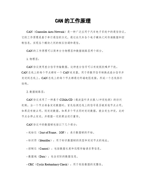
CAN的工作原理CAN(Controller Area Network)是一种广泛应用于汽车电子系统中的通信协议。
它的工作原理是基于串行通信的方式,通过在汽车各个电子模块之间传递数据和控制信息,实现各个模块之间的相互协调和通信。
CAN的工作原理可以简单分为物理层和数据链路层两个部分。
1. 物理层:CAN协议使用差分信号传输数据,这种差分信号可以有效抵抗噪声干扰。
CAN总线上的每个节点都有一个CAN收发器,用于将数字信号转换成差分信号并发送到总线上。
CAN总线上的每个节点都通过终端电阻连接,形成一个总线拓扑结构。
2. 数据链路层:CAN协议采用了一种基于CSMA/CD(载波监听多点接入/冲突检测)的访问机制。
当一个节点准备发送数据时,首先检测总线上的信号是否被其他节点占用,如果没有被占用,则发送数据。
如果多个节点同时发送数据,就会发生冲突,此时节点会停止发送,并根据一定的算法进行重传。
CAN协议中的数据帧包括以下几个部分:- 起始位(Start of Frame,SOF):表示数据帧的开始。
- 标识符(Identifier):用于标识数据帧的类型和发送节点的地址。
- 控制位(Control):包括数据长度和远程传输请求等信息。
- 数据域(Data):包含实际的数据信息。
- CRC(Cyclic Redundancy Check):用于校验数据的完整性。
- 确认位(Acknowledgement):用于确认数据的正确接收。
- 结束位(End of Frame,EOF):表示数据帧的结束。
CAN协议支持两种工作模式:标准帧和扩展帧。
标准帧使用11位的标识符,可以传输8字节的数据;而扩展帧使用29位的标识符,可以传输更大长度的数据。
CAN协议具有以下特点:- 高可靠性:CAN总线具有抗干扰能力强、误码率低的特点,能够在恶劣的环境下正常工作。
- 高实时性:CAN总线的通信速率较高,可以满足实时性要求。
- 灵活性:CAN总线可以连接多个节点,节点之间可以进行灵活的数据交换和控制。
can总线的原理
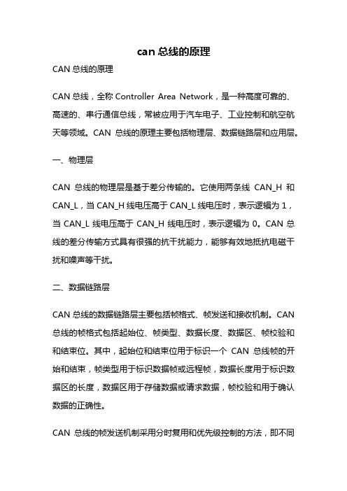
can总线的原理CAN总线的原理CAN总线,全称Controller Area Network,是一种高度可靠的、高速的、串行通信总线,常被应用于汽车电子、工业控制和航空航天等领域。
CAN总线的原理主要包括物理层、数据链路层和应用层。
一、物理层CAN总线的物理层是基于差分传输的。
它使用两条线CAN_H和CAN_L,当CAN_H线电压高于CAN_L线电压时,表示逻辑为1,当CAN_L线电压高于CAN_H线电压时,表示逻辑为0。
CAN总线的差分传输方式具有很强的抗干扰能力,能够有效地抵抗电磁干扰和噪声等干扰。
二、数据链路层CAN总线的数据链路层主要包括帧格式、帧发送和接收机制。
CAN 总线的帧格式包括起始位、帧类型、数据长度、数据区、帧校验和和结束位。
其中,起始位和结束位用于标识一个CAN总线帧的开始和结束,帧类型用于标识数据帧或远程帧,数据长度用于标识数据区的长度,数据区用于存储数据或请求数据,帧校验和用于确认数据的正确性。
CAN总线的帧发送机制采用分时复用和优先级控制的方法,即不同节点通过CAN总线共享相同的带宽,同时通过优先级控制来实现节点之间的数据传输。
当多个节点同时发送数据时,CAN总线会按照节点的优先级进行数据传输,优先级越高的节点先发送数据。
CAN总线的帧接收机制采用广播方式,即所有节点都能够接收到总线上的数据帧,并采用校验和来判断数据的正确性。
如果数据校验和正确,则可以接收数据,否则舍弃数据。
三、应用层CAN总线的应用层是通过标准的数据格式和协议来实现节点之间的数据交换。
CAN总线的应用层支持多种数据类型,包括数字、模拟和状态等,并支持多种通信协议,如CANopen、J1939和DeviceNet等。
CAN总线的原理是基于差分传输的物理层、帧格式、帧发送和接收机制以及应用层协议。
它具有高度可靠的性能、高速的传输速率和良好的抗干扰能力,广泛应用于汽车电子、工业控制和航空航天等领域。
CAN总线简易入门教程
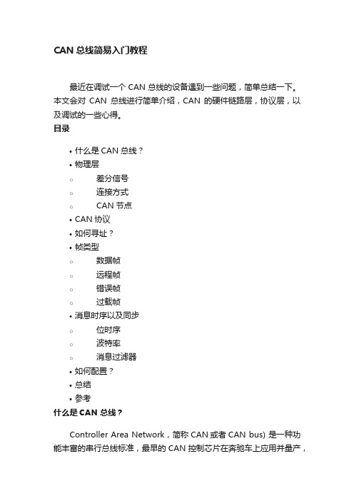
CAN总线简易入门教程最近在调试一个CAN总线的设备遇到一些问题,简单总结一下。
本文会对CAN总线进行简单介绍,CAN的硬件链路层,协议层,以及调试的一些心得。
目录•什么是CAN总线?•物理层o差分信号o连接方式o CAN节点•CAN协议•如何寻址?•帧类型o数据帧o远程帧o错误帧o过载帧•消息时序以及同步o位时序o波特率o消息过滤器•如何配置?•总结•参考什么是CAN总线?Controller Area Network,简称CAN或者CAN bus) 是一种功能丰富的串行总线标准,最早的CAN控制芯片在奔驰车上应用并量产,因为支持多主机,多从机的优点,所以一辆车所有控制器,传感器,电子设备直接的通信只需要两条线就够了,大大优化了整车的布线。
[^wiki can bus]随着技术的不断发展,CAN发布了相应的标准,国际化标准组织,公布了CAN的不同标准;标准涵盖内容ISO 11898-1 数据链路层ISO 11898-2 高速CAN的物理层ISO 11898-3 低速容错CAN的物理层ISO 11898-1 ,ISO 11898-2是对应的设计标准,去搜索就可以知道这个技术点是如何进行设计的。
物理层差分信号这里我们介绍一下物理层,什么是物理层呢?就是CAN的电信号的传输过程。
CAN是串行异步通讯,只有CAN_HIGH和CAN_LOW 两条差分信号线,数据通过差分信号的方式进行通讯,其优点就是可以增加信号的抗干扰能力,抑制共模信号的干扰;具体如下图所示;所以,信号在变成一个字节一个字节的数字信号之前,就是按照这种差分形式的模拟信号来传输的。
我们可以简单地理解一下,当CAN_HIGH减去CAN_LOW大于某个阈值的时候,可以把它当做逻辑高,反之,当小于某一个阈值时,就变成逻辑低。
下面我们再来看看CAN总线设备之间是如何连接的。
连接方式CAN总线支持多个节点挂载在总线上,比较类似I2C总线,可以在SCL和SDA上挂载多个从机,具体如下图所示;不过CAN总线其实没有主从的概念,每个设备都是一个节点(Node),节点直接可以相互通讯,相较于I2C总线,CAN总线设置了终端电阻,常见的一种闭环连接模式,相对的还有开环的连接模式。
canbus标准
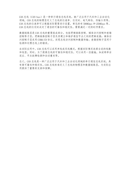
CAN总线(CAN-bus)是一种串行通信总线系统,被广泛应用于汽车和工业自动化领域,CAN总线的物理层定义了总线的位速率、位定时、电气特性、传输介质等。
CAN总线的位速率可以根据实际需要进行设置,常见的有500Kbps和250Kbps等。
CAN总线的位定时决定了通信的可靠性和稳定性,需要满足一定的时序要求。
数据链路层是CAN总线的重要组成部分,包括逻辑链路控制、媒体访问控制和差错控制等子层。
逻辑链路控制子层负责建立和维护通信节点之间的逻辑连接;媒体访问控制子层采用CSMA/CD协议,实现总线访问控制和数据传输;差错控制子层用于检测和处理总线上的错误。
在实际应用中,CAN总线可以采用单线或双线模式,根据实际情况选择合适的线数和线型。
同时,为了提高总线的可靠性和稳定性,可以采用一些措施,如波特率自适应、节点故障检测和自动重发等。
总之,CAN总线是一种广泛应用于汽车和工业自动化领域的串行通信总线系统,具有高可靠性和稳定性。
CAN总线标准定义了总线的物理层和数据链路层,为实际应用提供了重要的支持和保障。
(汽车诊断协议KWP2000,CANBUS)sid,pid应用详细分析

详细介绍-Upload/Download Functiona点l U击n添it加标题
35- RequestUpload(请求上传)
详细介绍-Upload/Download Functiona点l U击n添it加标题
36- TransferData(数据传输)
详细介绍-Upload/Download Functiona点l U击n添it加标题
详细介绍-Input/Output Control Functio点n击al添加标题
2F- inputOutputControlByCommonIdentifier Request SId (动作测试)
详细介绍-Remote Activation Of Routin点e 击Fu添nc加ti标on题al Unit
1A- readEcuIdentification Request Service Id(读ECU版本信息) 常用在KWP2000协议中 如: Req:82 10 F1 1A 94 31 Ans:8C F1 10 5A 94 50 5F 38 32 38 20 56 34 36 20 CC
详细介绍-Data Transmission Functiona点l U击n添it加标题
37- RequestTransferExit(传输结束)
第四部分
实例分析
实例分析
14蒙迪欧大灯协议文档
点击添加标题
实例分析
14蒙迪欧大灯协议文档
点击添加标题
实例分析
14蒙迪欧大灯协议文档点击来自加标题第五部分常见SID,PID组合
常见SID,PID组合
读VIN码(车架号) 0902 22F190
17- ReadStatusOfDiagnosticTroubleCodes service (读取诊断故障代码及状态)
can总线应用层协议实例解析
can总线应用层协议实例解析一、简介CAN总线(Controller Area Network)是一种广泛应用于汽车、工业自动化、家庭等领域的现场总线技术。
它是一种串行通信协议,可以在短距离和长距离传输中实现高可靠性的数据传输。
本篇文章将通过一个简单的CAN总线应用层协议实例来解析CAN总线的物理层、数据链路层和应用层。
二、物理层CAN总线的物理层包括传输介质、收发器和信号电平。
其中,传输介质可以是双绞线、同轴电缆等;收发器负责将数字信号转换为模拟信号或反向转换;信号电平采用差分电压进行数据传输,具有抗干扰能力强、传输距离远等优点。
三、数据链路层CAN总线的数据链路层定义了数据传输的规则和机制,包括数据帧、远程帧和错误控制。
数据帧由标识符、数据段和控制段组成,用于传输实际的数据;远程帧用于请求发送数据,但没有数据段;错误控制包括位错误检测和错误帧发送等功能。
四、应用层CAN总线的应用层定义了实际应用中需要的数据格式和协议。
例如,在汽车中,应用层可以定义车辆控制指令、传感器数据等的数据格式和协议。
应用层还提供了应用程序接口,使得用户可以轻松地使用CAN总线进行通信。
五、协议实例下面是一个简单的CAN总线应用层协议实例,用于控制车辆的灯光系统:1. 数据帧格式:每个数据帧包括标识符、控制段和数据段。
在此实例中,标识符表示灯光控制指令,控制段包括指令类型和指令参数,数据段包括指令的具体参数值。
2. 指令类型:指令类型包括打开前大灯、关闭前大灯、打开尾灯等。
每个指令类型都有一个唯一的标识符。
3. 指令参数:指令参数根据指令类型的不同而变化。
例如,打开前大灯的指令参数包括亮度等级和闪烁频率,关闭尾灯的指令参数为空。
4. 数据传输:当车辆的灯光控制系统接收到一个数据帧时,它会根据标识符判断指令类型和参数,然后执行相应的控制操作。
同时,控制系统还可以将传感器数据或其他信息封装成数据帧发送到CAN总线上。
5. 错误控制:如果数据传输过程中出现错误,控制系统会自动发送错误帧,通知其他节点出现错误。
CAN总线物理层
CAN Physical LayerThe Controller Area Network (CAN) protocol defines the data link layer and part of the physical layer in the OSI model, which consists of seven layers. The International Standards Organization (ISO) defined a standard, which incorporates the CAN specifications as well as a part of physical layer: the physical signaling, which comprises bit encoding and decoding (Non Return to Zero, NRZ) as well as bit-timing and synchronization.Bit encodingNRZ compared with Manchester bit representationIn the chosen Non Return to Zero (NRZ) bit coding the signal level remains constant over the bit time and thus just one time slot is required for the representation of a bit (other methods of bit encoding are e. g. Manchester or Pulse-width-modulation). The signal level can remain constant over a longer period of time; therefore measures must be taken to ensure that the maximum permissible interval between two signal edges is not exceeded. This is important for synchronization purposes. Bit stuffing is applied by inserting a complementary bit after five bits of equal value. Of course the receiver has to un-stuff the stuff-bits so that the original data content is processed.Bit-timing and synchronizationNominal bit-timeOn the bit-level (OSI layer 1, physical layer) CAN uses synchronous bit transmission. This enhances the transmitting capacity but also means that a sophisticated method of bit synchronization is required. While bit synchronization in a character-oriented transmission (asynchronous) is performed upon the reception of the start bit available with each character, a synchronous transmission protocol there is just one start bit available at the beginning of a frame. To enable the receiver to correctly read the messages, continuous resynchronization is required. Phase buffer segments are therefore inserted before and after the nominal sample point within a bit interval.The CAN protocol regulates bus access by bit-wise arbitration. The signal propagation from sender to receiver and back to the sender must be completed within one bit-time. For synchronization purposes a further time segment, the propagation delay segment, is needed in addition to the time reserved for synchronization, the phase buffer segments. The propagation delay segment takes into account the signal propagation on the bus as well as signal delays caused by transmitting and receiving nodes.Two types of synchronization are distinguished: hard synchronization at the start of a frame and resynchronization within a frame.•After a hard synchronization the bit time is restarted at the end of the sync segment. Therefore the edge, which caused the hard synchronization, lies within the sync segment of the restarted bit time.•Resynchronization shortens or lengthens the bit time so that the sample point is shifted according to the detected edgeThe device designer may program the bit-timing parameters in the CAN controller by means of the appropriate registers.Interdependency of data rate and bus lengthDepending on the size of the propagation delay segment the maximum possible bus length at a specific data rate (or the maximum possible data rate at a specific bus length) can be determined. The signal propagation is determined by the two nodes within the system that are farthest apart from each other. It is the time that it takes a signal to travel from one node to the one farthest apart (taking into account the delay caused by the transmitting and receiving node), synchronization and the signal from the second node to travel back to the first one. Only then can the first node decide whether its own signal level (recessive in this case) is the actual level on the bus or whether it has been replaced by the dominant level by another node. This fact is important for bus arbitration.Some modern transceivers support no low data rates. Therefore on acquisition of transceivers the maximal required network length must be considered.Physical mediaThis clause is most interesting for system designers.The basis for transmitting CAN messages and for competing for bus access is the ability to represent a dominant and a recessive bit value. This is possible for electrical and optical media so far. Also powerline and wireless transmission is possible.For electrical media the differential output bus voltages are defined in ISO 11898-2 and ISO 11898-3, in SAE J2411, and ISO 11992 (see below).With optical media the recessive level is represented by "dark" and the dominant level by "light".The physical media most commonly used to implement CAN networks is a differentially driven pair of wired with common return. For vehicle body electronics single wire bus lines are also used. Some efforts have been made to develop a solution for the transmission of CAN signals on the same line as the power supply.The parameters of the electrical medium become important when the bus length is increased. Signal propagation, the line resistance and wire cross sections are factors when dimensioning a network. In order to achieve the highest possible bit rate at a given length, a high signal speed is required. For long bus lines thevoltage drops over the length of the bus line. The wire cross section necessary is calculated by the permissible voltage drop of the signal level between the two nodes farthest apart in the system and the overall input resistance of all connected receivers. The permissible voltage drop must be such that the signal level can be reliably interpreted at any receiving node.The consideration of electromagnetic compatibility and choice of cables and connectors belongs also to the tasks of a system integrator.assumed line length 100 mSpecific signal propagation time (ns/m)Maximum bit rate (kbit/s)5.0805.5736.0676.5627.058Network topologyThis clause is most interesting for system designers.Electrical signals on the bus are reflected at the ends of the electrical line unless measures against that have been taken. For the node to read the bus level correctly it is important that signal reflections are avoided. This is done by terminating the bus line with a termination resistor at both ends of the bus and by avoiding unnecessarily long stubs lines of the bus. The highest possible product of transmission rate and bus length line is achieved by keeping as close as possible to a single line structure and by terminating both ends of the line. Specific recommendations for this can be found in the according standards (i.e. ISO 11898-2 and -3).It is possible to overcome the limitations of the basic line topology by using repeaters, bridges or gateways. A repeater transfers an electrical signal from one physical bus segment to another segment. The signal is only refreshed and the repeater can be regarded as a passive component comparable to a cable. The repeater divides a bus into two physically independent segments. This causes an additional signal propagation time. However, it is logically just one bus system.A bridge connects two logically separated networks on the data link layer (OSIlayer 2). This is so that the CAN identifiers are unique in each of the two bus systems. Bridges implement a storage function and can forward messages or parts thereof in an independent time-delayed transmission. Bridges differ from repeaters since they forward messages, which are not local, while repeaters forward all electrical signals including the CAN identifier.A gateway provides the connection of networks with different higher-layer protocols. It therefore performs the translation of protocol data between two communication systems. This translation takes place on the application layer (OSI layer 7).Bus accessThe connection between a CAN controller chip and a two-wire differential bus a variety of CAN transceiver chips according to different physical layer standards are available (see below ISO 11898-2 and -3, etc.).This interface basically consists of a transmitting amplifier and a receiving amplifier (transceiver = transmit and receive). Aside from the adaptation of the signal representation between chip and bus medium the transceiver has to meet a series of additional requirements. As a transmitter it provides sufficient driver output capacity and protects the on-controller-chip driver against overloading. It also reduces electromagnetic radiation. As a receiver the CAN transceiver provides a defined recessive signal level and protects the on-controller-chip input comparator against over-voltages on the bus lines. It also extends the common mode range of the input comparator in the CAN controller and provides sufficient input sensitivity. Furthermore it detects bus errors such as line breakage, short circuits, shorts to ground, etc. A further function of the transceiver can also be the galvanic isolation of a CAN node and the bus line.Physical layer standardsISO 11898-2 high speedISO 11898-2 is the most used physical layer standard for CAN networks. It describes the bus access unit (implemented as CAN high-speed transceiver) functions as well as some medium-dependent interface features.In this standard the data rate is defined up to 1 Mbit/s with a theoretically possible bus length of 40 m at 1 Mbit/s. The high-speed standard specifies a two-wire differential bus whereby the number of nodes is limited by the electrical busload. The characteristic line impedance is 120 Ohm, the common mode voltage ranges from -2 V on CAN_L to +7 V on CAN_H. The nominal specific propagation delay of the two-wire bus line is specified at 5 ns/m. All these figures are valid only for a 1 Mbit/s transfer rate and a maximum network length of 40 m.In order to achieve physical compatibility all nodes in the network must use the same or a similar bit-timing. For automotive applications the SAE published the SAE J2284 specification. For industrial and other non-automotive applications the system designer may use the CiA 102 recommendation. This specification defines the bit-timing for rates of 10 kbit/s to 1 Mbit/s. It also provides recommendations for bus lines and for connectors and pin assignment.ISO 11898-3 fault-tolerantAn alternative form of bus interfacing and arrangement of bus lines is specified in ISO 11898-3 (fault-tolerant CAN). This standard is mainly used for body electronics in the automotive industry. Since for this specification a short network was assumed, the problem of signal reflection is not as important as for long bus lines. This makes the use of an open bus line possible.This means low bus drivers can be used for networks with very low power consumption and the bus topology is no longer limited to a linear structure. It is possible to transmit data asymmetrically over just one bus line in case of an electrical failure of one of the bus lines.ISO 11898-3 defines data rates up to 125 kbit/s with the maximum bus length depending on the data rate used and the busload. Up to 32 nodes per network are specified. The common mode voltage ranges between -2 V and +7 V. The power supply is defined at 5 V.Transceiver chips, which support this standard, are available from several companies. The fault-tolerant transceivers support the complete error management including the detection of bus errors and automatic switching to asymmetrical signal transmission.SAE J2411 single wireThe single-wire standard SAE J2411 is also for CAN network applications with low requirements regarding bit rate and bus length. The communication takes place via just one bus line with a nominal data rate of 33,3 kbit/s (83,3 kbit/s in high-speed mode for diagnostics). The standard defines up to 32 nodes per network. The main application area of this standard is in comfort electronics networks in motor vehicles.An unshielded single wire is defined as the bus medium. A linear bus topology structure is not necessary. The standard includes selective node sleep capability, which allows regular communication to take place among several nodes while others are left in a sleep state. Transceivers for this standard are available, too.ISO 11992 point-to-pointAn additional approach to using CAN low-speed networks with fault-tolerant functionality is specified in the ISO 11992 standard. It defines a point-to-point connection for use in e.g. towing vehicles and their trailers. For one vehicle with one trailer, a point-to-point connection is defined. For one vehicle with two trailers, a daisy-chain connection is defined. The nominal data rate is 125 kbit/s with a maximum bus line length of 40 m. The standard defines the bus error management and the supply voltage (12 V or 24 V). An unshielded twisted pair of wires is defined as the bus medium.OthersNot standardized are fiber-optical transmissions of CAN signals. Due to the directed coupling into the optical media, the transmitting and receiving lines must be provided separately. Also, each receiving line must be externally coupled with each transmitting line in order to ensure bit monitoring. A star coupler can implement this. The use of a passive star coupler is possible with a small number of nodes, thus this kind of network is limited in size. The extension of a CAN network with optical media is limited by the light power, the power attenuation along the line and the star coupler rather than the signal propagation as in electrical lines.Advantages of optical media are emission- and immission-free transmission andcomplete galvanic decoupling. The electrically neutral behavior is important for applications in explosive or electromagnetically disturbed environments.CAN总线物理层控制局域网(CAN)协议决定数据链路层和在OSI模式中部分物理层。
can的物理层标准
can的物理层标准
CAN(Controller Area Network)是一种用于控制系统中的实
时通信协议,它的物理层标准主要包括以下几个方面:
1. 传输介质:CAN协议可以使用不同的传输介质,包括双绞线、光纤和无线传输等。
2. 线缆类型:在CAN网络中,常用的线缆类型有两种,分别
为CAN高速线缆(CAN-High Speed)和CAN低速线缆
(CAN-Low Speed)。
3. 线缆结构:CAN线缆采用双绞线结构,即两根平行排列的
导线,其中一根为CAN高线(CAN-H)用于传输高电平信号,另一根为CAN低线(CAN-L)用于传输低电平信号。
4. 传输速率:CAN网络支持不同的传输速率,包括100 kbit/s、250 kbit/s、500 kbit/s和1 Mbit/s等。
5. 总线电压:CAN标准规定了CAN-H和CAN-L线上的电压
范围,通常为0V到5V之间。
6. 物理连接:CAN系统中每个节点的物理连接通常采用DB9
连接器或者M12连接器。
需要注意的是,CAN协议的物理层标准可能会根据不同的应
用场景和具体实现有所差异,上述只是一般情况下的标准。
can电路标准设计
can电路标准设计CAN电路标准设计是一种常用的通信协议,广泛应用于汽车和工业领域的电子系统中。
它的设计目的是在一根双向传输线上实现高速、可靠的通信,并且能够适应恶劣的环境条件。
在CAN电路标准设计中,主要包括物理层和数据链路层两个方面。
物理层是指电缆、电阻和收发器等硬件组成部分,用于传输和接收数据。
数据链路层则负责传输数据、错误检测和纠错等功能。
下面将分别介绍这两个方面的具体要求和设计原则。
首先是物理层的设计要求。
在CAN电路标准设计中,传输线一般采用双绞线或者双绞屏蔽线,以减少外界干扰。
电缆的长度、传输速率以及线路负载要根据具体应用场景进行选择和设计。
同时,还需要在电路中加入终端电阻,以保证信号质量和匹配阻抗。
收发器的选择也是关键,需要具备高速、低功耗、抗干扰等特性。
其次是数据链路层的设计要求。
CAN电路标准设计采用了CSMA/CD(载波监听多点接入/冲突检测)的共享总线机制。
在数据传输过程中,需要实现数据帧的发送、接收和错误检测等功能。
数据帧的格式包括起始位、帧ID、控制位、数据域、CRC校验等字段,需要按照标准来进行组织和解析。
在进行CAN电路标准设计时,还需要考虑一些设计原则。
首先是可靠性和稳定性,要保证在噪声和干扰的环境中能够正常工作。
其次是实时性和响应速度,要能够满足实时控制和通信的需求。
此外,还需要考虑成本、功耗和尺寸等因素,以实现经济、高效和紧凑的设计。
综上所述,CAN电路标准设计是一种广泛应用的通信协议,其设计要求包括物理层和数据链路层。
在设计过程中,需要考虑可靠性、稳定性、实时性等因素,并且合理选择电缆、电阻和收发器等硬件组成部分。
保持良好的设计原则可以有效地满足相关应用的通信需求。
- 1、下载文档前请自行甄别文档内容的完整性,平台不提供额外的编辑、内容补充、找答案等附加服务。
- 2、"仅部分预览"的文档,不可在线预览部分如存在完整性等问题,可反馈申请退款(可完整预览的文档不适用该条件!)。
- 3、如文档侵犯您的权益,请联系客服反馈,我们会尽快为您处理(人工客服工作时间:9:00-18:30)。
谢谢!
字节2-5 为报文识别码(过滤ID的高29位) 字节6-13 为数据帧的实际数据,远程帧时无效
ISO 15765协议数据格式(一)
N_AI:地址信息部分 N_PCI:协议控制信息部分 N_Data:数据区
ISO 15765协议数据格式(二)
SF_DL:单帧数据域的字节长度,N_PCI的长度不包括在内 FF_DL:多包数据的数据域字节总长度 SN:多包数据的数据包编号 FS:流控制状态信息 BS:数据块大小(Block Size) STmin:多包数据传输的最小时间间隔
CAN的链路层描述
CAN2.0A标准帧格式 CAN2.0B扩展帧格式 ISO 15765协议数据格式 命令交互方式
CAN2.0A标准帧格式
7
6
5
4
3
2
1
0
字节1
FF
RTR
x
x
DLC 数据长度
字节2
报文识别码 ID.10-ID.3
字节3
ID.2-ID.0
x
x
x
x
x
字节4
数据1
字节5
数据2
字节6
数据3
Tools : 08H FCH00H 10H 09H 01H 02H 03H 04H 05H 06H ECU : 08H FDH00H 30H 00H 00H 00H 00H 00H 00H 00H Tools : 08H FCH00H 21H 07H 08H 09H 00H 00H 00H 00H ECU : 08H FDH00H 10H 0FH 59H 02H FFH 01H 80H 00H Tools : 08H FCH00H 30H 00H 00H 00H 00H 00H 00H 00H ECU : 08H FDH00H 21H FFH 01H 79H F1H E3H 01H 62H ECU : 08H FDH00H 22H F1H FFH 00H 00H 00H 00H 00H
中是指从字节4-字节11. 字节2-3 :为报文识别码(过滤ID的高11位) 字节4-11:为数据帧的实际数据,远程帧时无效。
CAN2.0B扩展帧格式
7
6
5
4
3
2
1
0
字节1
FF
RTR
x
x
DLC 数据长度
字节2
报文识别码
ID.28-ID.21
字节3
ID.20-ID.13
字节4
ID.12-ID.5
字节5
字节7
数据4
字节8
数据5
字节9
数据6
字节10
数据7
字节11
数据8
CAN2.0A标准帧为11个字节,包括信息和数据两部分,前3个字节为信息部分。 字节1 :第7位FF表示帧格式(在标准帧中FF=0,在扩展帧中FF=1);第6位RTR 表示帧的 类型(RTR=0表示为数据帧 RTR=1表示为远程帧);DLC 表示在数据帧时实际的数据长度,上图
CAN的物理层描述
可分为单线CAN协议和双线CAN协议。单线CAN协议目前主要出现 在GM和OPEL车系里面,1号脚通讯,波特率为33.3K。双线CAN协议常 见的波特率有500K(6/14)、 500K(3/8)、 250K(6/14)、125K(3/11)、 50K(1/9),括号内为通讯脚位。单、双线CAN协议的命令交互格式基 本一致。
CANBUS协议物理层 及链路层详细分析
2012-2-20
目的
本文档的目的是指导我们熟悉CANBUS通讯协议的物理层及链路层,便于我 们更好的开展有关CANBUS的相关工作。
培训内容
什么是CAN CAN的发展历程 CAN的主要特性 CAN如何工作 CAN的物理层描述 CAN的链路层描述
什么是CAN
在这种情况下的交互,将发1帧回多帧和发多帧回1帧结合就可 以了。需要注意的是,对于不同的ECU,有的时候会通过一条 流控制帧将所有数据一次收完,有时候则是采用一对一的方式。
命令交互方式(六)
流控制帧说明:
流控制帧的第4个字节一般为0x30,第5个字节表示Receiver允许 Sender连续发送的最大帧数,若需要发送的帧数超过该值时, 则需要Sender再次发送流控制帧(如果该字节为0,表示发送多 帧的帧数无限制),第6个字节表示发送多帧时各帧之间最小的 时间间隔。
CAN如何工作(二)
CAN 能够使用多种物理介质,例如双绞线、光纤等,最常用的就 是双绞线。信号使用差分电压传送,两条信号线被称为“CAN_H” 和 “CAN_L”, 静态时均是2.5V 左右,此时状态表示为逻辑1 ,也可 以叫做“隐性” 。用CAN_H 比CAN_L 高表示的逻辑0, 称为“显 性”,此时通常电压值为CAN_H =3.5V 和CAN_L = 1.5V 。
命令交互方式(一)
发一帧回一帧 发一帧回多帧 发多帧回一帧 发多帧回多帧 流控制帧说明
命令交互方式(二)
发一帧回一帧:
Tools : 08H FCH 00H 03H 19H 02H FFH 00H 00H 00H 00H ECU : 08H FDH 00H 04H 59H 02H FFH 01H 80H 01H 00H
第一个字节的低4位表示除报文识别码的两个字节外其他字节 的长度,第四个字节03表示后面有效数据的长度。
命令交互方式(三)
发一帧回多帧: Tools : 08H FCH ECU : 08H FDH Tools : 08H FCH ECU : 08H FDH ECU : 08H FDH ECU : 08H FDH … ECU : 08H FDH ECU : 08H FDH ECU : 08H FDH ECU : 08H FDH
CAN,全称为“Controller Area Network”, 即控制器局域 网,是国际上应用最广泛的现场总线之一。最初,CAN 被设计作为汽 车环境中的微控制器通讯,在车载各电子控制装置ECU 之间交换信 息,形成汽车电子控制网络。比如:发动机管理系统、变速箱控制器、 仪表装备、电子主干系统中,均嵌入CAN 控制装置。
CAN的主要特性
低成本 极高的总线利用率 很远的数据传输距离(长达10Km) 高速的数据传输速率(高达1Mbit/s) 可根据报文的ID决定接收或屏蔽该报文 可靠的错误处理和检错机制 发送的信息遭到破坏后,可自动重发 节点在错误严重的情况下具有自动退出总线的功能 报文不包含源地址或目标地址,仅用标志符来指示功能、优先级信息
ID.4Hale Waihona Puke ID.0xxx
字节6
数据1
字节7
数据2
字节8
数据3
字节9
数据4
字节10
数据5
字节11
数据6
字节12
数据7
字节13
数据8
字节1:为帧信息 第7位FF 表示帧格式(在标准帧中FF=0,在扩展帧中FF=1);第6位RTR 表示
帧的类型(RTR=0表示为数据帧 RTR=1表示为远程帧); DLC表示在数据帧时实际的数据长度, 上图中是 指字节6-字节13
00H 02H 21H 00H 00H 00H 00H 00H 00H 00H 10H 82H 61H 00H 4CH 46H 50H 48H 00H 30H 00H 00H 00H 00H 00H 00H 00H 00H 21H 34H 41H 42H 43H 35H 36H 39H 00H 22H 30H 31H 38H 34H 32H 33H FFH 00H 23H FFH FFH FFH 2AHFFH FFH FFH
CAN如何工作(一)
CAN 通讯协议主要描述设备之间的信息传递方式。CAN 层的定义 与开放系统互连模型OSI 一致。每一层与另一设备上相同的那一层通 讯,实际的通讯发生在每一设备上相邻的两层,而设备只通过模型物 理层的物理介质互连,CAN 的规范定义了模型的最下面两层:数据链 路层和物理层。物理层:规定通讯介质的物理特性(如电气特性和信 号交换的解释);数据链路层:规定了在介质上传输的数据位的排列 和组织(如数据校验和帧结构)。
发第一条请求帧的时候,如果请求帧第4个字节高四位为1,41H是对 01的肯定应答 则表示发多帧,发送的命令数据长度有第4,第5个字节一起 决定,在这里数据长度为16H,这时候ECU响应0x30的流控制帧, Tools继续发送请求帧,发送完后,ECU响应正确的命令回复。
命令交互方式(五)
发多帧回多帧:
00H 2FH FFH FFH FFH FFH FFH FFH FFH 00H 20H FFH FFH FFH FFH FFH FFH FFH 00H 21H FFH FFH FFH FFH FFH FFH FFH 00H 22H FFH E4H 81H FFH 30H 00H 00H
发出请求帧后,如果响应帧的第四个字节高四位为1,则表示回多 帧。响应帧有效数据长度为0x1082&0x0FFF=0x82????,表示有130个有效 数据。设备紧跟着发送流控制帧来接收下面的有效回复数据,这个
一个由CAN 总线构成的单一网络中,理论上可以挂接无数个节点。 实际应用中,节点数目受网络硬件的电气特性所限制。例如当使用 Philips P82C250 作为CAN 收发器时,同一网络中允许挂接110 个节 点。
一个典型的CAN应用于汽车控制的例子如下所示:
CAN的发展历程
CAN 最初出现在80 年代末的汽车工业中,由德国Bosch 公司最 先提出。当时由于消费者对于汽车功能的要求越来越多,而这些功能 的实现大多是基于电子操作的,这就使得电子装置之间的通讯越来越 复杂,同时意味着需要更多的连接信号线。提出CAN 总线的最初动机 就是为了解决现代汽车中庞大的电子控制装置之间的通讯,减少不断 增加的信号线。于是他们设计了一个单一的网络总线,所有的外围器 件可以被挂接在该总线上。1993 年,CAN 已成为国际标准 ISO11898(高速应用)和ISO11519 低速应用。由于CAN总线具有很高的 实时性能,因此,CAN已经在汽车工业、航空工业、工业控制、安全 防护等领域中得到了广泛应用。