FOX 10A热式气体质量流量计.
热式气体质量流量计使用说明书

目 录安全使用仪表 (1)序言 (3)技术参数 (3)安装与连接 (4)运行调试 (11)故障排除 (18)附录1.结构尺寸图 (19)附录2.满管式流量计数据 (20)附录4.部分气体物理参数 (21)※安全使用仪表※阅读完毕本手册后请妥善并与本仪表一起流动保管。
请将本手册交与终端用户技术部门保存。
本手册中安全主要事项的重要等级以 危险 注意 进行分类。
以下标识可能出现在使用的用户手册中:此图表示可能会造成危险的事项。
此图表示必须引起注意的事项此图表示禁止的事项感谢阁下选购由我公司自主研发生产热式气体质量流量计,热式气体质量流量计用户手册记录了如何正确、安全的使用本产品。
本品是气体流量测量的精密电子式仪表。
为了防止仪表的损坏和发挥最佳性能和稳定运行,请在安装、通电、调试、设置仪表前,请认真阅读本手册。
本手册适用流量控制工程师,专业工程技术人员,或我公司认可具备的相关资质人员。
如果忽视该提示警告而进行错误的操作,可能造成人身伤亡,或者重大安全事故。
危险爆炸环境应用时选用防爆型仪表 确认仪表铭牌上是否有防爆认证标识及温度组别标识,没有此标识的仪表不能用于爆炸的环境。
仪表防爆温度组别必须满足现场防爆和温度的环境要求 当在有防爆要求的场合应用时,要对本仪表的防爆温度组别进行确认,是否可以满足现场防爆、温度的要求。
爆炸环境禁止带电开盖操作 进行接线操作时,要先断开电源再进行操作。
需要改正参数设置时。
可以选择远程修改,本安红外手抄器修改,或者在安全的环境修改成功之 后再回现场环境。
以免化生爆炸。
仪表的防护等级要满足现在工况的要求 仪表防护等级是按照GB4208-93(相当于IEC529)中的相关要求进行检验和划分的。
现场要求的防护等级,应低于或者等于仪表的防护等级,一确保仪表的工作环境良好。
确认供电类型 用户可以选择两种供电方式为仪表供电,有交流220V和直流+24V(货应指注明)安装通电前必须确认供电类型是否与仪表匹配。
热式气体质量流量计-360百科
热式气体质量流量计-360百科热式气体质量流量计是利用热扩散和热分布的原理,利用气体带走热量的多少来计算流量。
其测量结果受温度、压力变化影响较小,量程比可达到30∶1,安装方式为插入式,基本没有压力损失,适用于测量介质组分比较稳定的干燥气体的流量。
1、工作原理:大流量:热扩散原理,利用气体带走多少热量决定流量;小流量:热分布原理;2、系统组成:简单无活动部件、常温一体化、高温分体式;3、适用测量介质:干燥气体,介质组分稳定;4、系统误差:±1% 质量流量精度;5、系统智能化:多项参数修改,智能化;6、检定:工厂标定数据储存在仪表里,可以现场检定仪表性能,结果可溯源;7、量程比:大量程比,保证精度的前提下30∶1;8、流量结果:质量流量,温度、压力变化影响小;9、温压补偿:不需要;10、安装:小口径:管道式;大口径:插入式;安装简单快捷:不需要保温\导压管路,前后;直管段:3D/5D;安装成本低:在管道360范围内任何角度都可以安装;11、维护:属于免维护型,如需维护,可以实现在线不停产插拔维护;12、工厂标定:密闭环路模拟实际工况标定每一台都要实际标定;13、响应时间:1s;14、压力损失:插入式基本没有压力损失;15、系统重复性:重复性较好;16、温度对测量系统精度的影响:在±25℃范围内,±0.04 %FS;在±25~50℃范围内,±0.06 %FS;17、压力对测量系统精度的影响:压力变化0.006895MPa,精度影响0.02% FS;18、系统造价:性价比非常高,小口径相对价格高,大口径比孔板产品还便宜。
FOX 热质型号10A安装使用手册-英文

MODEL 10AINSTALLATION AND INSTRUCTIONMANUAL100133 Rev. NTABLE OF CONTENTSPage SECTION 1, INTRODUCTION (1)1.1 Theory of Operation (1)1.2 Dimension Details (2)1.3 Remote Dimension Details (3)1.4 Specifications (4)SECTION 2, INSTALLATION (5)2.1 Installation (Insertion Style) (5)2.1.1 Mounting (5)2.1.2 Installation Depth (5)2.1.3 Sensor Orientation (5)2.1.4 Insertion -Flowmeter Placement (6)2.2 Installation (Flow Body Style) (6)2.2.1 Mounting (6)2.2.2 Sensor Orientation (6)SECTION 3, DISPLAY (7)3.1 Display, Scientific Notation (7)3.2 Menu Options (8)3.3 Display Mode (9)3.3.1 Default Display (9)3.3.2 Alternating Displays (9)SECTION 4, PROGRAMMING (10)4.1 Program Access (10)4.1.1 Cancel (10)4.2 Duct Area Setup (10)4.2.1 Insertion Style (10)4.2.2 Flowbody (Inline) Style (11)4.3 4-20mA Setup (11)4.3.1 20mA Set (11)4.3.2 4mA Set (12)4.4 Alarm Setup (13)4.4.1 Standard/Failsafe Mode (13)4.4.2 High Alarm Set (13)4.4.3 Low Alarm Set (14)4.5 Damping Setup (15)4.6 Total Reset (15)SECTION 5, WIRING (16)5.1 Wiring Installation (16)5.2 Power Input Wiring & Grounding (16)5.3 4-20mA Output Wiring (Isolated) (17)5.4 4-20mA Output Wiring (Non-Isolated) (17)5.5 Alarm Output Wiring (17)5.6 Remote Wiring Installation (18)5.6.1 Explosion-Proof Remote Enclosure (18)5.6.2 Nema 4X Remote Enclosure (19)TABLE OF CONTENTS continued...SECTION 6, PREVENTATIVE MAINTENANCE (21)6.1 Access to Electronics (21)6.2 Sensor Cleaning (21)6.3 Breakage or Damage of Probe (21)6.4 Calibration (22)6.5 Fuse Replacement (22)SECTION 7, TROUBLESHOOTING (23)7.1 Customer Service and Shipping Instructions (24)USER PROGRAM SETTINGSNOTICEThis publication must be read in its entirety before performing any operation. Failure to understand and follow these Instructions could result in serious personal injury and/or damage to the equipment. Should this equipment require repair or adjustment beyond the procedures given herein, contact the factory at:FOX THERMAL INSTRUMENTS, INC.505 MAYOCK RD., SUITE A4GILROY, CA 95020(408) 847-2090FAX: (408) 847-1806Email: sales@Though the information provided herein is believed to be accurate, be advised that the information contained herein is NOT a guarantee for satisfactory results. Specifically, this information is neither a warranty nor guarantee, expressed or implied, regarding performance; merchantability; fitness; or other matter with respect to the products; nor recommendation for the use of the product/process information in conflict with any patent. Please note that Fox Thermal Instruments, Inc. reserves the right to change and/or improve the product design and specifications without notice.SECTION 1 - INTRODUCTIONThe Model 10A is an advanced Thermal flowmeter. It is Microprocessor-Based and Field programmable. The Fox Power Pro Sensor is designed for high sensitive to changes in gas flow resulting in improved accurate, response time, and rangeability.1.1Theory of OperationThe Thermal Sensor, in the Model 10A, operates on the law that fluids absorb heat. Therefore,a heated sensor placed in a fluid stream transfers heat in proportion to the streams massvelocity.Using a Bridge circuit, one sensor detects the fluid temperature and a second sensor is maintained at a constant temperature above the fluid's temperature. This circuit maintains accurate flow measurement over large temperature and pressure differences.Mass flowThe Model 10A measures mass flow rate, an advantage over most flowmeters, which measure volume flow rate. Volume flow is incomplete because temperature and pressure are unknown and must be measured separately.For example, the mass of a volume of Gas depends on its temperature and pressure. As temperature and pressure changes the gas volume changes but not its mass. Therefore a devise measuring mass flow is independent of temperature and pressure. By defining a Standard as 70E F and 1 Atmosphere, 1 Standard cubic foot of gas equals the mass that is in 1 cubic foot of this gas at 70E F and 1 Atmosphere.The Model 10A provides Standard Cubic feet per minute readings with no additional temperature and pressure measurements required.Model 10ABody Dia.Dim."L"Dim."H"1/4-inch 7.90 (20.0)7.80 (19.8)1/2-inch 12.0 (30.5)7.90 (20.1)3/4-inch 12.0 (30.5)8.00 (20.3)1-inch 15.0 (38.1)8.20 (20.8)1.5-inch 12.0 (30.5)8.50 (21.6)2-inch 12.0 (30.5)10.0 (25.4)3-inch 18.0 (45.7)10.0 (25.4)4-inch 18.0 (45.7)11.5 (29.2)6-inch24.0 (61.0)11.5 (29.2)1.2Dimension DetailsNote: Dimensions in parenthesis are centimeters.FLOW BODY STYLE with NPT ConnectionsFLOW BODY STYLE with FLANGE ConnectionsINSERTION STYLELength "LL"in inches4.0(10.2) 6.0(15.2)9.0(22.9)12.0(30.5)18.0(45.7)24.0(61.0)30.0(76.2)36.0(91.4)1.3Remote Dimension DetailsModel 10A REMOTE EXPLOSION PROOF ENCLOSUREREMOTE NEMA 4X ENCLOSUREModel 10Ascfmnm 3/hr Size min max min max 0.25-inch 0-0.70-140-1.20-240.5-inch 0-2.10-420-3.40-710.75-inch 0-3.70-740-6.30-1261-inch 0-60-1200-100-2041.5 inch 0-150-2800-250-4762-inch 0-230-4700-390-8003-inch 0-500-10000-850-17004-inch 0-900-18000-1530-30606-inch0-2000-40000-3400-68001.4 SPECIFICATIONS PERFORMANCE SPECSAccuracy:+/- 0.75% of reading + 0.5% of full scale Calibration: NIST traceable Repeatability:+/- 0.2% of readingResponse Time:0.9 seconds (One time constant)OPERATING SPECSFlowRates:Insertion Flowmeter0 to 20,000 sfpm (0 to 100 nmps) In-line FlowmeterNote: Standard conditions of air at 70E F and one atmosphere. Consult factory for other gases.Gas Pressure:Insertion Flowmeter 300 psig (21 barg)In-Line FlowmeterNPT 300 psig (21 barg)150# Flange 230 psig (16 barg)Note: Pressure ratings stated for 100E F (38E C).Temperature:Sensor -40 to 250E F (-40 to 121E C)High Temp. Sensor 32 to 482E F (0 to 250E C) Enclosure -40 to 131E F (-40 to 55E C)Input Power:Explosion proof enclosure 24 VDC +/- 10%m 0.5 amp Remote Nema 4X enclosure115/230 VAC, +/- 10%, 50/60 hZ, 0.25 amp Output:4-20mA, isolatedAlarm relay; dry contact; 50 VAC, 30 VDC, 3 ampPHYSICAL SPECSDisplay Parameters: Flow scfm (nm 3/h) Total scf (nm3) Elapsed time (hrs)Alternates between readings Remote cabling:2 conductor, 18 AWG, 500 ft. maxExplosion Proof Enclosure:Cast aluminum; FM and CSA approvedfor Class 1, Divisions 1, Groups B, C, & D Temperature: T3C (160E C)FM approved Dust Ignition Proof for Class II/III Division 1, Groups E, F & G; indoor/outdoor NEMA Type 4.Remote NEMA 4X Enclosure:Fiberglass; Non-explosion proof; NEMA 4X Sensor Wetted Materials:316 Stainless Steel, Hastelloy C-276Insertion Flowmeter: Probe diameter 1/2-inchInstallation Coupling 3/4-inch NPTModel 10ASECTION 2 - INSTALLATIONWARNING! All installation procedures must be performed with the power OFF. 2.1 Installation (Insertion Style)2.1.1 Mounting - Insertion StyleThe Model 10A is mounted through a 3/4-inch hole and 3/4-inch female NPT half coupling provided in the customer'sduct. Installation procedures must be a combination of theend user's best engineering practices, in compliance withlocal codes, and the manufacturer's recommendations.The following, general precautions should be observed:a. Exercise care during handling and installation to avoiddamaging probe or probe enclosure.b. The enclosure cover must be left on before and afterinstallation.c. Do not mount the Model 10A in direct sunlight.2.1.2 Installation deptha. Install the compression fitting into the 3/4-inch femaleNPT half coupling.b. Install the end of the probe 1/2-inch past centerline of theduct and tighten the compression fitting nut.Caution: Once the compression fitting is locked onto theprobe, the probe can be removed or rotated, but the insertiondepth is locked in place.2.1.3 Sensor Orientation - Insertion Stylea. Install the shorter sensor probe upstream from the longer one.(View A-A)Note: In extreme low flow measurements (below 30 ft/min),convection heat from the longer probe can contact the shorterprobe (see View A-A). In these applications, choose a mountingthat prevents this from occurring. (ex. horizontal mounting)b. Install unit with sensor probes parallel to flow within ±10E.(Section B-B)Model 10A2.1.4 Insertion Flowmeter PlacementInstall the Model 10A Insertion style flowmeter so that it is far enough away from corners, obstructions, or changes in line sizes (ten diameters upstream and five diameters downstream) to ensure a consistent flow profile.2.2Installation (Flow Body Style)2.2.1 Mounting - Flow Body StyleThe Model 10A is welded, threaded or flanged to thecustomers duct. Care should be taken so the diameter ofthe mating duct has the same diameter as the Model 10Aflow body or errors in flow readings can occur.Installation procedures should be a combination of theend user's best engineering practices, in compliance withlocal codes, and the manufacturer's recommendations.The following, general precautions should be observed:a.Care must be exercised during handling andinstallation to avoid damaging probe or probeenclosure.b.The enclosure cover must be left on before and afterinstallation.c.Do not mount the Model 10A in direct sunlight.2.2.2 Sensor Orientation - Flow Body Style1.Install the flow body so that the arrow on the outside of theflow body is in the direction of flow. This will insure theshorter sensor is upstream from the longer one.Note:In extreme low flow measurements (below 30 ft/min),convection heat from the longer probe can contact theshorter probe (see View A-A). In these applications,choose a mounting that prevents this from occurring.(ex. horizontal mounting).Model 10ASECTION 3 - DISPLAY3.1Display: Scientific NotationThe Model 10A displays in Scientific Notation. Scientific Notation consists of 2 factors.The first factor is a number greater than or equal to one (1) and less than ten (10). The second factor is a power of ten (10). See illustrated examples below.Example 1:4 foot diameter duct:π/4 x (4FT)2 = 12.57 FT 212.57 = 1.257x101Shown as 1.257 +1 FT 2Example 2:2 inch diameter duct .π/4 x (2/12FT)2 = 0.02182 FT 20.02182 = 2.182x10⁻²Shown as 2.182 -2 FT 2Damping Set Low Alarm Setpoint High Alarm SetpointTotal Reset ProgramAccess 4mA Setpoint Duct Area Set 20mA SetpointDisplayAccess Flow RateTotal Elapsed TimeFlow Rate3.2Menu OptionsThe table below summarizes the Model 10A's default display, alternating displays, and seven program menus.PROGRAM MENUS (see Sections 4.1 through 4.6)ALTERNATING DISPLAYS (see Section 3.3.2)DEFAULT DISPLAY (see Section 3.3.1)3.3Display ModeThere are two display types available; Default andAlternating. The Default display is factoryconfigured. If the Alternating display is desired,the jumper to the right (bottom side of centerboard, see illustration) must be removed. (Cuttingthe jumper out is acceptable.)3.3.1 Default DisplayIn default mode, the Model 10A displays"FLOW" ( Standard Volumetric) continuously."FLOW" (Standard Volumetric flow) is expressed in "Ft3/MIN " (cubicfeet per minute).3.3.2 Alternating DisplayThree displays are available under Alternating Display; Flow Rate, Total Standard Volume (TOT), and Elapsed Time (ET). The Display Jumper must be removed to access these displays (as shown above). Each display will alternate at 5 second intervals."FLOW" (Standard Volumetric flow) is expressed in "Ft3/MIN " (cubicfeet per minute)."TOT" (Total Standard Volume) is expressed in "Ft3" (cubic feet). "ET" (Elapsed time) is expressed in "Hour"(hours).SECTION 4 - PROGRAMMING4.1Program AccessProgram access is accomplished by a hardware shunt. Toprogram, move the shunt to the "upper" position as shown to theright. The "PROG" light illuminates when in Program mode.Upon completion of programming, return the shunt to the"lower" position or remove it entirely to eliminate unauthorizedaccess.4.1.1 CancelUsing Cancel any time before revised data is ENTERED, exits the menu and restores the original data. Cancel is initiated by pressing the two center keys, simultaneously.4.2Duct Area Setup4.2.1 Insertion StyleThe standard volumetric flow rate is calculated by multiplying the sensor's velocity by the duct area (See Section 3.1 for examples). The area's value must be in units of Ft2.Locate the "AREA" menu by pressing "ENTER" until "AREA"illuminates as shown.Set the desired "AREA" value. The first digit will flash. Set the desiredvalue by pressing the "up" or "down" arrow. (Ex. "5" entered.)Move to the next digit by pressing the "right" arrow.The second digit will flash. Set to the desired value by pressing the "up" or"down" arrow. (Ex. "7" entered.)Note: Follow this process for all digits.Continued on the next page.4.2Duct Area Setup (Insertion Style Only) continued...Move to the exponent digits by pressing the "right" arrow.Set the desired value by pressing the "up" or "down" arrow. (Ex: "+ 2"entered.) Note: Once the complete value is entered, any portion can bechanged as outlined above.Press "ENTER" to record the desired value. "OK" will flash signifying the"AREA" value has been accepted. The unit will automatically proceed tothe next program setup.4.2.2 Flowbody StyleThe duct area setup for flowbody (also known as Inline) style units are configured at the factory. No other adjustments are necessary.4.34-20mA SetupThe 4-20mA output indicates any flow rate that the customer selects as long as the flow meter has been calibrated within that range.4.3.120mA setLocate the "20mA" program menu by pressing "ENTER" until"20mA" illuminates as shown.Set the desired "20mA" value. The first digit will flash. Set thedesired value by pressing the "up" or "down" arrow. (Ex. "5"entered.)Move to the next digit by pressing the "right" arrow.Continued on the next page.4.3.120mA set continued...The second digit will flash. Set the desired value by pressing the"up" or "down" arrow. (Ex. "7" entered.)Note:Follow this process for all digits.Move to the exponent digits by pressing the "right" arrow.Set the desired value by pressing the "up" or "down" arrow. (Ex. "+2" entered.)Note:Once the complete value is entered, any portion can bechanged as outlined above.Press "ENTER" to record the desired value. "OK" will flashsignifying the "20mA" value has been accepted and the unit willautomatically proceed to the "4mA" setup.4.3.24mA SetSet the "4mA" value by following the same procedure as the "20mA" outlined in Section 4.3.1.4.4Alarm setupAn alarm condition occurs when a programmed value is exceeded. The HIGH and LOW alarms are programmed independently. This allows an alarm on the HIGH setpoint, LOW setpoint, or both.4.4.1Standard/Failsafe modeThe standard alarm mode energizesthe relay during an alarm condition.In Failsafe mode, the relay isenergized upon power up and de-energizes during an alarm condition orpower failure. If Failsafe mode isdesired, the jumper to the left (bottomside of center board, see illustration)must be removed. (Cutting the jumperout is acceptable.)4.4.2High alarm setLocate the "HIGH" program menu by pressing "ENTER" until"HIGH" illuminates as shown.Note: The alarm can be disabled by setting the value to 0.000 + 0.Set the desired "HIGH" alarm value. The first digit will flash. Setthe desired value by pressing the "up" or "down" arrow. (Ex. "5"entered.)CONTINUED ON THE FOLLOWING PAGE......Move to the next digit by pressing the "right" arrow.The second digit will flash. Set the desired value by pressing the"up" or "down" arrow. (Ex. "7" entered.)Note:Follow this process for all digits.Move to the exponent digits by pressing the "right" arrow.Set the desired value by pressing the "up" or "down" arrow.(Ex. "+ 2" entered.)Note:Once the complete value is entered, any portion can be changed following the procedure outlined above.Press "ENTER" to record the desired value. "OK" will flashsignifying the "HIGH" alarm value has been accepted. The unit willautomatically proceed to the "LOW" setup.4.4.3Low alarm setSet the "LOW" alarm value by following same the procedure as outlined in 4.4.2.4.5Damping setup"Damping" is an output filter that is extremely useful when noisy flow environments cause the display and output to fluctuate, making the display difficult to read. (Output updates at 2000 times per second. Dampening range is 1-32,000.)For example: A Damping value of "5" takes the last 5 readings, computes the average, and sends it to the output. During each update, the oldest reading is thrown out, the last 5 readings are gathered, the average is computed, and sent to the output.Locate the "DAMP" (damping) program menu by pressing "ENTER" until"DAMP" illuminates as shown.Set the desired "DAMP" value. The right digit will flash. Set the desiredvalue by pressing the "up" or "down" arrow. (Ex. "5" entered.) Move tothe next digit by pressing the "right" arrow. Note:"0" was acceptable inthis example and did not need to be changed.Press "ENTER" to record the desired value. "OK" will flash signifying the"DAMP" value has been reset. The unit will automatically proceed to thenext program setup.4.6Total Reset"TOTAL" is a count of standard volumetric flow (standard cubic feet) over an elapsed time.Totaling halts when the system is in program mode. To begin a new total and elapsed time, the values must be "reset" to zero.Locate the "TOT" (Total) program menu by pressing "ENTER" until"TOT" and the first digit illuminates as shown.Press both the "up" and "down" arrow simultaneously to reset the totalvalue to "zero".Press "ENTER" to record the desired value. "OK" will flash signifying the"TOT" value has been reset. The unit will automatically proceed to the nextprogram setup. Note: Cycle through the Program Setup Menus to reach"TOT" again to verify the Total Volume has been reset to zero. "ET"(Elapsed time) is also reset to zero when "TOT" is reset.WIRINGWARNING! All installation procedures must be performed with the power OFF.All plumbing and electrical installations of flow meters must be a combination of the end user's best engineering practices, in compliance with local codes, and the manufacturer's recommendations.Wiring InstallationWiring is accomplished by removing the Circuit board"Assembly" as shown in the figure to the right.a.Place Allen wrench (7/64" shipped with flow meter)in both top panel holes and loosen the 2 cap screwscompletely. Carefully lift assembly out of enclosure.b.Bring customer supplied wires into enclosure throughconduit hole. Cut wires to 4" service loop length(use Stranded copper wire, no larger than 16 gauge).Caution: Wires must not become pinched between theassembly's heat sink and enclosure upon reinstallation.ing wiring diagrams in Section 5.2, 5.3 and 5.4,attach wires to terminal block.d.Before placing assembly back into enclosure checkthe position of the 4 holes located in the enclosurebottom. Rotate assembly to the desired view angle, which will allow the Cap screwsto be reinstalled into 2 of these holes.e.Install the assembly into enclosure. Using the Allen wrench, tighten both Capscrews into enclosure holes.Caution: The assembly must be installed into enclosure to prevent electronics from overheating causing shut down of the Model 10A.Power Input Wiring and Groundinga. Power required 24Vdc+/- 10% 1 amp.b. Enclosure must be properly grounded to protect electronics from static discharges.(Grounding lugs are provided on the outside of the enclosure.)5.34-20mA Output Wiring (Isolated)5.44-20mA Output Wiring (Non-Isolated)5.5Alarm Output Wiringa.Maximum load 3amp at 50 Vac or 30 Vdc.b.It is recommended that a RC Surge suppressor be installed across the load tominimize transient voltages and extend relay life.Model 10A5.6 Remote Wiring InstallationWARNING! All installation procedures must be performed with the power OFF.All plumbing and electrical installations of flow meters must be a combination of the end user's best engineering practices, in compliance with local codes, and the manufacturer's recommendations.Note: Both enclosures must be properly grounded to protect electronics from static discharges. (Grounding lugs are provided on the outside of the enclosures.)Wiring installation is performed in two (2) areas: 24 Vdc power input and flow signal interconnect (2 wire).5.6.1 Explosion-Proof Remote Enclosure24 Vdc InputTwo (2) 3/4 NPT female holes are provided in the Remote Electronics Enclosure. (Reference Section 1.3 for more information.) Place power wires through the most convienent hole for(8 pin) 24 Vdc Power-In terminal. Connect wires to the terminals as shown in the diagrambelow.2 Wire Flow Signal InterconnectConnect the flow signal through the remaining clearance hole. Install 16 gauge, two wire, twisted/shielded pair through the proper conduit. Connect to proper terminal locations as shown in illustration below.Model 10A 5.6 Remote Wiring Installation continued....5.6.2 Nema 4X Remote EnclosureModel 10ANOTESModel 10AFox Thermal Instruments Inc., 505 Mayock Road, A4, Gilroy, CA 95020 (408) 847-2090PAGE 21SECTION 6 - PREVENTATIVE MAINTENANCEWARNING! Before attempting any maintenance take the necessary safety precautions before removing probe from duct (ex., purge lines of toxic and/or explosive gas,depressurize line, etc.).WARNING! Turn input power OFF before removing or installing circuit board assembly from enclosure.6.1 Access to ElectronicsThe explosion proof enclosure contains the Circuit board"Assembly" (CBA) as shown in the figure to the right. To remove the CBA for fuse replacement or to remove a jumper, loosen the 2cap screws (7/64”Allen wrench), which holds the enclosure to the base of the flow meter. Carefully lift assembly out of enclosure. Keep in mind the enclosure is attached to the flow meter via the wires connecting the CBAs to the connector. There is enough service loop to allow access to all the internal components.Before placing assembly back into enclosure check the position of the 4 holes located in the enclosure bottom. Rotate assembly to thedesired view angle, which will allow the Cap screws to be reinstalled into 2 of these holes. Install the assembly into enclosure. Using the Allen wrench, tighten both Cap screws into enclosure holes.6.2 Sensor CleaningEven though the sensor is insensitive to small amounts of contamination, continued use in dirty environments will necessitate periodic cleaning. Remove the unit from duct, exposing the sensor elements. If they are visibly dirty, clean them with water or alcohol (ethanol) and an artist’s brush until they appear clean again. Even though the sensor elements are rugged and breakage resistant,avoid touching them with any solid object and use a light touch while cleaning them.6.3 Breakage or Damage of ProbeIf the sensor is broken or damaged, the probe and electronics must be returned to the factory. A new sensor will be installed and calibrated. Refer to Section 7, CUSTOMER SERVICE AND SHIPPING INSTRUCTIONS.Model 10A6.4 CalibrationTo insure the continuing high accuracy of your Model 10A Flow Meter, Fox Thermal Instruments Inc. provides a full NIST traceable calibration.6.5 Fuse Replacement (Standard and NFP versions)WARNING! Turn input power OFF before removing or installing circuit board assembly from enclosure and before removing or installing fuses. Use only recommended fuse replacements.Verify the fuse is bad with an Ohm Meter . (Tworeplacement fuses are provided with each unit.)To replace bad fuse:A. Remove circuit board assembly from enclosure perSection 6.1.B. Pull fuse out of fuse holder with tweezers. Replacewith new fuse. (Littlefuse part number R451.750 or Foxpart number 100045). The fuse rating is ¾ amp.C. Replace 6-32 screws and circuit board assembly perSection 6.1.PAGE 22 Fox Thermal Instruments Inc., 505 Mayock Road, A4, Gilroy, CA 95020 (408) 847-2090Model 10A SECTION 7 - TROUBLESHOOTINGCAUTION! The electronics, sensor and interconnect wires supplied by Fox are calibrated as a single precision mass flow meter.Interchanging sensors or sensor wiring will impair the accuracy of the flow meter.If you experience any problem with your Model 10A Flow Meter call Fox’s Customer Service Department, Technical Assistance, at (408) 847-2090.Problem Possible Cause ActionUnit will not power-up a) No power inputb) Bad fusec) Input power reversedd) Bad power supply a) Turn power onb) Replace fuse. See Section 6.4.c) Verify correct polarity: +24 to Terminal 3, DC ground to Terminal 2d) Verify 24Vdc output on power supplyVelocity Measurementseems lowa) Probe not oriented properlyb) Sensors dirty a) Orient probe per Section 2.1.3b) Clean sensor. (Refer to Section 6, Preventative Maintenance)Velocity measurement is erratic or fluctuating NOTE: Display updates at 2 time per second. Analog out updates at 2000 times per second a) Very turbulent flowb) Sensor dirtyc) Sensor brokend) Probe not mounted securelye) Malfunction in flow metera) Adjust dampening per Section 4.5b) Clean sensor (refer to Section 6.2, PreventativeMaintenance)c) Return flow meter to Fox for repair (refer toSection 7.1, Shipping Instructions)d) Probe must be mounted securely without vibratione) Return flow meter to Fox for repair (refer toSection 7.1, Shipping Instructions)Velocity measurement stuck at 0Remote units only.a) 2 wire flow signalinterconnect wired improperlyb) Bad fuse on FlowTransducera) Check flow signal interconntion per wiringdiagram in Section 5.6.2 and re-wireb) Replace fuse. See Section 6.5Total Volume readout has frozen at x.xxx+18 or x.xxx-18(Computer Problem)a) Total value has reached it’smaximum valueb) Area value set erroneouslyhighc) Dampening over 32,000a) Reset Total Volumeb) Reset Areac) Reset dampeningReading frozen at maximum or minimum value a) Dampening set to zerob) Area set to zeroc) Sensor not connected tocircuitryd) Sensor brokena) Reset dampeningb) Reset Areac) Measure bridge current by taking voltage dropaccross TP3 - TP4d) Return flow meter to Fox for repair.。
热式气体质量流量计-百度百科
热式气体质量流量计-百度百科一、概述嘉可仪表JK系列热式气体质量流量计是利用热传导原理测流量的仪表。
热式气体质量流量计采用恒温差法对气体质量流量进行准确测量。
具有体积小、数字化程度高、安装方便,测量准确等优点。
二、工作原理热式质量流量计由传感器和信号分析、处理与控制单元两部分构成。
传感器一部分测量温度,而另一部分用于加热。
前者监控实际过程温度值;后者维持一恒定温度值,使其总是高于实际过程温度且与该过程温度保持恒定的温度差。
气体的质量流量越大,冷却效应就越大,维持差分温度所需的能量也就越大。
因此,通过测量加热器的能量便可得出被测气体的质量流量。
三、热式气体质量流量计产品特点:1、真正的质量流量计,对气体流量测量无需温度和压力补偿,测量方便、准确。
可得到气体的质量流量或者标准体积流量。
2、宽量程比,可测量流速高至100Nm/s底至0.5Nm/s的气体,可以用于气体检漏。
3、抗震性能好使用寿命长。
传感器无活动部件和压力传感部件,不受震动对测量精度的影响。
4、安装维修简便。
在现场条件允许的情况下,可以实现不停产安装和维护。
(请参见安全注意事项)5、数字化设计。
整体数字化电路测量,测量准确、维修方便。
6、采用RS-485通讯,或HART通讯,可以实现工厂自动化、集成化。
四、适用范围1、压缩空气2、锅炉房或干燥机中的天然气3、酿酒厂中的二氧化碳气体4、污水处理厂中的沼气和曝气5、生成气体(如氩气、氮气、二氧化碳、氦气、氧气)6、气体泄露检测嘉可仪表生产的热式气体质量流量计可以测量氧气、氮气、二氧化碳、天然气、压缩空气、煤气、沼气等各种气体(乙炔除外),嘉可仪表JK系列热式气体质量流量计种类齐全,有管道式热式气体质量流量计、插入式热式气体质量流量计、高温型热式气体质量流量计、高压型热式气体质量流量计、一体式热式气体质量流量计、分体式热式气体质量流量计等。
FOX流量计中文版资料

MODEL 10A热式气体质量流量计安装及调试说明书上海德菲系统控制技术有限公司地址:上海市丽园路333弄4号103电话:021 – 63162634,63164704传真:021 – 63136211邮编:200011目录第一部分介绍1.1 操作原理 (4)1.2 尺寸及安装细节 (5)1.3 分体尺寸及安装细节 (6)第二部分安装2.1 安装(插入式) (7)2.1.1 安装 (7)2.1.2 安装深度 (7)2.1.3 传感器方向 (7)2.2 安装(带测量管式) (8)2.2.1 安装 (8)2.2.2传感器方向 (8)2.3 安装位置 (8)第三部分显示3.1 显示,科学记数法 (9)3.2 菜单选择 (10)3.3 显示方式 (11)3.3.1 错误显示 (11)3.3.2 供选择的显示 (11)第四部分编程4.1 编程步骤 (11)4.1.1 取消 (11)4.2 管道面积设置 (11)4.2.1 插入式 (11)4.2.2 带测量管式 (11)4.3 4-20mA 设置 (11)4.3.1 20mA 设置 (11)4.3.2 4mA 设置 (11)4.4 报警设置 (11)4.4.1 标准/故障安全方式 (11)4.4.2 高报警设置 (11)4.4.3 低报警设置 (11)4.5 阻尼设置 (12)4.6 总体积重新设置 (12)第五部分接线5.1 接线安装 (12)5.2 电源输入接线及接地 (12)5.3 4-20mA输出接线(独立输出) (13)5.4 4-20mA 输出接线(非独立输出) (13)5.5 报警输出接线 (13)5.6 分体式接线安装 (13)5.6.1 24Vdc 输入 (13)5.6.2 两线制流量信号连接 (13)第六部分维护6.1 拆卸电子单元 (14)6.2 传感器清洗 (14)6.3 探头的破损 (14)6.4 标定 (14)6.5(标准或NFP单元) (14)6.5.1替换保险丝(分体式单元) (14)第七部分故障 (15)7.1 客户服务及装运说明 (15)注意在进行操作之前请仔细阅读此说明书。
VF10热式气体质量流量计
RTD Heater
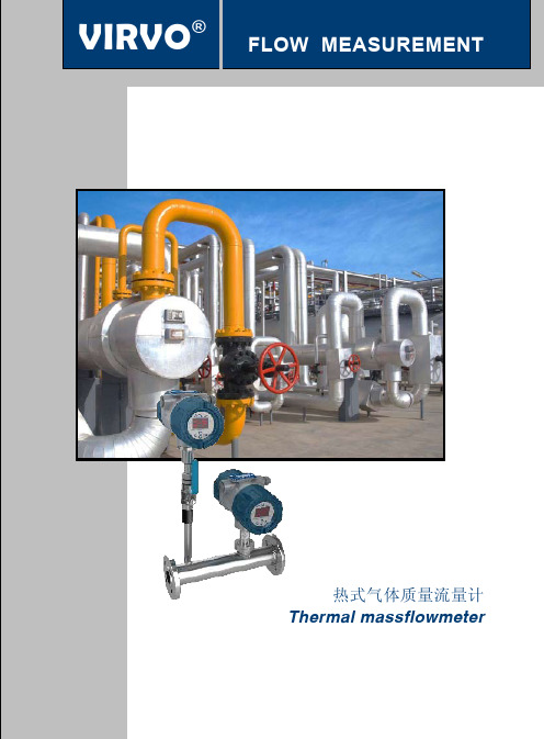
热式气体质量流量计是利用传热原理,即流动中的流体与热源之间的热量 交换关系来测量气体质量流量的仪表。 按气体对检测原件的热源的热量作用可分为热分布式效应和热耗散效应。 利用热耗散效应(金氏定律)的热式气体质量流量计作为一种测量气体质 量流量的直接式质量流量计以其压损低、流量范围大、高精度及高重复 性、无可动部件等显著优点在国内外众多行业工业过程控制中得到了长足 的发展和赢得了青睐。
13
PN40 (DIN)
S [mm]
重量 [kg]
4.5
0.3
108
135
17
7.0
0.7
123
150
17
8.5
1.0
158
185
17
13.0
2.3
187
220
22
17.0
4.1
注:当选用其他标准的法兰连接时,请咨询厂家索 取详细资料。
结构图
VI
114
RVO PROCESS CONTROL
VIRVO® Process Measurement and Control For Yours
IECEx 隔爆和防尘认证
证书编号 IECEx KEM 08.0001 Ga/Gb Ex d IIC T6 过程温度 (Tprocess) =85°C -30°C ≤环境温度 (Tamb) ≤+75°C IP66/67 Ga/Gb Ex d IIC T5 过程温度 (Tprocess) =100°C -30°C ≤环境温度(Tamb) ≤+80°C IP66/67 Ga/Gb Ex d IIC T4 过程温度 (Tprocess) =110°C -30°C ≤环境温度(Tamb) ≤+80°C IP66/67 Ex tD A21 IP66/67 T85 过程温度 (Tprocess) =85°C -30°C ≤环境温度(Tamb) ≤+75°C Ex tD A21 IP66/67 T100 过程温度 (Tprocess) =100°C -30°C ≤环境温度(Tamb) ≤+75°C Ex tD A21 IP66/67 T110 过程温度 (Tprocess) =110°C -30°C ≤环境温度(Tamb) ≤+75°C 注意:使用适于在温度比周围环境温度高 5°C 情况下工作的电源线
FOX流量计中文版

MODEL 10A热式气体质量流量计安装及调试说明书上海德菲系统控制技术有限公司地址:上海市丽园路333弄4号103电话:021 – 63162634,63164704传真:021 – 63136211邮编:200011目录第一部分介绍1.1 操作原理 (4)1.2 尺寸及安装细节 (5)1.3 分体尺寸及安装细节 (6)第二部分安装2.1 安装(插入式) (7)2.1.1 安装 (7)2.1.2 安装深度 (7)2.1.3 传感器方向 (7)2.2 安装(带测量管式) (8)2.2.1 安装 (8)2.2.2传感器方向 (8)2.3 安装位置 (8)第三部分显示3.1 显示,科学记数法 (9)3.2 菜单选择 (10)3.3 显示方式 (11)3.3.1 错误显示 (11)3.3.2 供选择的显示 (11)第四部分编程4.1 编程步骤 (11)4.1.1 取消 (11)4.2 管道面积设置 (11)4.2.1 插入式 (11)4.2.2 带测量管式 (11)4.3 4-20mA 设置 (11)4.3.1 20mA 设置 (11)4.3.2 4mA 设置 (11)4.4 报警设置 (11)4.4.1 标准/故障安全方式 (11)4.4.2 高报警设置 (11)4.4.3 低报警设置 (11)4.5 阻尼设置 (12)4.6 总体积重新设置 (12)第五部分接线5.1 接线安装 (12)5.2 电源输入接线及接地 (12)5.3 4-20mA输出接线(独立输出) (13)5.4 4-20mA 输出接线(非独立输出) (13)5.5 报警输出接线 (13)5.6 分体式接线安装 (13)5.6.1 24Vdc 输入 (13)5.6.2 两线制流量信号连接 (13)第六部分维护6.1 拆卸电子单元 (14)6.2 传感器清洗 (14)6.3 探头的破损 (14)6.4 标定 (14)6.5(标准或NFP单元) (14)6.5.1替换保险丝(分体式单元) (14)第七部分故障 (15)7.1 客户服务及装运说明 (15)注意在进行操作之前请仔细阅读此说明书。
fox

传感器 -40 to 120℃ 高温型: 120 to 350℃ 电子单元部分: -40 to 55℃
密封套安装耐压达 21 Bar,采用特殊结构可以有 更高耐压。
34
Fox 工业公司 Model 10A 热式气体质量流量计
15
操作原理-恒温差 (∆T)
电子单元感应 ∆T的减少 并且增加能量以维持恒温 差 ∆T 随着质量流量的减少, 电
子单元减少对加热探头的能 量供应。
传感器输 出信号
FOX流量计
对加热探头的总能量供应 正比于质量流量,微处理 器使输出信号线性。
流量率
16
与其它气体流量计比较
气体测量中,质量流量的测量通常需要参数, 与其它装置相比,热质量 流量计的优点- 简单.
37
热式气体质量流量计的一般应用
石油 化工 污水处理 环境工程 电厂 食品行业 一般过程处理
38
热式气体质量流量计的特殊应用
工厂压缩空气测量 天然气测量 锅炉的天然气和空气测量 污水处理瀑气测量 火炬气体测量 液化气和沼气测量 氢气测量 钢铁厂加气测量
39
热式质量流量计的特殊应用
灌装厂二氧化碳气体测量 供水厂杀菌氯气测量 蒸煮器气体测量 供水厂氧气或臭氧气体测量 食品长空气测量 窑炉二级进气控制 空气和氮气净化测量 尾气测量
压力每增加 10 psig 导致 8.7% 的误差 温度每增加 10℉(12℃)导致 1.8% 的误差
实际1 CF 的空气在 70 ℉ (21 ℃) & 1 atm 时= 1 scf(标准立方英尺) 实际1 CF 的空气 在70℉ (21 ℃) & 500 psi时 = 35 scf(标准立方英尺) 因此用体积流量计测量气体流量会带来重大误差
- 1、下载文档前请自行甄别文档内容的完整性,平台不提供额外的编辑、内容补充、找答案等附加服务。
- 2、"仅部分预览"的文档,不可在线预览部分如存在完整性等问题,可反馈申请退款(可完整预览的文档不适用该条件!)。
- 3、如文档侵犯您的权益,请联系客服反馈,我们会尽快为您处理(人工客服工作时间:9:00-18:30)。
MODEL 10A热式气体质量流量计安装及调试说明书北京德菲世纪仪表有限公司地址:北京市海淀区上地信息路1号1栋805电话:010 – 6296 2862传真:010 – 6296 2860邮编:100085网址:目录第一部分介绍1.1 操作原理 (4)1.2 尺寸及安装细节 (5)1.3 分体尺寸及安装细节 (6)第二部分安装2.1 安装(插入式) (7)2.1.1 安装 (7)2.1.2 安装深度 (7)2.1.3 传感器方向 (7)2.2 安装(带测量管式) (8)2.2.1 安装 (8)2.2.2传感器方向 (8)2.3 安装位置 (8)第三部分显示3.1 显示,科学记数法 (9)3.2 菜单选择 (10)3.3 显示方式 (11)3.3.1 错误显示 (11)3.3.2 供选择的显示 (11)第四部分编程4.1 编程步骤 (11)4.1.1 取消 (11)4.2 管道面积设置 (11)4.2.1 插入式 (11)4.2.2 带测量管式 (11)4.3 4-20mA 设置 (11)4.3.1 20mA 设置 (11)4.3.2 4mA 设置 (11)4.4 报警设置 (11)4.4.1 标准/故障安全方式 (11)4.4.2 高报警设置 (11)4.4.3 低报警设置 (11)4.5 阻尼设置 (12)4.6 总体积重新设置 (12)第五部分接线5.1 接线安装 (12)5.2 电源输入接线及接地 (12)5.3 4-20mA输出接线(独立输出) (13)5.4 4-20mA 输出接线(非独立输出) (13)5.5 报警输出接线 (13)5.6 分体式接线安装 (13)5.6.1 24Vdc 输入 (13)5.6.2 两线制流量信号连接 (13)第六部分维护6.1 拆卸电子单元 (14)6.2 传感器清洗 (14)6.3 探头的破损 (14)6.4 标定 (14)6.5(标准或NFP单元) (14)6.5.1替换保险丝(分体式单元) (14)第七部分故障 (15)7.1 客户服务及装运说明 (15)注意在进行操作之前请仔细阅读此说明书。
错误的理解将会导致人员伤害或仪器损坏。
维修及调试请与以下地址联系:FOX INDUSTRY505 MAYOCK RD., SUITE A4GILROY, CA 95020(408) 847-2090FAX: (408) 847-1806第一部分介绍Model 10A是一种智能、小巧、先进的热式流量计。
它的智能变送器与微处理器电子单元之间用坚固的铂金传感器连接,现场可编程。
它小巧的包装排除了传统的现场交叉连接,使Model 10A更容易安装。
Model 10A不仅带有传统的报警、4-20mA、累加器、显示和键盘功能,而且还具有创新的流量轮廓补偿、自检、安全通道和输出阻尼功能。
1.1 操作原理Model 10A的热式传感器是利用流体吸收热量的原理进行工作的。
因此,被加热的传感器调节的热量与流体的速度成比例。
Model 10A采用桥式环路,一个传感器测量流体温度,另一个传感器负责维持高于流体温度的恒温差。
这个环形电路可在高温和压差条件下进行精确测量。
质量流量Model 10A测量质量流量率,它优于一般的测量体积流量的流量计。
由于温度和压力是未知并且需要分别测量,因此体积流量是不完善的。
例如,一定体积的气体的质量决定于温度和压力,当温度和压力变化时气体的体积变化而质量不变。
因此,测量质量流量不需要温度和压力补偿。
在70华氏度、1个大气压条件下制订一个标准,即一标准立方英尺气体等于在70华氏度、1个大气压条件下一立方英尺气体的质量。
(在25℃、1个标准大气压条件下制订一个标准,一标方气体等于在25℃、1个标准大气压条件下一立方米气体的质量。
)Model 10A所提供的流量信息无需附加的温度和压力测量,读数为标准立方英尺每分钟。
(读数为标准立方米每小时。
)1.2 尺寸及安装细节Model10A 的尺寸是通过标签上的部件号来定义的。
MODEL 10A – XX - YYYXX :带测量管式为 XX A , 插入式为 XX B标签 XX标签XXB, 插入式标签YYY ,观测角度直径 尺寸 “A” 尺寸 “B” 最大流量 ft 3/min XX 1” 15” 8.5” 55 -1D 2” 12” 10” 220 -2D 3” 18” 10” 490 -3D 4” 18” 11.5” 870 -4D 6”24”11.5”1900-6D长度 “L” XX 6” -6 12” -12 18” -18 24” -24 30” -30 36”-36角度 YYY00 -000 900 -0901800 -180 2700 -2701.3 分体尺寸及安装细节Model10A 的尺寸是通过标签上的部件号来定义的。
XX :带测量管式=标签XX A ,或 插入式=标签 XX B标签XX B ,分体插入式XX “L”尺寸 -06 6” -12 12” -18 18” -24 24” -30 30” -3636”标签XX A , 分体带测量管式XX 直径 “A” 尺寸 “B” 尺寸 最大流量 SCFM-1D 1” 15” 8.5” 55 -2D 2” 12” 10” 220 -3D 3” 18” 10” 490 -4D 4” 18” 11.”5 870 -6D 6”24”11.5”1900第二部分安装注意!操作之前必须将电源关掉。
2.1 安装(插入式)注意:分体式单元不代显示。
2.1.1 安装---插入式Model10A通过用户管道上提供的3/4”NPT进行安装。
安装时要综合考虑现场条件以及生产厂家的建议。
安装时应注意以下几点:a挪动和安装时应避免损坏探头及外壳。
bc 请勿将Model10A安装于太阳直射的地方。
2.1.2安装深度a 将压紧装置装入用户的管道内(利用3/4NPT孔)。
b探头插入长度应超过管道中心1/2”。
注意:将压紧装置锁住后,探头可以移动或旋转,但插入长度已经被确定。
2.1.3传感器定向---插入式a 传感器中较短的探头应位于长探头的上游。
(图A-A)注意:在流速非常低的情况下(低于30英尺/分钟),来自长探头的对流热量将传递给短探头(图A-A),在这种条件下应选择其它安装方式。
(例如水平安装)b 传感器与流量方向平行度应小于±100。
(图B-B)2.2安装(带测量管式)注意:分体式单元不带显示。
2.2.1安装---带测量管式Model0A被焊接在用户的管道上。
应仔细将焊接端对接,以保证对接管道与测量管直径相同,否则将产生流量读数的误差。
安装时要综合考虑现场条件以及生产厂家的建议。
安装时应注意以下几点:a挪动和安装时应避免损坏探头及外壳。
bc 请勿将Model10A安装于太阳直射的地方。
2.2.2传感器定向---带测量管式1.安装测量管时应使管道外的箭头方向与流量方向一致。
以确保短探头位于长探头的上游。
注意:在流速非常低的情况下(低于30英尺/分钟),来自长探头的对流热量将传递给短探头(图A-A),在这种条件下应选择其它安装方式。
(例如水平安装)2.3安装位置Model10A的安装位置应远离弯头、阻碍物、变径等地方(上游10倍管径和下游5倍管径的直管段)以保证有规则的流体截面。
第三部分显示3.1显示:科学记数法Model10A以科学记数法显示。
科学记数法包含两个系数。
第一个系数大于等于1并小于10,第二个系数为10的幂,请参考下例。
例1:直径为4英尺管道:π/4 x (4FT)2 = 12.57 FT212.57 = 1.257 x 101显示 1.257+1FT2例2:直径为2英尺管道:π/4 x (2/12FT)2 = 0.02182 FT20.02182 = 2.182 x 10⁻²显示 2.182-2 FT23.2 菜单选项下表总结了Model10A的错误显示,3.3显示模式有两种显示模式;默认和交替显示。
默认显示是出厂设定状态,如果需要交替显示的话,右边的跳线必须被去掉。
(中间一层电路板的底部)。
3.3.1默认显示在默认模式下,将持续显示流量值。
流量的单位是M3/min(M3/hour)。
3.3.2交替显示在交替显示下三种显示将被交替;流量、累积流量和累计时间。
三种显示每5秒钟间隔显示。
流量的单位是M3/min(M3/hour),总流量的单位是M3,累计时间的单位是小时hour。
4.1调试过程进入编程由硬件实现。
将跳块移到“UPER“上。
编程模式下“PROG”灯亮。
编程结束后,将跳块放回原位“LOWER”或拆走,以免未授权者进入菜单。
4.1.1取消在修改的数值确认前用此键退出菜单,回复原来的数据。
同时按中间两个键初始化。
4.2截面积设定4.2.1插入式体积流量由测量到的流速乘以横截面积得到,横截面积必须以“FEET2”为单位。
按“ENTER”键直到“AREA”灯亮。
输入面积值时,用“RIGHT”键移动光标位置,用“UP”和“DOWN”键修改数值。
移动光标到指数位,用“UP”和“DOWN”选择“+/-”,并设定数值。
完成后,按ENTER键存储数值,并进入下一个参数设定。
4.2.2流体类型这部分由厂家组态,用户不必调整。
4.3 4- 20mA设定在标定范围内,4-20MA输出用户选择的任何流量。
4.3.1 20MA设定按ENTER 键直到“20MA”亮,进入编程状态。
设置数值,方法与前面相同。
4.3.2 4MA设定4MA设置参数方法与前面相同。
4.4报警设定当输入信号超出设定的报警值时,继电器将动作。
高位报警和低位报警是相互独立的。
允许只设高位报警或只设低位报警,或两者同时设定。
4.4.1标准和故障失效模式标准报警模式在报警条件具备时吸合。
故障保险模式继电器得电吸合,具备报警条件或掉点时放开。
如果需要故障保险模式时,须拆除作测跳块。
4.4.2 高低报警设置按“ENTER”键直到“HIGH”灯亮,进入编程状态。
注意:设置为“0”时,报警失效。
设置高报警值。
按“ENTER”确认。
设置低报警值。
4.5 延时设置在因噪音导致显示或输出波动时,“Damping”起到输出过滤作用。
(输出每秒更新2000次,延时范围1—32000)例如:延时设置为5,仪表取前5个数值的平均值输出。
按“ENTER”键直到“DAMP”亮时进入编程状态。
数值设定与前边一样。
4.6 累积清零在处于编程模式时累积停止。
为重新开始计量累积流量和时间,必须清零。
按“ENTER”键直到“TOT”亮进入编程状态。
同时按“UP”和“DOWN”,即将累积清零。
按“ENTER”键记录数值。
“OK”闪烁表明累积已清零。
第五部分接线警告:所有安装步骤必须在短电后进行。