workbench电机电磁场有限元分析
Ansys电机电磁震动和噪声分析流程
Maxwell 分析模型介绍
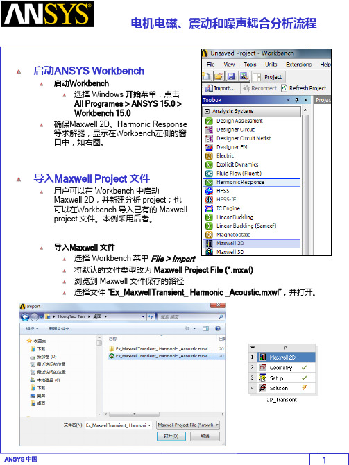
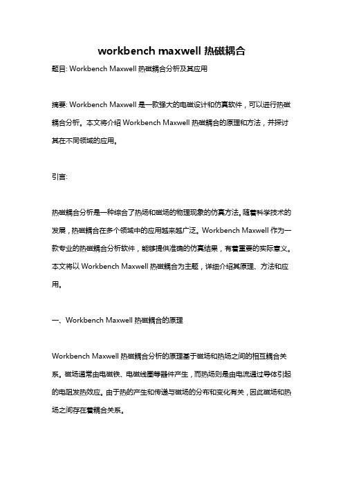
分析模型为 Prius 电机的二维分析模型。 瞬态分析模型的各项设置已经设置好。 如需要详细了解如何设置电机的瞬态分析模型,请查看其他相关培训文件。
定子铁心
Phase C Phase B 转子 轴 Phase A Phase C
磁钢
Maxwell 模型修改
为了精确分析定子齿部的径向电磁力,并将力密度的分布耦合到后续的谐响应分 析中。需要将定子齿部“分割”出来,并施加更细密的网格剖分。
调整仿真时间与步长
双击 Projects 管理窗口上的 Analysis>Setup1 设置仿真停止时间 Stop Time 为10ms 设置时间步长 Time Step 为 50us 点击 OK
激活瞬态电磁场与谐响应分析的耦合分析选项
激活瞬态电磁场与谐响应分析耦合分析选项 点击菜单Maxwell2D > Enable Harmonic Force Calculation 在弹出的Enable Harmonic Force Coulping 窗口中, 1. 选中Enable Force Calculation, 2. 在每一个齿尖模型的选择框中,打勾如下图。 3. 点击 OK 。 Maxwell将会在最后一个完整周期, 计算每一个选中物体的瞬时电磁力, 并通过傅里叶分析,转化成频域的 电磁力数据,频率范围是从直流到 DC to 1/(2*dT).
在弹出的 Element Length Based Refinement 窗口中, 1. 将 Name 改成 Length_ToothTips 2. Restrict length of Elements: 3. Maximum Length of Elements: 0.25 mm 4. 点击 OK 改善曲线网格剖分 选中所有的物体( Ctrl + A) 点击菜单 Maxwell 2D > Mesh Operations > Assign > Surface
Workbench有限元静力学分析.ppt
固定不变的载荷和响应是一种假定,即假定载荷和 结构相应随时间的变化非常缓慢。
2.1 结构静力分析简介
静力分析所施加的载荷类型有
外部施加的作用力和压力 稳态的惯性力 强迫位移 温度载荷 能流
2.2 结构线性静力分析基本步骤
2.2.4 结构线性静力分析实例1
GUI分析步骤 b. 模型剖分
5)模型剖分:为了对应力集中区域进行较准确的捕捉,划分 有限元网格之前,通常需要对几何模型进行适当的剖分,以 利于网格的划分。选择Utility Menu>WorkPlane>Display Working Plane,然后选择Utility>WorkPlane>Offset WP by Increments,在Offset WP对话框的Degrees框中输入:0,-90,0 然后点击OK确定。
Basic>Analysis Options:选择Small Displacement Static Sol’n Option选项指定采用的求解器 实际上,求解控制对话框的绝大多数默认选项对于静力线性分
析是合适的,用户只需要作很少的设置。
2.2 结构线性静力分析基本步骤
2.2.2 施加载荷并求解
2.2 结构线性静力分析基本步骤
2.2.1 建模
选择的材料特性可以是线性或者是非线性,可以是各 向同性或者各向异性材料,并且可以随温度变化或者 与温度无关。
GUI: Main Menu>Preprocessor>Material Props>-ConstantIsotropic/Orthotropic
选项获得结果数据,如应力和应变等。
ansys maxwell+workbench 2021 电机多物理场耦合
ansys maxwell+workbench 2021 电机多物理场耦合1. 引言1.1 概述本文旨在介绍ANSYS Maxwell+Workbench 2021在电机多物理场耦合方面的应用。
随着现代电力技术的迅猛发展,电机在各个领域中扮演着重要角色。
然而,电机设计与优化面临着许多复杂的问题,包括电磁场、结构和热场等多种物理场的相互影响。
因此,通过使用ANSYS Maxwell+Workbench工具来实现电机多物理场耦合模拟是一种有效的方法。
1.2 文章结构本文将分为五个部分进行阐述。
首先,在引言部分进行概述,并介绍文章结构。
第二部分将简要介绍ANSYS Maxwell+Workbench 2021工具的基本背景和功能特点。
接下来的第三部分将解析电机多物理场耦合的概念和原理,以便读者更好地了解该主题。
第四部分将重点介绍ANSYS Maxwell+Workbench在电机多物理场耦合中的应用,包括Maxwell在电磁场建模中的应用以及Workbench 在结构和热场建模中的应用,并通过实例讲解详细说明其使用方法。
最后,在第五部分对实验结果进行总结与分析,并展望该领域未来的发展趋势和应用前景。
1.3 目的本文的目的是向读者介绍ANSYS Maxwell+Workbench 2021工具在电机多物理场耦合中的应用。
通过了解该工具的基本背景、功能特点以及原理,读者能够更好地了解电机设计优化过程中多物理场相互耦合的问题,并学习如何使用ANSYS Maxwell+Workbench进行模拟和分析。
希望该文章能为电机设计和优化提供一定的指导,并对相关领域的研究人员和工程师有所帮助。
2. ANSYS Maxwell+Workbench 2021简介:2.1 ANSYS Maxwell简介:ANSYS Maxwell是一款电磁场仿真软件,旨在帮助工程师和设计师将电磁设计与虚拟原型建模相结合。
它提供了广泛的功能和工具,用于建模、分析和优化各种设备和系统中的电磁场问题。
学会使用AnsysWorkbench进行有限元分析和结构优化
学会使用AnsysWorkbench进行有限元分析和结构优化Chapter 1: Introduction to Ansys WorkbenchAnsys Workbench是一款广泛应用于工程领域的有限元分析和结构优化软件。
它的功能强大,能够帮助工程师在设计过程中进行力学性能预测、应力分析以及结构优化等工作。
本章节将介绍Ansys Workbench的基本概念和工作流程。
1.1 Ansys Workbench的概述Ansys Workbench是由Ansys公司开发的一套工程分析软件,主要用于有限元分析和结构优化。
它集成了各种各样的工具和模块,使得用户可以在一个平台上进行多种分析任务,如结构分析、热分析、电磁分析等。
1.2 Ansys Workbench的工作流程Ansys Workbench的工作流程通常包括几个基本步骤:(1)几何建模:通过Ansys的几何建模功能,用户可以创建出需要分析的结构的几何模型。
(2)加载和边界条件:在这一步骤中,用户需要为结构定义外部加载和边界条件,如施加的力、约束和材料特性等。
(3)网格生成:网格生成是有限元分析的一个关键步骤。
在这一步骤中,Ansys Workbench会将几何模型离散化为有限元网格,以便进行分析计算。
(4)材料属性和模型:用户需要为分析定义合适的材料属性,如弹性模量、泊松比等。
此外,用户还可以选择适合的分析模型,如静力学、动力学等。
(5)求解器设置:在这一步骤中,用户需要选择适当的求解器和设置求解参数,以便进行分析计算。
(6)结果后处理:在完成分析计算后,用户可以对计算结果进行后处理,如产生应力、位移和变形等结果图表。
Chapter 2: Finite Element Analysis with Ansys Workbench本章将介绍如何使用Ansys Workbench进行有限元分析。
我们将通过一个简单的示例,演示有限元分析的基本步骤和方法。
workbench电机电磁场有限元分析

Workshop
1
2
10/1/2004
2
ANSYS v9.0
Motor Analysis in the Workbench Environment
You should see an end view of the motor geometry. Using the left mouse button (LMB) click on the blue dot adjacent to the triad in the lower right corner of the plot. This should result in the isometric view shown at right.
10/1/2004
Workshop
3
ANSYS v9.0
Motor Analysis in the Workbench Environment
1) Bring up the enclosure tool as
shown at right. This will be used to automatically create a
The image can be dynamically rotated as follows:
1) Position the mouse cursor on the display
2) Hold down the middle mouse button (MMB)
3) Move the mouse cursor
After editing the details, right click on “Air” in the tree. In the drop down list that appears, left click on “Generate”. This will create a cylindrical volume of magnetic domain in which to immerse the imported parts.
workbench maxwell热磁耦合
workbench maxwell热磁耦合题目: Workbench Maxwell热磁耦合分析及其应用摘要: Workbench Maxwell是一款强大的电磁设计和仿真软件,可以进行热磁耦合分析。
本文将介绍Workbench Maxwell热磁耦合的原理和方法,并探讨其在不同领域的应用。
引言:热磁耦合分析是一种综合了热场和磁场的物理现象的仿真方法。
随着科学技术的发展,热磁耦合在多个领域中的应用越来越广泛。
Workbench Maxwell作为一款专业的热磁耦合分析软件,能够提供准确的仿真结果,有着重要的实际意义。
本文将以Workbench Maxwell热磁耦合为主题,详细介绍其原理、方法和应用。
一、Workbench Maxwell热磁耦合的原理Workbench Maxwell热磁耦合分析的原理基于磁场和热场之间的相互耦合关系。
磁场通常由电磁铁、电磁线圈等器件产生,而热场则是由电流通过导体引起的电阻发热效应。
由于热的产生和传递与磁场的分布和变化有关,因此磁场和热场之间存在着耦合关系。
Workbench Maxwell通过求解Maxwell方程组和热传导方程,实现热磁耦合的分析。
Maxwell方程组描述了磁场的分布和变化,包括麦克斯韦方程和电磁介质的本构关系。
热传导方程则描述了热场的传输过程,包括热传导的热量传递和温度分布。
通过将这两个方程组耦合,可以描述磁场和热场的相互作用,并得出准确的仿真结果。
二、Workbench Maxwell热磁耦合的方法1. 几何建模: 首先需要进行几何建模,包括导体、电磁铁和其他磁场和热场相关的器件。
使用Workbench Maxwell提供的建模工具,可以快速准确地构建几何模型。
2. 材料建模: 然后需要对材料进行建模,包括选择适当的导体材料和磁性材料,并设定其相应的热学和磁学参数。
Workbench Maxwell提供了广泛的材料库,用户可以根据需要选择合适的材料。
基于ANSYS Workbench平台的电机电磁噪声仿真分析
基于ANSYS Workbench平台的电机电磁噪声仿真分析电动机与发电机等电力设备的噪声起因很多,有电磁振动噪声、机械噪声及流致噪声等等,本文通过ANSYS公司的官方案例为操作背景,详细介绍如何将作用在定子上的瞬态电磁力作为结构谐响应分析的载荷计算振动噪声。
1.电磁模型建立与分析如图1所示为一个电机模型,电机的额定输出功率为550W,额定电压为220V,极对数为4,定子齿数为24个,转子的转速为1500rpm,求电磁振动产生的噪声大小。
本算例使用的模块如下:RMxprt模块:建立电机类型;Maxwell模块:2D瞬态电磁场计算;Structural模块:3D谐响应分析计算;Acoustics ACT模块:噪声计算注:Acoustics ACT模块需要单独安装,请用户到官方网站上自行下载。
图1电机模型电机的电路模型如图2所示。
图2电机电路模型1)启动Workbench。
在Windows XP下单击“开始”→“所有程序”→ANSYS15→Workbench 15命令,即可进入Workbench主界面。
2)保存工程文档。
进入Workbench后,单击工具栏中的按钮,将文件保存为“zhendongzaosheng.wbpj”,单击Getting Started窗口右上角的(关闭)按钮将其关闭。
3)双击Toolbox→Analysis System→RMxprt模块建立项目A,如图3所示。
4)双击项目A中的A1栏进如RMxprt电机设置平台,如图4所示。
图3RMxprt模块图4RMxprt平台5)依次选择菜单RMxprt→Machine Type,在弹出的电机类型选择对话框中单击Generic Rotating Machine选项,单击OK按钮,如图5所示。
6)单击Project Manager→RMxprt→Machine选项,在下面出现属性设置对话框中作如下设置:在Source Type栏中选择AC选项;在Structure栏中选择Inner Rotor选项;在Stator Type栏中选择SLOT_AC选项;在Rotor Type栏中选择PM_INTERIOR选项,如图6所示。
电磁场问题的有限元分析
ANSYS电磁场分析首先求解出电磁场的磁势和电势, 然后经后处理得到其他电磁场物理量,如磁力线分布、磁 通量密度、电场分布、涡流电场、电感、电容以及系统能 量损失等
● 电力发电机 ● 变压器 ● 电动机 ● 天线辐射 ● 等离子体装置
9.1 电磁场基本理论
(4)ANSYS电磁场分析简介 2. ANSYS电磁场分析方法 (2)建立分析模型。 在建立几何模型后,对求解区域用选定的单元进行划分, 并对划分的单元赋予特性和进行编号。 单元划分的疏密程度要根据具体情况来定,即在电磁 场变化大的区域划分较密,而变化不大的区域可划分得稀 疏些。 (3)施加边界条件和载荷。 (4)求解和后处理。
过滤图形用户界面进入电磁场 分析环境。在ANSYS软件的 Multiphysics模块中,执行:Main Menu>Preferences,在弹出的对话 框中选择多选框“Magnetic-Nodal” 后,单击[OK]。
9.2 二维静态磁场分析
(2)二维静态磁场分析实例 (2) 建立模型 ①生成大圆面:Main Menu>Preprocessor>Modeling>Create>Area >Circle>By Dimensions弹出如对话框,在对 话框中输入大圆的半径“6”.然后单击 [OK]。 ②生成小圆: MainMenu>Preprocessor>Modeling>Create>Areas>Ci rcle>Solid Circle,弹出一个对话框,在“WP X”后面 输入“1”,在“Radius”后面输入“2”,单击[OK], 则生成第第二个圆。 ③布尔操作: MainMenu>Preprocessor>Modeling>Cr eate>Booleans>Overlap>Area,在弹出 对话框后,单击[Pick All]。
基于ANSYS WORKBENCH的装配体有限元分析
基于ANSYS WORKBENCH的装配体有限元分析模拟装配体的本质就是设置零件与零件之间的接触问题。
装配体的仿真所面临的问题包括:(1)模型的简化。
这一步包含的问题最多。
实际的装配体少的有十几个零件,多的有上百个零件。
这些零件有的很大,如车门板;有的体积很小,如圆柱销;有的很细长,如密封条;有的很薄且形状极不规则,如车身;有的上面钻满了孔,如连接板;有的上面有很多小突起,如玩具的外壳。
在对一个装配体进行分析时,所有的零件都应该包含进来吗?或者我们只分析某几个零件?对于每个零件,我们可以简化吗?如果可以简化,该如何简化?可以删除一些小倒角吗?如果删除了,是否会出现应力集中?是否可以删除小孔,如果删除,是否会刚好使得应力最大的地方被忽略?我们可以用中面来表达板件吗?如果可以,那么,各个中面之间如何连接?在一个杆件板件混合的装配体中,我们可以对杆件进行抽象吗?或者只是用实体模型?如果我们做了简化,那么这种简化对于结果造成了多大的影响,我们可以得到一个大致的误差范围吗?所有这些问题,都需要我们仔细考虑。
(2)零件之间的联接。
装配体的一个主要特征,就是零件多,而在零件之间发生了关系。
我们知道,如果零件之间不能发生相对运动,则直接可以使用绑定的方式来设置接触。
如果零件之间可以发生相对运动,则至少可以有两种选择,或者我们用运动副来建模,或者,使用接触来建模。
如果使用了运动副,那么这种建模方式对于零件的强度分析会造成多大的影响?在运动副的附近,我们所计算的应力其精确度大概有多少?什么时候需要使用接触呢?又应该使用哪一种接触形式呢?(3)材料属性的考虑。
在一个复杂的装配体中所有的零件,其材料属性多种多样。
我们在初次分析的时候,可以只考虑其线弹性属性。
但是对于高温,重载,高速情况下,材料的属性不再局限于线弹性属性。
此时我们恐怕需要了解其中的每一种材料,它是超弹性的吗?是哪一种超弹性的?它发生了塑性变形吗?该使用哪一种塑性模型?它是粘性的吗?它是脆性的吗?它的属性随着温度而改变吗?它发生了蠕变吗?是否存在应力钢化问题?如此众多的零件,对于每一个零件,我们都需要考察其各种各样的力学属性,这真是一个丰富多彩的问题。
ANSYSWorkbench电磁场分析例子ppt课件
© 2004 ANSYS, Inc.
ANSYS, Inc. Proprietary
Enclosure Symmetry
•Feature: The Enclosure feature now supports symmetry models when the enclosure shape is a box or a cylinder: • Up to 3 three symmetry planes can be specified. • Full or partial models can be included in the Enclosure. • During the model transfer from DesignModeler to Simulation, the enclosure feature with symmetry planes forms two kinds of named selections: • Open Domain • Symmetry Plane
• Benefits: Very easy to use, rapid creation of coil windings.
© 2004 ANSYS, Inc.
ANSYS, Inc. Proprietary
Winding Bodies
Tangent orientation vector (blue arrow) defines direction of current.
• Coils may have different radii between IN & OUT slots • Multiple coils may be stacked in the same slot
- 1、下载文档前请自行甄别文档内容的完整性,平台不提供额外的编辑、内容补充、找答案等附加服务。
- 2、"仅部分预览"的文档,不可在线预览部分如存在完整性等问题,可反馈申请退款(可完整预览的文档不适用该条件!)。
- 3、如文档侵犯您的权益,请联系客服反馈,我们会尽快为您处理(人工客服工作时间:9:00-18:30)。
10/1/2004
9.0 New Features
3
ANSYS v9.0
Motor Analysis in the Workbench Environment
Workshop
1) Bring up the enclosure tool as shown at right. This will be used to automatically create a mesh of the magnetic domain between and surrounding the imported geometry 2) Note the details that appear in the lower left pane after this selection is made. We will edit these default values.
Workshop
Setting clash detection to “yes” will bring up another row called “Bodies for Clash Detection” in the winding details pane. Click the cell to the right, highlight “rotor” in the tree, and click Apply. This will trigger a check for interference between the defined windings and the rotor stack.
Workshop
2
10/1/2004
9.0 New Features
7
ANSYS v9.0
Motor Analysis in the Workbench Environment
Use the Winding Tool Editor to bring up the “winding details” and “winding table” panes shown in the red boxes at right.
Workshop
2
10/1/2004
9.0 New Features
14
ANSYS v9.0
Motor Analysis in the Workbench Environment
Once the geometry is successfully attached in Design Simulation, define the current and phase angles for conductors A, B, and C as shown at right: Conductor A: 55 A 0 Conductor B: 55 A 120 Conductor C: 55 A 240 1
Workshop
1
2
10/1/2004
9.0 New Features
8
ANSYS v9.0
Motor Analysis in the Workbench Environment
In the winding details pane, click on the cell to the right of “Center Plane”, then select Plane6 from the tree, then click apply (step 3 at right). This positions/orients the windings so that predefined plane6 is the winding midplane. 2
Workshop
10/1/2004
9.0 New Features
12
ANSYS v9.0
Motor Analysis in the Workbench Environment
One nice way to visualize the windings is to right click on rotor in the tree and choose “Hide All Other Bodies” in the drop down list. Then, in the tree, click on any of the 6 individual coils comprising the winding (A.1, A.2, B.1, B.2, C.1, C.2). For example, the location of coil A.1 is shown below.
5
ANSYS v9.0
Motor Analysis in the Workbench Environment
After editing the details, right click on “Air” in the tree. In the drop down list that appears, left click on “Generate”. This will create a cylindrical volume of magnetic domain in which to immerse the imported parts.
Workshop
1
3 2
10/1/2004
9.0 New Features
13
ANSYS v9.0
Motor Analysis in the Workbench Environment
Now click on the Project tab and choose “New Simulation” 1
Workshop
3: Click “Apply”
1
10/1/2004
9.0 New Features
9
ANSYS v9.0
Motor Analysis in the Workbench Environment
A winding table text file containing information describing the rotor coils (winding.txt) is in the local working directory. Read the table as shown at right. Click the cell to the right of “winding Table File” in the winding details pane and click on “…” to browse for the file.
Workshop
2
10/1/2004
9.0 New Features
15
ANSYS v9.0
Motor Analysis in the Workbench Environment
Prepare to define magnetic flux parallel boundaries on the exterior of the modeled domain as shown at right.
1
2
10/1/2004
9.0 New Features
2
ANSYS v9.0
Motor Analysis in the Workbench Environment
Workshop
You should see an end view of the motor geometry. Using the left mouse button (LMB) click on the blue dot adjacent to the triad in the lower right corner of the plot. This should result in the isometric view shown at right.
9.0 New Features
Work Bench Environment
Low Frequency Electromagnetic Analysis of Motors
ANSYS v9.0
Motor Analysis in the Workbench Environment
Workshop
Upon entering the workbench environment, read in the design modeler geometry stored in motor2_base.agdb.
Workshop
2
3
1
10/1/2004
9.0 New Features
10
ANSYS v9.0
Motor Analysis in the Workbench Environment
Once the file is read in, make the following additional changes in the winding details pane: • • FD2: Slot Angle => 22.5 Clash Detection? => Yes
1
2
10/1/2004
9.0 New Features
4
ANSYS v9.0
Motor Analysis in the Workbench Environment
Click on the individual entries in the right hand column of the details pane and edit them as shown below.
The image can be dynamically rotated as follows: 1) Position the mouse cursor on the display 2) Hold down the middle mouse button (MMB) 3) Move the mouse cursor