凌华AMP208C控制板卡调试说明书
208H系统调试说明书8页word文档

停车场设备接线及调试说明书208H型(422)Develop High-tech Limited Company成都新纪元高科技发展有限公司目录一.设备简介 (2)二.208H型停车设备详细配置 (2)三.设备系统控制图 (2)四、设备组成及功能简介 (2)4-2、出口刷卡票箱EP-DK06 (2)4-4. 设备主要通讯工具及接口 (3)五、设备接线方法 (3)5-2.道闸机控制器的接线方法 (3)208H道闸控制器接线端顺序图 (4)5-3、接口功能定义 (4)5-4、LED显示屏连接示意图 (4)六、设备调试方法 (5)七、停车场软件设备设置方法 (5)八、停车场系统设置 (6)九、软件里设备十六进制换算十进制地址方法 (6)十、常见故障 (7)一.设备简介208H道闸系统是由成都新纪元高科技发展有限公司自主研发及生产的智能停车系统,系统设计安全可靠,配有语音提示和指示灯向导,使客户操作更加简单。
该设备目前主要包含道闸机、车检器、发卡机、LED显示屏等其它可扩充产品。
该设备是目前市面上最先进的智能停车系统之一,拥有智能卡识别功能、蓝牙识别功能、地感识别功能、红外控制功能及强大的管理员设置功能。
二.208H型停车设备详细配置2-1.入口设备发卡机:发卡机芯、LED显示屏、读卡器、12V电源及箱体道闸机:减速箱、电机、控制器、闸杆及箱体2-2. 出口设备出口票箱:LED显示屏、读卡器、12V电源及箱体道闸机:减速箱、电机、控制器、闸杆及箱体2-3. 中控设备网络控制器、视频采集卡三.设备系统控制图3-1.设备外观安装实例3-2.设备布线示意图3-3系统设备布线方法注:设备422通讯布线方法(道闸机为208H型控制器)1、将出入口设备用网线串接起来,如422通讯网线从入口票箱与出口票箱串接后,再从出口票箱串接到电脑。
2、入口票箱接一根网线到入口道闸,出口票箱接一根网线到出口道闸机。
(注:系统需要接的线主要是票箱之间的422通讯线及票箱和道闸机之间的控制线。
APM-204C_208C MCPRO2使用手册
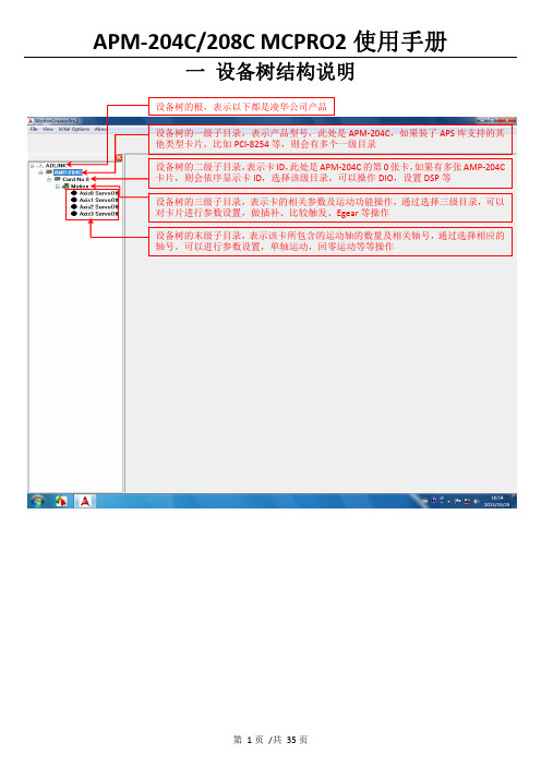
一 设备树结构说明二 设备树目录对应的菜单项及工具栏2.1 根目录及一级子目录(AMP ‐204C 子目录)2.1.1 对应菜单1、Initial Options 菜单项2、About 菜单项该菜单项用于获取MCPRO2版本信息、数据库版本信息及MCPRO2所支持的产品信息等等。
3、根目录右键菜单当选择ADLINK 根目录,右键点击,弹出保存/载入所有参数菜单,如下所示2.2 二级子目录(Card No 0子目录)2.2.1对应菜单及工具栏当选中相应的卡ID 目录(例如Card No 0),会弹出如下DIO 和DSP 操作菜单及工具栏2.2.2 右键菜单当选中相应的卡ID2.3 三级子目录(Motion 子目录)2.3.1对应工具栏2.3.2对应菜单栏2.3.3 右键菜单当选中相应卡ID 目录(例如Card No 0)下的Motion ,右击 会弹出如下右键菜单ServoOn 该卡下面的所有轴ServoOff 该卡下面的所有轴2.4 末级子目录(单轴操作子目录)2.4.1对应工具栏当选中相应的轴号时,会弹出如下工具栏2.4.2对应菜单栏2.4.3 右键菜单三 MCPRO2操作3.1 设置向导(SetupWizard )选择要操作的轴,在工具栏点击SetupWizard 按钮,弹出SetupWizard 对话框。
如下图示。
Step 1:Control Mode (控制模式)该步骤用于设置板卡控制模式及伺服更新率。
但是为防止客户误操作,控制模式设置和伺服更新率设置被移出该步骤。
如果要设置,请参考下面的设置。
1、选择要操作的轴2、点击SetupWizard按钮3、弹出SetupWizard对话框1、更改控制模式:注意:请根据每个轴使用的电机类型来设置每个轴的控制模式,控制模式一旦设定,请勿随意变更。
1、先选择Motion 子目录点击此按钮保存设置2、设置伺服更新率:以下两种方式都可以设置伺服更新率: 方式1:方式2:注意:如非必要,请勿随意更改伺服更新率。
SM2082C单通道LED线性恒流驱动控制芯片
I LED * t V
公式中,ILED 为整个方案中的恒流电流,时间 t :在 50Hz 时约为 (1/4)*(1/fAC) = 5ms,ΔV 是 OUT 端口电压纹波。 芯片并联应用方案
1 OUT 2 GND 3 REXT Rext1
SM2082C
SM2082C SM2082C SM2082C
LED1 C1 LED2 LEDn
220V~
LED灯管
1 OUT 2 GND 3 REXT Rext
C2
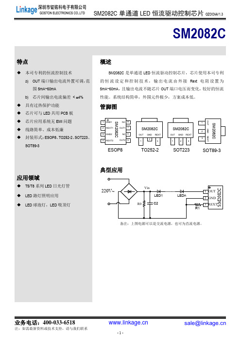
图 5 SM2082C 典型应用电路—交流电源输入
瓷片电容 C1 的容值由 AC 源电压和 LED 灯管中串接的 LED 数量 n 决定, 一般可取 0uF ~ 4.7uF。 当 LED 灯数 量串联的足够多时不需要使用 C1 电容。 电解电容 C2 值越大,电压 Vin 纹波越小,SM2082C OUT 端口电压纹波越小。C2 值根据 LED 灯管总工作电 流而定:电流越大,C2 容值越大,一般取值 4.7uF/400V~22uF/400V。具体计算方法如下: 滤波电容 C2 容值: C 2
OUT
1 2 3 4 GND1 REXT1 GND2 REXT2 NC 8 OUT1 7 NC 6 OUT2 5
概述
SM2082C 是单通道 LED 恒流驱动控制芯片,芯片使用本司专利 的 恒 流 设 定 和 控 制 技 术 , 输 出 电 流 由 外 接 Rext 电 阻 设 置 为 5mA~60mA, 且输出电流不随芯片 OUT 端口电压而变化, 较好的恒流 性能。系统结构简单,外围元件极少,方案成本低。
业务电话:400-033-6518
注:如需最新资料或技术支持,请与我们联系
-6-
sale@
Moxa EDS-208系列产品说明书

P/N: 1802002080016*1802002080016*EDS-208 Series Quick Installation GuideMoxa EtherDevice SwitchVersion 5.2, January 2021Technical Support Contact Information/support2021 Moxa Inc. All rights reserved.OverviewThe EDS-208 series of Moxa EtherDevice™ Switches are entry-level8-port Ethernet Switches that provide a cost-effective solution for industrial Ethernet connections. EDS-208 provides a choice of 12 to 48 VDC power input. The switches can operate reliably in a temperature range of -10 to 60°C, and the rugged hardware design makes EDS-208 perfect for ensuring that your Ethernet equipment can be used in demanding industrial environments.Package ChecklistMoxa EDS-208 is shipped with the following items. If any of these items is missing or damaged, please contact your customer service representative for assistance.• 1 EDS-208 or EDS-208-M-SC or EDS-208-M-ST•Quick installation guide (printed)•Warranty cardFeaturesHigh Performance Network Switching Technology•10/100BaseT(X) (RJ45), 100BaseFX (SC/ST type, Multi-mode) •IEEE 802.3/802.3u/802.3x•Store and Forward switching process type, 1024 address entries Industrial Design•Operating temperature ranges from -10 to 60°C•Power inputs: 12 to 48 VDC•IP30, plastic case•DIN-Rail mounting abilityPanel Layout of EDS-2081.Heat dissipation orifices2.Terminal block for power inputand grounding3.Moxa Logo4.Power input LED5.10/100BaseT(X) Port6.TP port’s 100 Mbps LED7.TP port’s 10 Mbps LED8.DIN-Rail kitPanel Layout of EDS-208-M-SC/ST1.Heat dissipation orifices2.Terminal block for power inputand grounding3.Moxa Logo4.Power input LED5.10/100BaseT(X) Port6.TP port’s 100 Mbps LED7.TP port’s 10 Mbps LED8.FX port’s 100 Mbps LED9.100BaseFX Port10.DIN-Rail kitMounting Dimensions (unit = mm)DIN-Rail MountingThe plastic DIN-Rail attachment plate should already be fixed to the rear panel of EDS-208 when you take it out of the box. If you need to reattach the DIN-Rail attachment plate to EDS-208, make sure the DIN-Rail kit is situated towards the top, as shown in the figures below.STEP 1: Insert the top of the DIN-Rail into the slot. STEP 2:The DIN-Rail attachment unit will snap into place as shown below.To remove Moxa EDS-208 from theDIN-Rail, insert a flat-blade screwdriver horizontally into the DIN-Railkit under the EDS-208, and thenpull it upwards and releaseEDS-208 towards you away fromthe DIN-Rail.You may also take the following steps to remove the EDS-208 from the DIN-Rail.STEP 1: Press the middle of the flat side of the mounting kit as indicated. Pull the EDS-208 downwards.STEP 2:Release it towards you and away from the DIN-Rail.Wiring RequirementsYou should also pay attention to the following items:• Use separate paths to route wiring for power and devices. If powerwiring and device wiring paths must cross, make sure the wires are perpendicular at the intersection point.NOTE: Do not run signal or communications wiring and power wiring in the same wire conduit. To avoid interference, wires with different signal characteristics should be routed separately.• You can use the type of signal transmitted through a wire todetermine which wires should be kept separate. The rule of thumb is that wiring that shares similar electrical characteristics can bebundled together.• Keep input wiring and output wiring separated.•It is strongly advised that you label wiring to all devices in the system when necessary.Grounding EDS-208Grounding and wire routing help limit the effects ofnoise due to electromagnetic interference (EMI).Run the ground connection from the right mostcontact of the 3-contact terminal block to thegrounding surface prior to connecting devices.Wiring the Power InputsThe two left-most contacts of the 3-contact terminal block connector on EDS-208’s top panel are used for the DC input. Top and front views of one of the terminal block connectors are shown here.STEP 1: Insert the negative/positive DC wires intothe V-/V+ terminals.STEP 2: To keep the DC wires from pulling loose,use a small flat-blade screwdriver to tighten thewire-clamp screws on the front of the terminalblock connector.STEP 3: Insert the plastic terminal block connectorprongs into the terminal block receptor, which islocated on EDS’s top panel.Communication ConnectionsEDS-208 has 7 or 8 10/100BaseT(X) Ethernet ports, and 1 or 0 (zero) 100BaseFX (SC/ST-type connector) multi-mode fiber ports.10/100BaseT(X) Ethernet Port ConnectionThe 10/100BaseT(X) ports located on EDS-208’s front panel are used to connect to Ethernet-enabled devices.Below we show pinouts for both MDI (NIC-type) ports and MDI-X (HUB/Switch-type) ports, and also show cable wiring diagrams for straight-through and cross-over Ethernet cables.MDI Port PinoutsMDI-X Port Pinouts 8-pin RJ45 PinSignal 1Tx+ 2Tx- 3Rx+ 6 Rx- PinSignal 1Rx+ 2 Rx- 3 Tx+ 6 Tx-RJ45 (8-pin) to RJ45 (8-pin) Straight-Through Cable WiringRJ45 (8-pin) to RJ45 (8-pin) Cross-Over Cable Wiring100BaseFX Ethernet Port ConnectionThe concept behind the SC/ST port and cable is quite straightforward. Suppose you are connecting devices I and II. Contrary to electrical signals, optical signals do not require a circuit in order to transmit data.Consequently, one of the optical lines is used to transmit data from device I to device II, and the other optical line is used to transmit data from device II to device I, for full-duplex transmission.All you need to remember is to connect the Tx (transmit) port of device I to the Rx (receive) port of device II, and the Rx (receive) port of device I to the Tx (transmit) port of device II. If you make your own cable, we suggest labeling the two sides of the same line with the same letter (A-to-A and B-to-B, as shown below, or A1-to-A2 and B1-to-B2). SC-Port Pinouts SC-Port to SC-Port Cable WiringST-Port Pinouts ST-Port to ST-Port Cable WiringLED IndicatorsThe front panel of EDS-208 contains several LED indicators. The function of each LED is described in the table below.LED Color State DescriptionP AMBER OnPower is being supplied to the powerinputOffPower is not being supplied to thepower input10(TP) GREENOn TP port’s 10 Mbps link is active Blinking Data is being transmitted at 10 Mbps Off TP Port’s 10 Mbps link is inactive100(TP) GREENOn TP port’s 100 Mbps link is active BlinkingData is being transmitted at 100MbpsOff 100BaseTX Port’s link is inactive100M(FX) GREENOn FX port’s 100 Mbps link is active BlinkingData is being transmitted at 100MbpsOff 100BaseFX Port’s link is inactiveAuto MDI/MDI-X ConnectionThe Auto MDI/MDI-X function allows users to connect EDS-208’s10/100BaseTX ports to any kind of Ethernet device, regardless of how the Ethernet cable is wired. This means that you can use either astraight-through cable or cross-over cable to connect EDS-208 to Ethernet devices.Dual Speed Functionality and SwitchingEDS208’s 10/100 Mbps switched RJ45 port auto negotiates with the connected device for the fastest data transmission rate supported by both devices. All models of EDS-208 are plug-and-play devices, so that software configuration is not required at installation, or during maintenance. The half/full duplex mode for the switched RJ45 ports is user dependent and changes (by auto-negotiation) to full or half duplex, depending on which transmission speed is supported by the attached device.Switching, Filtering, and ForwardingEach time a packet arrives at one of the switched ports, a decision is made either to filter or to forward the packet. Packets with source and destination addresses belonging to the same port segment will be filtered, constraining those packets to one port, and relieving the rest of the network from the need to process them. A packet with destination address on another port segment will be forwarded to the appropriate port, and will not be sent to the other ports where it is not needed. Packets that are used in maintaining the operation of the network (such as the occasional multi-cast packet) are forwarded to all ports.EDS-208 operates in the store-and-forward switching mode, which eliminates bad packets and enables peak performance to be achieved when there is heavy traffic on the network.Switching and Address LearningEDS-208 has an address table that can hold up to 1,000 node addresses, which makes it suitable for use with large networks. The address tables are self-learning, so that as nodes are added or removed, or moved from one segment to another, EDS-208 automatically keeps up with new node locations. An address-aging algorithm causes the least-used addresses to be deleted in favor of newer, more frequently used addresses. To reset the address buffer, power down the unit and then power it back up. Auto-Negotiation and Speed SensingAll of EDS-208’s RJ45 Ethernet ports independently supportauto-negotiation for speeds in the 10BaseT and 100BaseTX modes, with operation according to the IEEE 802.3u standard. This means that some nodes could be operating at 10 Mbps, while at the same time, other nodes are operating at 100 Mbps.Auto-negotiation takes place when a “live” RJ45 cable is connected to the switch, and then each time a LINK is enabled. EDS-208 advertises its capability for using either 10 Mbps or 100 Mbps transmission speeds, with the device at the other end of the cable expected to similarly advertise. Depending on what type of device is connected, this will result in agreement to operate at a speed of either 10 Mbps or 100 Mbps.If an EDS-208 RJ45 Ethernet port is connected to a non-negotiating device, it will default to 10 Mbps speed and half-duplex mode, as required by the IEEE 802.3u standard.SpecificationsTechnologyStandards IEEE802.3, 802.3u, 802.3xProcessing Type Store and Forward, with IEEE802.3x fullduplex, non-blocking flow controlAddress Table Size 1,000 uni-cast addressesInterfaceRJ45 Ports 10/100BaseT(X) auto negotiation speed, F/Hduplex mode, and auto MDI/MDI-X connection Fiber Ports 100BaseFX ports (SC/ST connector)LED Indicators Power, 10/100 M (TP port), 100 M (FX port) PowerInput Voltage 12 to 48 VDCInput Current @ 24 VDC 0.07 A (EDS-208)0.1 A (EDS-208-M-SC/EDS-208-M-ST) Connection Removable 3-contact Terminal Block Overload CurrentPresentProtectionPresentReverse PolarityProtectionMechanicalCasing IP30 protection, plastic caseDimensions 40 x 109 x 95 mm (W x H x D)Weight 170 gInstallation DIN-RailEnvironmentOperating Temperature -10 to 60°C (14 to 140°F) Storage Temperature -40 to 70°C (-40 to 158°F)5 to 95% (non-condensing) Ambient RelativeHumidityRegulatory ApprovalsSafety UL 508EMI FCC Part 15, CISPR 32 class A EMS EN61000-4-2 (ESD),EN61000-4-3 (RS),EN61000-4-4 (EFT),EN61000-4-5 (Surge),EN61000-4-6 (CS)Shock IEC 60068-2-27Free Fall IEC 60068-2-32Vibration IEC 60068-2-6 WARRANTY 5 years。
GCAN-208CAN光纤转换器用户手册

GCAN-208CAN光纤转换器⽤户⼿册GCAN-208CAN光纤转换器⽤户⼿册⽂档版本:V3.01 (2015/8/4)修订历史⽬录⽬录 (3)1. 功能简介 (4)1.1 功能概述 (4)1.2 性能特点 (4)1.3 典型应⽤ (5)2. 设备安装 (6)2.1 模块固定 (6)2.2 光纤连接 (8)2.3 与CAN总线连接 (8)3. 设备使⽤ (9)3.1 CAN总线配置 (9)3.2 与光纤连接 (10)3.3 与CAN连接 (10)3.4 CAN总线终端电阻 (11)3.5 系统状态指⽰灯 (11)4. 技术规格 (13)5. 常见问题 (14)附录CAN2.0B协议帧格式 (15)1. 功能简介1.1 功能概述沈阳⼴成科技有限公司GCAN-208模块是集成1路标准光纤接⼝(单模、多模,SC、ST可选)、2路标准CAN总线接⼝的⼯业级CAN总线转光纤转换器。
GCAN-208模块可以将CAN总线数据转换成光信号通过光纤传输。
通过成对使⽤GCAN-208模块,⽤户可以轻松的延长CAN总线通信距离、有效的消除长距离通信⼲扰,可以防⽌总线受到电磁⼲扰、地环⼲扰、雷击等对总线和设备造成的损坏。
GCAN-208模块可将CAN总线数据透明、⽆损的转换成光信号,再将光信号透明、⽆损的解析成CAN总线数据。
⼴成科技使⽤独有的总线信号转换技术,可将CAN数据与光信号之间的转换时间做到微秒级,这样就保证了通信的实时性,所以GCAN-208可⽀持任何CAN总线通信协议如:CANopen、SAE J1939、DeviceNet、NMEA2000等等。
GCAN-208模块独特的双通道设备可以同时延长两条CAN总线的通信距离,该模块是⼯业总线改造、长距离通信、隔离总线⼲扰的关键性⼯具,同时该模块具有体积⼩巧、即插即⽤等特点,也是现有系统集成的最佳选择。
GCAN-208模块的总线接⼝已集成隔离保护模块,使其避免由于瞬间的过压过流⽽对模块造成损坏。
AI208X系列温控表使用说明书
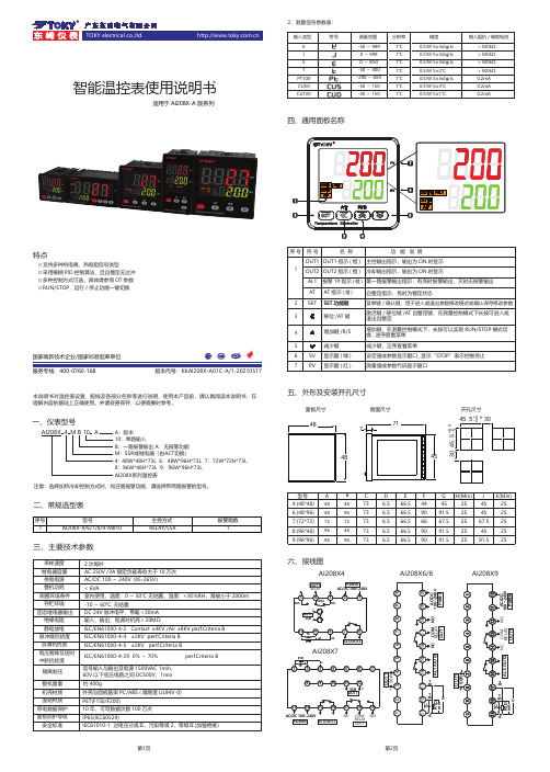
智能温控表使用说明书固态继电器输出绝缘电阻静电放电脉冲群抗扰度浪涌抗扰度电压暂降及短时中断抗扰度隔离耐压DC 24V 脉冲电平,带载<30mA 输入、输出、电源对机壳>20MΩIEC/EN61000-4-2 Contact ±4KV /Air ±8KV perf.Criteria B IEC/EN61000-4-4 ±2KV perf.Criteria B IEC/EN61000-4-5 ±2KV perf.Criteria BIEC/EN61000-4-29 0%~70% perf.Criteria B信号输入与输出及电源1500VAC 1min,60V 以下低压电路之间DC500V,1min整机重量约 400g机壳材质面贴材质停电数据保护面板防护等级安全标准外壳与面板基架PC/ABS (难燃度UL94V-0)PET(F150/F200)10年,可写数据次数100万次IP65(IEC60529)IEC61010-1 过电压分类Ⅱ,污染等级2,等级Ⅱ(加强绝缘)采样速度2次每秒供电电源继电器容量AC 250V /3A 额定负载寿命大于10万次AC/DC 100~240V (85-265V)一、仪表型号周围环境条件整机功耗存贮环境< 6VA室内使用,温度:0~50℃ 无结露,湿度:<85%RH,海拔小于2000m -10~60℃,无结露三、主要技术参数注意:选择加热冷却控制方式时,如还需报警功能,请选择带两路报警的型号。
国家高新技术企业/国家标准起草单位 版本代号:KKAI208X-A01C-A/1-20210517服务专线:400-0760-168适用于AI208X -A 版系列⊙支持多种热电偶、热电阻信号类型⊙采用模糊PID 控制算法,且自整定无过冲⊙多种控制方式可选,具体请参照OT 参数⊙RUN/STOP,运行/停止功能一键切换特点本说明书对温控表设置、配线及各部分名称等进行说明,使用本产品前,请认真阅读本说明书,在理解内容的基础上正确使用。
APM-204C_208C MCPRO2使用手册
一 设备树结构说明二 设备树目录对应的菜单项及工具栏2.1 根目录及一级子目录(AMP ‐204C 子目录)2.1.1 对应菜单1、Initial Options 菜单项2、About 菜单项该菜单项用于获取MCPRO2版本信息、数据库版本信息及MCPRO2所支持的产品信息等等。
3、根目录右键菜单当选择ADLINK 根目录,右键点击,弹出保存/载入所有参数菜单,如下所示2.2 二级子目录(Card No 0子目录)2.2.1对应菜单及工具栏当选中相应的卡ID 目录(例如Card No 0),会弹出如下DIO 和DSP 操作菜单及工具栏2.2.2 右键菜单当选中相应的卡ID2.3 三级子目录(Motion 子目录)2.3.1对应工具栏2.3.2对应菜单栏2.3.3 右键菜单当选中相应卡ID 目录(例如Card No 0)下的Motion ,右击 会弹出如下右键菜单ServoOn 该卡下面的所有轴ServoOff 该卡下面的所有轴2.4 末级子目录(单轴操作子目录)2.4.1对应工具栏当选中相应的轴号时,会弹出如下工具栏2.4.2对应菜单栏2.4.3 右键菜单三 MCPRO2操作3.1 设置向导(SetupWizard )选择要操作的轴,在工具栏点击SetupWizard 按钮,弹出SetupWizard 对话框。
如下图示。
Step 1:Control Mode (控制模式)该步骤用于设置板卡控制模式及伺服更新率。
但是为防止客户误操作,控制模式设置和伺服更新率设置被移出该步骤。
如果要设置,请参考下面的设置。
1、选择要操作的轴2、点击SetupWizard按钮3、弹出SetupWizard对话框1、更改控制模式:注意:请根据每个轴使用的电机类型来设置每个轴的控制模式,控制模式一旦设定,请勿随意变更。
1、先选择Motion 子目录点击此按钮保存设置2、设置伺服更新率:以下两种方式都可以设置伺服更新率: 方式1:方式2:注意:如非必要,请勿随意更改伺服更新率。
霍尼韦尔 伏卡安全系统 B208 八路输入模块操作指南说明书
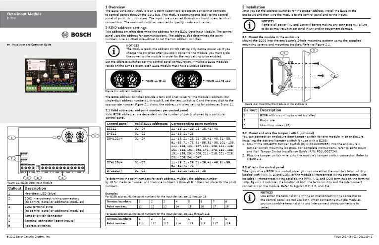
Callout Description1Heartbeat LED (blue)2SDI2 interconnect wiring connectors(to control panel or additional modules) 3SDI2 terminal strip(to control panel or additional modules) 4Tamper switch connector5Terminal connector (point inputs)6Address switches 1 OverviewThe B208 Octo-input Module is an 8 point supervised expansion device that connectsto control panels through the SDI2 bus. This module communicates back to the controlpanel all point status changes. The inputs are accessed through on-board screw terminalconnections. The on-board switches are used to specify module addresses.2 SDI2 address settingsTwo address switches determine the address for the B208 Octo-input Module. The controlpanel uses the address for communications. The address also determines the pointnumbers. Use a slotted screwdriver to set the two address switches.2.1 Valid addresses and point numbers per control panelValid B208 addresses are dependent on the number of points allowed by a particularcontrol panel.3 InstallationAfter you set the address switches for the proper address, install the B208 in theenclosure and then wire the module to the control panel and to the inputs.Control panel Valid B208 addresses Corresponding point numbersB551201 - 0411 - 18, 21 - 28, 31 - 38, 41 - 48B451201 - 0211 - 18, 21 - 28D9412GV401 - 2411 - 18, 21 - 28, 31 - 38, 41 - 48, 51 - 58,61 - 68, 71 - 78, 81 - 88, 91 - 98, 101 - 108,111 - 118, 121 - 127, 131 - 138, 141 - 148,151 - 158, 161 - 168, 171 - 178, 181 - 188,191 - 198, 201 - 208, 211 - 218, 221 - 228,231 - 238, 241 - 247D7412GV401 - 0711 - 18, 21 - 28, 31 - 38, 41 - 48, 51 - 58,61 - 68, 71 - 75D7212GV401 - 0311 - 18, 21 - 28, 31 - 38Figure 2.1: Address switchesTo determine the point numbers for each address, multiply the address numberby 10 for the base number, and then use numbers 1 through 8 in the ones place for the pointnumbers.ExamplesFor B208 address 01the point numbers for the input devices are 11 through 18:Terminal numbers12345678Point numbers1112131415161718For B208 address 11 the point numbers for the input devices are 111 through 118:Terminal numbers12345678Point numbers111112113114115116117118= Inputs 11 to 18= Inputs 111 to 118Set the address switches per the control panel confi guration. If multiple B208 modulesreside on the same system, each B208 module must have a unique address.NOTICE!The module reads the address switch setting only during power up. If youchange the switches after you apply power to the module, you must cyclethe power to the module in order for the new setting to be enabled.The B208 address switches provide a tens and ones value for the module’s address. Forsingle-digit address numbers 1 through 9, set the tens switch to 0 and the ones digit to theappropriate number. Figure 2.1 shows the address switches setting for addresses 9 and 11.3.1 Mount the module in the enclosureMount the B208 into the enclosure’s 3-hole mounting pattern using the suppliedmounting screws and mounting bracket. Refer to Figure 3.1.3.2 Mount and wire the tamper switch (optional)You can connect an enclosure door tamper switch for one module in an enclosure.Installing the optional tamper switch for use with a B208:1. Mount the ICP-EZTS Tamper Switch (P/N: F01U009269) into the enclosure’stamper switch mounting location. For complete instructions, refer to EZTS Coverand Wall Tamper Switch Installation Guide (P/N: F01U003734).2. Plug the tamper switch wire onto the module’s tamper switch connector. Refer toFigure 1.1.3.3 Wire to the control panelWhen you wire a B208 to a control panel, you can use either the module’s terminal striplabeled with PWR, A, B, and COM, or the module’s interconnect wiring connectors (wireincluded). Interconnect wiring parallels the PWR, A, B, and COM terminals on the terminalstrip. Figure 1.1 indicates the location of both the terminal strip and the interconnectconnectors on the module. Refer to Figures 3.2, 3.3, and 3.4.NOTICE!Use either the terminal strip wiring or interconnect wiring connector tothe control panel. Do not use both. When connecting multiple modules,you can combine terminal strip and interconnect wiring connectors inseries.Callout Description1B208 with mounting bracket installed2Enclosure3Mounting screws (3)Figure 1.1: B208 Octo-input Module NOTICE!Remove all power (AC and Battery) before making any connections. Failure to do so may result in personal injury and/or equipment damage.Callout Description1B208 Octo-input Module 2B208 sensor loops31 k Ω EOL resistor (ICP-1K22AWG-10)4Wiring to additional sensor loops3.4 Sensor Loop WiringWire resistance on each sensor loop must be less than 100 Ω with the detection devices connected. The terminal strip supports 12 to 22 AWG (0.65 to 2 mm) wires.The B208 detects open, short, normal, and ground fault circuit conditions on its sensor loops and transmits the conditions to the control panel. Each sensor loop is assigned a point number and transmits to the control panel individually. Run wires away from the premises telephone and AC wiring. Refer to Figure 3.5.4 LED descriptionsThe B208 Octo-input Module includes one blue heartbeat LED to indicate that the module has power and to indicate the module’s current state. Refer(GV4 Series control panel shown)Callout Description1Bosch control panel 2B208 Octo-input ModulesCallout Description1Bosch control panel 2B208 Octo-input Modules(GV4 Series control panel shown)(GV4 Series control panel shown)Callout Description1Terminal strip wiring (SDI2)2Interconnect cable (P/N: F01U079745) (included)Dimensions 2.5 in x 3.8 in x 0.60 in (63.75 mm x 96 mm x 15.25 mm)Voltage (operating)12 V nominal Current (maximum)35 mAOperating temperature +32°F to +122°F (0°C to +50°C)Relative humidity 5% to 93% at +90°F (+32°C) non-condensingLoop inputsUp to eight inputs. Input contacts may be Normally Open (NO) orNormally Closed (NC) with 1k Ω EOL resistor(s) for supervision. NOTICE: Normally Closed (NC) is not permitted in Fire installations.Loop End-of-Line (EOL) resistance1k ΩLoop wiring resistance 100 Ω maximum Loop statesShort: 0 - 1.1 VDCNormal: 1.25 - 1.9 VDC Open: 2.25 - 5 VDCTerminal wire size 12 AWG to 22 AWG (2 mm to 0.65 mm)SDI2 wiringMaximum distance - Wire size (Unshielded wire only): 1000 ft (305 m) - 22 AWG (0.65 mm)1000 ft (305 m) - 18 AWG (2 mm)CompatibilityB5512 (Up to 4 modules)B4512 (Up to 2 modules)D9412GV4 (Up to 24 modules)D7412GV4 (Up to 7 modules)D7212GV4 (Up to 3 modules)7 Speci fi cationsCopyrightThis document is the intellectual property of Bosch Security Systems, Inc. and is protected by copyright. All rights reserved.TrademarksAll hardware and software product names used in this document are likely to be registered trademarks and must be treated accordingly.Determine Bosch Security Systems, Inc. product manufacturing datesUse the serial number located on the product label and refer to the Bosch Security Systems, Inc. web site at /datecodes/.RegionUSUL 365 - Police Station Connected Burglar Alarm Units and Systems UL 609 - Local Burglar Alarm Units and Systems UL 985 - Household Fire Warning System Units UL 1076 - Proprietary Burglar Alarm Units and Systems UL 1023 - Household Burglar-Alarm System Units UL 1610 - Central-Station Burglar-Alarm UnitsUL 864 - Control Units and Accessories for Fire Alarm Systems CSFM - California Of fi ce of The State Fire Marshal FCC Part 15 Class B FM Approval 3010CanadaCAN/ULC-S304 Central and Monitoring Station Burglar Alarm Units ULC/ORD-C1023 Household Burglar Alarm System Units CAN/ULC-S303 Local Burglar Alarm Units and Systems ULC/ORD-C1076 Proprietary Burglar Alarm Units and Systems6 Certi fi cationsFlashing patterns do not start until the tamper is open (short is removed). The following is an example: The version 1.4.3 would be shown as LED fl ashes:[3 second pause] *___****___*** [3 second pause, then normal operation].When the tamper switch is activated (closed to open), the heartbeat LED stays OFF for 3 sec before indicating the fi rmware version. The LED pulses the major, minor, and micro digits of the fi rmware version, with a 1 sec pause after each digit.5 Show the fi rmware versionTo show the fi rmware version using an LED fl ash pattern: - If the optional tamper switch is installed:With the enclosure door open, activate the tamper switch (push and release the switch).- If the optional tamper switch is NOT installed: Momentarily short the tamper pins.。