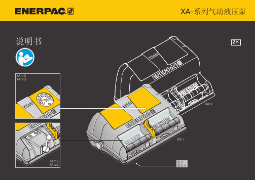
XA 设备使用说明书
ENERPAC XA 系列气动液压泵 使用手册说明书
不得将安全阀的压力值设置为超过泵的最大额定压力。
若安全阀压力值设置过高,则可能造成设备损坏或人身伤害。
不得拆除安全阀。
为避免人身伤害,操作过程中应使手、脚远离油缸和工件。
不得操作施压状态下的软管。
受压状态下,油管喷出的油能穿透皮肤,造成严重人身伤害。
如果油注入皮肤,请立即就医。
“危险”标志仅用于您的动作或您缺乏某种动作将规定操作将导致严重伤害或者死亡的情况。
安全性 2安装 4固定 5使用 6操作 7解锁 8阀的操作 9拆卸 10维护 11最大压力设置 12技术规格 13故障检修 14目录2Safety重要验收须知仔细查看是否有任何部件在运输过程中受损。
因运输造成的损坏不在保修范围内。
若有任何因运输造成的损坏,请立即通知承运人。
对于维修和更换运输过程中受损坏的部件所产生的全部费用,应由承运人负责。
安全问题/安全第一仔细阅读有关说明性文字、危险警示、警告信息和注意事项的各章节。
遵守各项安全措施,以免在系统操作过程中发生人身伤害或财产损失。
对于因未按安全说明使用产品、未进行维护或产品和(或)系统误操作所造成的财产损失和人身伤害,Enerpac 不承担责任。
若有任何关于安全措施和安全操作的疑问,请与 Enerpac 联系。
如果您从未受过有关高压液压安全的培训,请咨询经销商或服务中心,获取有关 Enerpac 液压安全课程的信息。
危险3未遵照以上或后面的危险警示、警告信息和注意事项的各章节进行操作可能会造成设备损坏和人身伤害。
应立即用正品 ENERPAC 部件更换磨损或损坏的部件。
非正品 Enerpac 部件可能会造成人身伤害和财产损失。
只有 ENERPAC 部件才能与设备完全搭配并且可以承受高负载。
知悉液压系统支持的负载。
一旦将油缸作为负载顶升设备,就不能再将其作为负载支撑设备。
在重物被顶升或下降以后,必须使用固定的机械支撑。
液压油缸必须在连接好的系统中使用。
油缸不得搭配不相连的接头。
如果油缸严重超载,则部件会出现重大故障,从而造成严重的人身伤害。
Axelwave AX9800 11g AP 11a BG无线设备管理用户手册
艾克赛尔(Axelwave)AX9800无线设备管理用户手册V 2.0二OO八年八月FCC(美国联邦通信委员会)声明本设备已经通过FCC各项有关的测试,根据FCC规定第15章,符号A类数字设备的限制,这些限制确保在安装使用时可以提供对有害干扰的防护。
本设备产生、使用并辐射射频能量,如果安装和使用不当,有可能会对无线电通信产生有害干扰。
该设备在社区(或生活区)环境中使用时,可能会产生有害干扰。
在这种情况下,用户要自行纠正干扰,使通信正常。
出于安全原因,人们应当工作在RF射频能量规定的标准范围以外。
为了防止这种情况发生,无线安装人员必须明确下列规则:天线安装位置要距离设备最少20厘米;安装天线时,要关闭无线设备的电源;当无线网络设备工作时,不要靠近天线。
版权版权所有得以保护,该手册的任何部分不得在生产,储存,保存与检索系统,翻译成其它任何语言,或以表单形式传送。
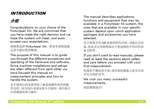
关于该手册本手册包括设备配置过程及方法,协助客户解决不可预见的问题。
目录1 说明 (4)2 硬件安装 (5)2.1 安装固定设备 (5)2.2 给设备供电 (5)2.3 硬件复位 (8)2.4 防水处理 (8)3 系统安装 (9)4 程序运行 (12)5 自动搜索 (13)6 配置管理 (16)7 设置设备的IP 地址 (18)7.1 手动设置IP地址 (19)7.2 自动获取IP地址 (20)8 配置5G网桥 (21)9 网桥安全设置 (27)9.1 Master Bridge 安全设置 (27)9.2 Share Key / Unique Key (29)9.2.1 设置 Share Key (29)9.2.2 设置 Unique Key (30)9.3 Slave Bridge 安全设置 (30)10 配置2.4G AP (32)11 AP安全设置 (35)11.1 WEP Security (36)11.2 WPA/WPA2 -PSK设置 (37)11.3 WPA/WPA2 -EAP设置 (39)12 NAT/DHCP 服务器配置 (40)12.1 NAT 配置 (40)12.2 DHCP 服务器配置 (42)12.3 PPPoE (PPP over Ethernet) (43)13 VLAN & Multiple SSID 配置 (43)14 网络状态 (45)14.1 Bridge 连接状态 (45)14.2 AP连接状态 (46)附录 A: 名词缩写 (48)1 说明感谢您选用艾克赛尔(Axelwave)无线网络产品。
xa使用中文说明
Measurement results
测量结果
测量结果同时显示水平竖直方向的对中值与调整值。左侧的符号表示位移偏差与角度偏差,以及是否在公差范围内。
Within tolerance (green).
绿色表示在公差允许内
Within double tolerance (yellow and inverted).
设置测量方法及其它
SETTINGS设置
此设定为本应用的唯一设定。所设功能取决于选择的应用套装与附件。
Measurement unit and resolution shown测量单位与精度
Opens window for selection of measurement unit and resolution shown.
Screen lock锁屏
Locks the screen.
Resume function重新开始
Stores system data to allow a resume to be performed after OFF.
Global settings总设置
Opens Global settings. See chapter “Global settings”.
环境设定
Batteryindicator
电池电量显示
Wireless indicator
Lit when wireless communication is activated.无线蓝牙显示
Backlight
背光调整
Off
关机
OFF options关机选项
按下关机按钮后,弹出对话框会让您选择关机,睡眠还是返回
如果您不像阅读手册,请在您的测量之前至少阅读安全保护章节。
MOXA NPort 5200系列串口设备联网服务器 说明书
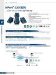
> NPort® 5200系列标准TCP/IP接口和多样的操作模式为现存的软件提供Real COM/TTY驱动通过TCP/IP或COM/TTY端口远程控制串口设备NPort® 5200系列串口设备联网服务器提供了TCP Server、TCP Client和UDP Server Client模式,使用了统一标准的网由于NPort®提供Real COM/TTY驱动功能,软件设计者透过COM/TTY的串口可以立即与TCP/IP网络进行连接。
这个卓越设备通过指定NPort® 5200的IP地址和端口号,服务器可以直接透过Scoket程序对串口设备进行数据读取和控制。
在Windows/Linux下基于COM/TTY的程序可以通过Moxa提供络API (Winsock,BSO Sockets)来确保网络软件的兼容性。
的特征能保障您的软件投资并且享受串口设备联网带来的好处。
的COM/TTY驱动,通过网络直接对串口设备的资料进行读取。
COM驱动/网络Sockets模式远程主机(Windows或Linux)Ethernet192.168.10.2:4001NPort® 5230/5232最多32个串口2线RS-485本地主机(Windows或Linux)Internet2-242-25 e-mail :china@ 免费技术热线:800-820-5036串口设备联网服务器 > NPort ® 5200系列2外观规格以太网端口数:1速率:10/100 Mbps ,自适应MDI/MDIX 接头:8针RJ45电磁隔离保护:内建1.5 KV 串口端口数:2串口标准:NPort ® 5210:RS-232NPort ®5230:1个RS-232,1个RS-422/485NPort ®5232/5232I :RS-422/485端口类型:NPort ® 5210:RJ45 (8-pin)NPort ®5230/5232/5232I :接线端子 (5针/口)串口保护:全信号15 KV ESD 保护2 KV 光电隔离 (NPort ® 5232I/5232I-T)RS-485数据流向控制:ADDC ® (数据流向自动控制)串口通讯参数数据位:5,6,7,8停止位:1,1.5,2校验位:None ,Even ,Odd ,Space ,Mark 流量控制:RTS/CTS (仅RS-232),DTR/DSR (仅NPort 5210),XON/XOFF 波特率:110 bps ~ 230.4 Kbps 串口信号RS-232:NPort ® 5210:TxD ,RxD ,RTS ,CTS ,DTR ,DSR ,DCD ,GNDNPort ® 5230:TxD ,RxD ,RTS ,CTS ,GNDRS-422:Tx+,Tx-,Rx+,Rx-,GND RS-485-4w :Tx+,Tx-,Rx+,Rx-,GND RS-485-2w :Data+,Data-,GND 软件特点网络协议:ICMP ,IP ,TCP ,UDP ,DHCP ,BOOTP ,Telnet ,DNS ,SNMP V1/V2c ,HTTP ,SMTP ,SNTP配置方式:Web Console ,Serial Console (NPort ® 5210/5230 only),Telnet Console ,Windows UtilityWindows Real COM 驱动:Windows 95/98/ME/NT/2000,Windows XP/2003/Vista/2008/7 x86/x64,Embedded CE 5.0/6.0,XP EmbeddedFixed TTY驱动:SCO Unix ,SCO OpenServer ,UnixWare 7,UnixWare 2.1,SVR 4.2,QNX 4.25,QNX 6,Solaris 10,FreeBSD ,AIX 5.x ,HP-UX 11iLinux Real TTY 驱动:Linux kernel 2.4.x ,2.6.x 机械特性外壳:金属,IP30防护等级重量:NPort® 5210:340 gNPort ®5230/5232:360 g NPort ®5232I :380 g 尺寸:NPort ® 5210/5230/5232:无挂耳:67 x 100.4 x 22 mm (2.64 x 3.95 x 0.87 in)含挂耳:90 x 100.4 x 22 mm (3.54 x 3.95 x 0.87 in)NPort ®5232I:无挂耳:67 x 100.4 x 35 mm (2.64 x 3.95 x 1.37 in)含挂耳:90 x 100.4 x 35 mm (3.54 x 3.95 x 1.37 in)工作环境工作温度:标准型号:0 ~ 55 ˚C (32 ~ 131 ˚F)宽温型号:-40 ~ 75 ˚C (-40 ~ 167 ˚F)工作湿度:5 ~ 95% RH 存储温度:-40 ~ 85 ˚C (-40 ~ 185 ˚F)电源需求输入电压:12 ~ 48 VDC 电源功耗:NPort ® 5210:325 mA @ 12 V ,190 mA @ 24 V NPort ®5230:325 mA @ 12 V ,190 mA @ 24 VNPort ®5232:280 mA @ 12 V ,150 mA @ 24 VNPort ® 5230NPort ® 5210NPort ® 5232电源输入接线端子12 ~ 48 VDC以太网RJ45 10/100 Mbps重启按钮导轨安装工具(可选)RS-422/485RS-2328针RJ45,RS-232RS-422/485电源输入接线端子12 ~ 48 VDC电源输入接线端子 12 ~ 48 VDC以太网RJ45 10/100 Mbps重启按钮重置按钮以太网RJ45 10/100 MbpsDK-35A 导轨安装套件可选附件2-27 e-mail :china@ 免费技术热线:800-820-5036串口设备联网服务器 > NPort ® 5200系列2订购信息包装清单•NPort ® 5200系列串口设备联网服务器• 电源插座转3-pin 电源转接头• 软件光盘及文档• 快速安装指南 (打印版)•保修卡PIN RS-2321DSR (in)2RTS (out)3GND 4TxD (out)5RxD (in)6DCD (in)7CTS (in)8DTR (out)18针脚定义NPort ® 5210/5210-T (RS-232)8针RJ45接头NPort ® 5230/5230-TNPort ® 5232/5232I/5232-T/5232I-T (RS-232/422/485,端子连接器)(RS-422/485,端子连接器)可选型号NPort ®5210:2口RS-232串口设备联网服务器,0 ~ 55 ˚C 工作温度NPort ®5230:2口设备联网服务器,带1个RS-232口,1个RS-422/485口,0 ~ 55 ˚C 工作温度NPort ® 5232:2口RS-422/485串口设备联网服务器,0 ~ 55 ˚C 工作温度NPort ®5232I :2口RS-422/485串口设备联网服务器,带2 KV 光电隔离,0 ~ 55 ˚C 工作温度NPort ® 5210-T :2口RS-232串口设备联网服务器,-40 ~ 75 ˚C 工作温度NPort ®5230-T :2口串口设备联网服务器,1个RS-232口,1个RS-422/485口,-40 ~ 75 ˚C 工作温度NPort ® 5232-T :2口RS-422/485串口设备联网服务器,-40 ~ 75 ˚C 工作温度NPort ®5232I-T :2口RS-422/485串口设备联网服务器,带2 KV 光电隔离,-40 ~ 75 ˚C 工作温度可选配件(须单独购买)DK-35A :可选配件DIN-Rail 电源:详情见附件接线端子:详情见附件R xC T R T G N G N R x R x T x + /D a t a T x T x - / D a t a -R x G N R x T x + / D a t a T x - / D a t a -R x G N R x T x + / D a t a T x - / D a t a -。
梅思安说明书
Ultima-X系列气体探测器使用说明书(请以原版说明书为准)中美合资无锡梅思安安全设备有限公司WUXI MSA SAFETY EQUIPMENT CO. LTD.重要的警告本说明书只是对该类仪表作简要的介绍,具体使用说明请按原版英文说明书为准。
任何负责或将要负责安装、使用或维修本产品的人员都必须仔细阅读本说明书。
象任何复杂的设备一样,只有按照制造厂家的说明与要求去安装、使用及维修,才能使本仪表按设计的性能要求去年工作,否则,仪表将不能正常工作而致使依靠此仪表来保障安全的愿望无法实现,甚至发生更为严重的伤亡事故。
如果不按照本手册的说明去安装、使用及维修本仪表,无锡梅思安公司对本产品所作的保证将是无效的。
因此,请遵守本手册说明以保障你本人及员工的安全,欢迎用户在使用本产品之前写信或打电话来询问有关使用或维修方面的信息。
1注意事项1、本手册所叙述的变送器应按照产品标签、注意事项、警告等项说明(并仅限在指明的范围内)去安装、操作和维修保养。
2、为防止在危险环境下引燃起爆,当接通电源时探测器的防爆盒盖务必密闭。
如需打开盒盖维修或标定,先要确认环境空气中无可燃性气体存在,直至关上盒盖。
3、探测器设计用来检测空气中的可燃性气体、毒气、氧气或其蒸汽浓度,而不能测定水汽中或惰性气体中或严重缺氧环境中的可燃性气体与蒸汽浓度。
4、探测器探头探测器隔爆片上不能被粘污或涂漆。
如在安放探测器的场所进行喷漆,须注意确保探测器入口处的粉末冶金隔爆片上不能粘有漆,否则,漆会阻碍被监测的气体扩散进入探测器。
安装时探测器朝下并离地面至少0.3M,以方便检修及标定,要杜绝雨水的滴入和地面水的溅入。
5、确保探测器正常工作的唯一方法是用已知浓度的气体对探测器进行标定检查,因此标定检查应作为此系统日常检查工作的一部分。
6、探测器的电源电压为7~30VDC,推荐工作电压为24VDC。
超过30VDC的电压将导致仪表的永久性损坏!7、在进行本手册所介绍的操作和保养时,只可以使用真正无锡梅思安公司的配件,否则,可能会严重影响仪表性能。
广一XA卧式单级单吸离心泵选型样本手册

2
轴 Shaft 轴套 Shaft sleeve 密封环 Wearring
��������� ����� �� 用户可根据使用的需要选用泵过流部件的零件材料,在合同中说明 When ordering the goods, please indicate the materials to be userd for wet components according to their requirement
2900r/min Capacity(Max.) Hade (Max.) Speed(Max.) Temperature(Max.) Temperature(Min.) Operating Pressure(Max.) 100L/s 100m 3500r/min(Used under 60Hz) 1450r/min 150L/s 55m 3500r/min(Used under 60Hz)
SH-XJA 蓄电池在线监控系统使用说明书
保定市三辉电气有限公司BAODING SANHUI ELECTRIC CO.,LTD使用说明书SH-XJ A型蓄电池在线监控系统目录◇产品简介 (1)✧产品定义 (1)✧装置特点 (1)✧型号说明 (1)✧系统构成 (2)◇外观结构 (3)✧接线端子外观 (3)✧前面板外观 (3)◇操作说明 (3)✧后台软件配置 (3)✧液晶面板操作 (9)◇参数指标 (13)✧结构参数 (13)✧性能参数 (13)◇电压电流测量装置 (14)✧概述 (14)✧外形及接线 (15)✧软件使用说明 (16)◇注意事项 (20)◇服务指南 (20)1产品简介1.1产品定义蓄电池在线监控系统是由SH-XJA蓄电池在线监控装置(也称集中器)、SH-M100电压电流测量装置及SH-RMO蓄电池内阻监测模块三部分组成。
其中,蓄电池在线监测装置是蓄电池直流系统中的在线监控产品,它采用新一代ARM处理器,具有采集蓄电池电压、温度、内阻、充放电状态等参数的功能,可通过网络把采集到的参数上传到服务器。
并且能管理开入装置、开出装置、放电装置、充电机与绝缘监察装置。
1.2装置特点☆采用Cortex-M3内核处理器,搭配μcos-II操作系统,运算性能更加强劲,数据监测更加实时。
☆选用液晶中文显示,界面简单直观,操作方便。
☆采用标准Modbus协议,方便与其它设备互联。
☆具有Nand Flash芯片,在服务器断开条件下可为每串蓄电池存储2000条历史数据。
☆系统设计“看门狗”电路,无论出现何种异常导致设备失灵,系统均可自动恢复。
1.3型号说明SH-XJ(A)内阻测试蓄电池在线监控装置保定市三辉电气有限公司1.4系统构成……霍尔传感器…SH-XJA 蓄电池在线监控装置(集中器)蓄电池1蓄电池2蓄电池n内阻监测模块1内阻监测模块2内阻监测模块nWeb 服务器远程客户端1远程客户端2远程客户端n……局域网电压电流测量装置2外观结构2.1接线端子外观2.2前面板外观①信号指示灯②显示屏幕③键盘④上电开关3操作说明3.1后台软件配置对一组或两组蓄电池组(不超过108块)建议用一台集中器配备与蓄电池相应数量的蓄电池内阻监测模块来实现在线监测功能和装有蓄电池在线监测软件的Linux主机组成蓄电池在线监测系统,即可完成对所有蓄电池的在线监测。
ABB Industrial 800xA 系统 AC 800M 控制与I_O产品说明书
6
3BSE034989R0121
IndustrialIT 800xA 系统
以完善的维护功能,缩短停运时间
800xA 控制器和 I/O 采用了一整套完善的自我诊断功能,有助于降低维护成 本。 所有模块都配备了前面板 LED 显示器,显示故障和性能降低情况。 各模块可采用报警与事件消息的方式,向操作和维护人员进行错误报告,并 由系统通过电子邮件和 (或)短消息将错误报告转发到工厂的关键人员。有 关报告这种特色功能的说明,请参阅 《800xA 操作概述》一文。 800xA 控制和 I/O 可与 800xA 特有的 " 资产优化 " 功能全面集成,从而以电 子的方式将故障报告提交到相关的维护管理系统 (这些报告将作为工作单的 基础),这样就实现了维护过程的流线化。有关 800xA" 计算机化管理系统 (CMMS)" 集成功能的进一步说明,请参阅 《800xA 资产优化概述》一文。 各模块可带电更换,并通过键控确保更换过程中模块类型的正确无误。
3BSE034989R0121
5
AC 800M 控制与 I/O
通过集成,实现即插即产的连通性
800xA 控制器和 I/O,将传统上孤立的工厂设备、系统无缝地集成到 800xA 系统环境,从而将自动化系统延伸到工厂的所有领域。这样就得到了工厂更 为简单的软件表达,既可以有简单的分断式开关和阀门,还可以有智能化现 场设备、专用控制子系统、变速动力装置、智能化 INSUM 开关柜以及流行的 PC 监控系统。
- 以公有环境,同时监控工厂自动化和安 全设施: 高完整性控制器可在同一个 控制器中结合安全回路和控制程序, 从而促进过程设备的充分运用。
- 以容错性,最大限度提高工厂可用 性:健壮的设计、分布式的功能以及 高度灵活的冗余选项,为生产力、成 品率和资产回报提供了切实的保障。
奥林巴斯XA相机说明书
INSTRUCTIONSDESCRIPTION OF CONTROLS Rangefinder WindowExposure CounterFilm Winder Self-Timer/Battery Check LampStrap EyeletAperture LeverDistanceScale WindowLens Shutter ReleaseSelf-Timer/Battery Check BeeperNon-Slip Finger GripRewind CrankRewind Knob/Camera Back ReleaseDustBarrierViewfinderCdS Light SensorASA Film Speed LeverFocusing LeverX-Synchro ContactsFlash RetainingSocketFlashGuide Pin Hole(Side View)1Film Rewind Shaft Film ChamberSprocket Film Take-Up SpoolASA Film Speed WindowFilm SpeedAdjustment LeverAutoFlash SensorBattery ChamberTripod SocketRewind Release ButtonControl LeverCamera BackFlashClamping ScrewFilm Pressure PlateFlashDiffuser Window Flashtube Charge Lamp2TABLE OF CONTENTSThe Olympus XA is an aper-ture priority auto-exposurerangefinder camera setting newstandards for function and feel,appearance and performance.Please read the following pagescarefully and your new camerawill provide maximum per-formance and satisfaction.DESCRIPTION OF CONTROLS.............. Page 1•2PREPARATIONInstalling the Batteries.....................4Loading the Film....................... 5•6SIMPLE STEPS FOR TAKING PICTURESSetting the Aperture (7)Focusing (8)Releasing the Shutter (9)Unloading the Film (10)Self-Timer............................10Automatic Flash Photography.............. 11•12PHOTOGRAPHIC TECHNIQUESAperture and Depth of Field............... 13•14Shutter-Speed Priority Photography........... 15-16Backlighting Compensation..................17Daylight Synchronization (18)HELPFUL HINTS (19)CARE AND STORAGE (20)MAIN SPECIFICATIONS .......................... 21•22 3If the beeper doesn't signal, the batteries are inserted incorrectlyor are exhausted.The batteries will last about one year and must be replaced with two 1.5V silver oxide batteries(SR 44, EPX-76 or equivalent).Do not press the shutter release during battery check operation,or the battery will run down quickly, leaving the shutter open-ed. Return the lever to the normal position.2. Check the batteries.Set the control lever to "CHECK".The beeper emits a tone and the check lamp glows brightly.Installing the BatteriesPREPARATION1. Insert the batteries correctly.SR 44(EPX-76,MS-76 orequivalent)4Loading the Film1. Open the camera back and in-sert the film cartridge. (Dust Bar-rier is in closed position.)Never load the film in direct sun-light.2. Attach the film end to thetake-up spool.The film end must not stick outof the slot excessively.3. Start winding the film and closethe camera back.Film perforations must engagewith sprocket teeth and the filmmust be drawn flat.54. Open the Dust Barrier.If the Dust Barrier is not fully opened, the shutter cannot be released.5. Wind and expose two blankshots until the exposure countershows "1".The lens should be aimed towarda bright light when shooting.6. Set the ASA film speed.6SIMPLE STEPS FOR TAKING PICTURESSetting the Aperture1. Open the Dust Barrier and set the aperture lever ( mark) to the F-number required.2. Confirm the shutter speed in the viewfinder, aiming at the sub-ject.(The arrows indicate parallax cor-rection marks.)If the shutter speed nee-dle enters the striped, over-exposure warning zone,push the aperture lever downward so that the nee-dle points to "500" (1/500 sec) or under.If the needle points to"30" (1/30 sec) or under,be careful not to shake thecamera.(To make full use of aperture con-trol, see pages 13 & 14.)Aperture guideline (ASA 100)7Focusing3. Looking through the view-finder, compose and focus.If the subject distance is 0.85 ~1 meter (2.8 ~ 3.3 feet), framethe subject in the area under the2 parallax correction marks.Turn the focusing lever until the double image in the central rec-tangle fuses into one. Focusing can also be done with the knurled mount (e.g. when a tripod is in use).Out of focus In focus8Releasing the Shutterfuser window or auto flash sensor.4. Hold the camera steady andlightly press the shutter release.The release requires a minimum offinger pressure, reducing chance ofimage blur due to camera shake.9Unloading the Film Self-Timer5. When the film ends, rewind and remove it.Close the Dust Barrier, depress the rewind release button and rewind the film. When the crank turns freely, open the camera back and remove the film in the shade.Set the control lever to "SELF TIMER" and release the shutter.The beeper emits a tone and the check lamp glows intermittently.The shutter will release after a delay of about 12 sec. The lever also serves as a camera support.To stop the timer midway, return the lever to its normal position.10Automatic Flash Photography (Only the Electronic Flash A11 can be used.)2. Connect the flash unit to the camera.Insert the guide pin into the guide pin hole and turn the clampingscrew clockwise.After connecting, do not twistthe A11.1.5V AA battery(Alkaline preferred)1. Set the ASA film speed.If the ASA speed of the film to be used is close to "100" or "400",use the nearest setting. (ASA 80or 125 "100").113. Set the aperture lever to"Flash".The charge lamp pops up and theA11turns on automatically.The flash setting has been design-ed to require a stronger pressurethan the aperture setting.4. When the charge lamp glows,you are ready to fire.Do not move the lever once ithas been set for auto flash, or in-correct flash exposure may result.5. At the end of flashphotography, fully depress the charge lamp to turn the flash unit off.Maximum workingdistance 2.5m (8.2ft.) at ASA 100, 5m (16.4 ft.) at ASA 400.12PHOTOGRAPHIC TECHNIQUESAperture and Depth of FieldDepth of field is the area of accept-able sharpness in front of and be-hind the subject in focus. The larg-er the F-number used (from F2.8to F22), the deeper the depth of field. On the contrary, the smaller the F-number (from F22 to F2.8),the shallower this zone of accept-able sharpness.The table on the opposite page shows that when the camera-to-subject distance is 1m, the depthof field at F4 ranges from 0.91mto 1.12m.Making use of "out of focus" background or foreground effectsDeep-focus effects13(Camera-to-subject distances with are indicated on the camera's distance scale.)Depth of field tableCircle of least confusion 1/30 mm.Depth of field table Circle of least confusion 1/760 in.(in meters)(in feet)14To emphasize motion To stop movementShutter-Speed Priority PhotographyWhen photographing fast movingsubjects, the impression of move-ment can be emphasized by inten-tionally allowing the image to be blurred using a stow shutter speed.On the contrary, the movement can be "frozen" using a fast shut-ter speed.15Move the aperture lever until the needle points to the shutter speedrequired.If the shutter speed needle en-ters the striped zone, push the aperture lever downward so that the needle points to "500" or un-der.An aperture-priority auto-expo-sure camera, the XA lets you select the aperture freely, then automati-cally sets the right shutter speed for correct exposure. The shutter scale is visible in the viewfinder, so you can pick exactly the speed and aperture you like.If the needle points to "30" or under, hold the camera steady or support with a tripod; or use a faster shutter speed by pushing the lever upward; or use autoflash.16Compensated +1.5EVWhen shooting against the light(bright sky, beach, snow, or facing a window), the face tends to ap-pear dark on the image. In this case, use the control lever to pro-perly expose the most important area.Turn the lever to "BACK LIGHT+1.5" and release the shutter.You can get the same effect by reducing the ASA film speed set-ting.Back Lighting CompensationBefore compensation17In situations like these, compen-sate for the back lighting by using the control lever.Manual flash method is recom-mended for daylight fill-in. Setthe A11 film speed lever to "FULL" and the aperture lever tothe F-number (after having set tothe flash symbol) obtained fromthe guide number formula.Daylight Synchronization18HELPFULHINTSDust BarrierOpening the Dust Barrier fully switches the power ON, and all camera functions are ready to shoot. Closing the Dust Barrier switches the power OFF, and all camera functions arelocked.Foolproof electronic circuitWith the Dust Barrier closed and camera func-tions locked, the foolproof electronic circuit nonetheless allows the camera back to be opened for film loading, unlocking all relat-ed functions.Electronic feather-touch shutter release The release (pressure conductive polymer)responds to very light pressure. Pressing with a stroke as you normally do with other cam-eras is not needed.Treat the camera with care!Do not exert stronger pressure on moving parts than needed (Dust Barrier, levers,knobs). When attaching a tripod, care should be taken not to tighten the screw excessivelyand not to rotate the camera on the screw.Filters cannot be used with the XA.19CARE AND STORAGEAt the completion of photography, com-pletely close the Dust Barrier to prevent bat-tery drain and dust.Do not drop or hit the camera. Cameras that have been submerged in water are gen-erally irreparable.Do not touch the lens, viewfinder and range-finder window. If touched, wipe the surfacelightly with a clean, soft cotton cloth. Fin-gerprints, if not wiped off immediately, willeventually be unremovable.Never leave the camera near radios, TV sets,or magnets.Store the camera in a dry, well-ventilatedplace.Never store the camera where temperatures exceed 50°C (122°F) or below -20°C (-4°F). When you use the camera in temperaturesunder -10°C (14°F), it may sometimes fail to operate properly. To avoid this, warm thecamera before use.Have all repairs performed by an authorized OLYMPUS Service Center. You may send it directly or through the store where yourcamera was purchased.20MAIN SPECIFICATIONS (OLYMPUS XA)Camera type: 35mm rangefinder electronic lens-shut-ter camera.Film format: 35mm standard cassette (24 x 36mm). Lens: F. Zuiko 35mm F2.8, 6 elements in 5 groups. Shutter:Electronic between-lens shutter. Viewfinder: Bright frame finder, 0.55x.Shutter speed readout and over-exposure warning zone visible in finder.Focusing: Double-image coupled rangefinder, 0.85m(2.8 ft.) ~ infinity.Exposure control: Aperture-priority automatic ex-posure. Automatic shutter speed range 10 sec. to 1/500 sec. Backlighting compensation + 1.5EV. Film speed range: ASA 25 ~ 800.Aperture range: F2.8 ~ F22.Film advance: Rear winding thumbwheel.Exposure counter: Progressive type with automatic reset.Film rewind:Crank type with rewind release button.Shutter release: Electromagnetic feather touch shutter release.Self-timer: Electronic self-timer with 12 second delay.Blinking LED and electronic beeper (Piezoelectric Ceramic Vibrator) during self-timer operation. Flash mounting: Exclusive automatic Electronic Flash A11 attaches to (or detaches from) the cam-era in seconds.Setting camera's aperture lever to flash symbol switches the A11 on, and sets the XA for autoflash. Lens/finder cover: Sliding Dust Barrier. When opened, power is switched on and shutter release unlocks.When closed, power is switched off and shutter release locks.Power source: Two 1.5V silver oxide batteries SR 44 (Eveready EPX-76 or equivalent). Dimensions:102 (W) x 64.5 (H) x 40 (D) mm (4" x2.54" x 1.6").Weight: 225 grams or 7.9 oz. (less batteries).21MAIN SPECIFICATIONS (ELECTRONIC FLASH A11)Unit type: Automatic electronic flash unit exclusively for use with Olympus XA and XA2.Guide number: 10 (ASA 100, meters) or 33 (ASA 100, feet).Applicable ASA film speeds: ASA 100 and 400. Flash modes:Normal auto (XA, XA2) and manual mode (XA only) with switch lever.F stop for auto flash: F4Angle of coverage:Picture area of 35mm focal-length lens. (XA and XA2 utilize 35mm Zuiko lens.) Number of flashes: Approx. 150 with AA 'penlight' alkaline battery.Recycling time:Approx. 7 sec with AA alkaline bat-tery.Max. working distance: 2.5m (8.2 ft.) at ASA 100, 5m (16.4 ft.) at ASA 400.Connection to camera:Fitted onto left-hand edge of XA (XA2).Power switch: The flash unit is activated by setting camera's lever to flash symbol, popping up thecharge lamp and initiating electrical charge. Theflash unit turns off when the charge lamp ispressed down.Power source: One 1.5V AA 'penlight' battery (in-cluding Ni-Cd battery).Dimensions: 60 (H) x 36 (W)* x 33 (D) mm (2.4" x1.4" x 1.3").* Measured from interface.Weight: 65 grams or 2.3 oz. (less battery).22OLYMPUS OPTICAL CO., L TDOLYMPUS CAMERA CORPORATIONOLYMPUS OPTICAL CO. (EUROPA) GMBHOLYMPUS OPTICAL CO. (U.K.) LTD.Printed in Japan IELEE22 © 0382·37MS2-8 Honduras Street, London EC1Y OT X , United Kingdom. Tel. 0171-253-2772。
UCM630xA 系列企业级 IP PBX 远程办公业务手册说明书
UCM630xA系列企业级IP PBX远程办公业务手册目录功能概述 (1)套餐规格 (2)预置条件 (3)UCM上配置远程办公套件 (4)购买/应用服务 (4)SIP分机同步 (5)媒体NAT穿透服务 (6)使用外网远程通话服务 (7)使用桌面客户端GS Wave (7)匿名入会 (7)帐号登录GS Wave (8)使用手机客户端Wave app (9)匿名入会 (10)帐号登录Wave App (11)UCM上云备份 (12)手动备份 (12)定期备份 (13)还原 (13)UCM上的CDR(拨打详情报告) (14)远程通话CDR (14)远程通话统计表 (15)UCM上的用户并发统计表 (16)UCM上设置GDMS的对等中继 (17)GDMS上远程管理UCM设备 (20)添加UCM设备 (20)查看已绑定的UCM设备 (21)定制外网远程访问域名 (21)远程访问UCM WebUI页面 (23)重启UCM设备 (24)升级UCM设备的固件 (25)云存储&管理备份文件 (27)查看统计报表 (27)日报 (27)查看最近一个月的统计报表 (28)设置日报的接收邮箱 (30)查看套餐和UCM云存储空间使用情况 (31)GDMS上告警管理 (33)消息通知设置 (33)邮件通知设置 (34)SMS通知设置 (36)查看告警通知 (38)设备诊断 (40)开始诊断 (40)远程恢复配置文件 (42)Cloud IM服务 (43)图目录图表1:UCM远程办公套件初始界面 (3)图表2:GDMS PBX设备管理初始界面 (3)图表3:UCM630xA远程办公套件初始介绍界面 (4)图表4:UCM远程办公套件套餐生效界面 (4)图表5:UCM远程办公套件-SIP分机同步设置界面 (5)图表6:GDMS同步UCM SIP帐号界面 (6)图表7:UCM远程办公套件-媒体NAT穿透服务设置界面 (6)图表8:UCM远程办公套件-查看UCM外网地址界面 (7)图表9:GS Wave匿名入会界面 (8)图表10:UCM服务器登录界面 (8)图表11:UCM GS Wave登录界面 (9)图表12:UCM GS Wave使用界面 (9)图表13:Wave App首页 (10)图表14:Wave App匿名加会界面 (10)图表15:Wave App登录界面 (11)图表16:备份/还原界面 (12)图表17:新建备份界面 (12)图表18:定期备份配置界面 (13)图表19:还原配置界面 (13)图表20:CDR界面 (14)图表21:CDR过滤远程通话界面 (14)图表22:CDR统计表 (15)图表23:并发统计表 (16)图表24:VoIP中继设置 (17)图表26:VoIP中继->高级设置 (19)图表27:GDMS添加UCM设备界面 (20)图表28:GDMS查看UCM设备界面 (21)图表29:GDMS自定义UCM公网域名 (22)图表30:GDMS的定制UCM的远程服务地址界面 (22)图表31:GDMS的自定义域名设置界面 (22)图表32:GDMS的UCM列表 (23)图表33:UCM的登录页面 (23)图表34:UCM的主页 (24)图表35:GDMS的UCM列表界面 (24)图表36:GDMS的重启UCM设备界面 (25)图表37:GDMS的任务列表界面 (25)图表38:GDMS的UCM列表界面 (26)图表39:GDMS的升级固件界面 (26)图表40:GDMS的任务列表界面 (26)图表41:GDMS的UCM备份文件界面 (27)图表42:GDMS的UCM日报附件界面 (28)图表43:GDMS查看UCM设备的统计报表界面 (29)图表44:GDMS查看UCM设备的统计通话图表界面 (30)图表45:GDMS设置日报接收邮箱界面 (31)图表46:GDMS的UCM查看套餐和云存储空间界面 (31)图表47:GDMS的套餐过期邮件 (32)图表48:消息通知设置界面 (33)图表49:邮件通知设置界面 (35)图表51:告警通知界面 (38)图表52:设备诊断界面 (40)图表53:设备诊断详情信息界面 (40)图表54:还原备份文件界面 (42)图表55:套餐服务界面 (43)图表56:套餐申请界面 (44)图表57:套餐详情界面 (44)图表58:绑定UCM设备界面 (45)图表59:UCM Cloud IM服务管理界面 (45)功能概述感谢您购买潮流网络UCM6300A/UCM6302A/UCM6304A/UCM6308A IPPBX。
- 1、下载文档前请自行甄别文档内容的完整性,平台不提供额外的编辑、内容补充、找答案等附加服务。
- 2、"仅部分预览"的文档,不可在线预览部分如存在完整性等问题,可反馈申请退款(可完整预览的文档不适用该条件!)。
- 3、如文档侵犯您的权益,请联系客服反馈,我们会尽快为您处理(人工客服工作时间:9:00-18:30)。
地
址: 北京市顺义区林河开发区双河大街 16 号
邮政编码: 101300
销售处电话: 0086-10-58691108
0086-10-89451664
传
真: 0086-10-58690354
0086-10-89451779
外经处电话: 0086-10-58693398
易损件图 ..........................................................................................................63-69
3
XA5032 XA5032/2 XA5032/3
1 主要用途与适用范围
使用说明书
立式升降台铣床属于通用金属切削机床。 本机床的主轴锥孔可直接或通过附件安装各种圆柱铣刀、圆片铣刀、角度铣刀、 成型铣刀、端面铣刀等刀具,用以加工各种平面、斜面、沟槽、齿轮等。根据需要配 用不同的铣床附件,还可扩大本机床的使用范围。配用分度头,可铣切直齿齿轮和铰 刀等零件,分度由分度头来完成。如在配用分度头的同时,把分度头的传动轴与工作 台纵向丝杠用挂轮联系起来,尚可铣切螺旋面。本机床配用圆工作台,可以铣切凸轮 及弧形槽。 本机床的铣头可以进行顺时针或逆时针的调整,其调整范围为±45°。 本机床结构本身具有足够的刚性,能承受重负荷的切削工作,并能使用硬质合金 刀具进行高速切削,充分发挥刀具的效能。 综上所述,本机床使用范围非常广泛,适用于各行业各类机械加工部门。 本机床外形图见图 1。 本机床精度按 GB3933-83《升降台铣床 精度》
XA5032 XA5032/2 XA5032/3
立式升降台铣床
使用说明书
工作台面宽度 出厂编号
320 mm
中华人民共和国
北京第一机床厂
XA5032 XA5032/2 XA5032/3
使用说明书
欢迎您使用我厂的产品!
为了您和本产品的安全,请您在吊运、安装、使用、操作、保养、 维修本产品前,仔细阅读本使用说明书。
2
XA5032 /2 XA5032/3
使用说明书
图 13 主轴输出特性曲线图 ............................................................................................53 图 14 机床操纵位置 ........................................................................................................54 图 15 主轴轴承调整图 ....................................................................................................57 图 16 自锁器调整图 ........................................................................................................58 图 17 纵向丝杠轴向间隙调整图 ....................................................................................58 图 18 进给变速箱外观图 ................................................................................................59 图 19 进给箱电刷结构图 ................................................................................................60 图 20 工作台左视图 ........................................................................................................61 图 21 摇臂结构图 ............................................................................................................62
0086-10-58690247
传
真: 0086-10-58693594
E- Mail: BYJC@
1
XA5032 XA5032/2 XA5032/3
使用说明书
目录
1 主要用途与适用范围 ....................................................................................................... 4 2 工作安全注意事项 ........................................................................................................... 4 3 工作条件 ......................................................................................................................... 9 4 主要规格及技术参数 ..................................................................................................... 9 5 主要结构性能及机械传动系统 ................................................................................... 11 6 润滑系统 ....................................................................................................................... 21 7 冷却系统 ....................................................................................................................... 21 8 电气系统 ....................................................................................................................... 22 9 开箱、吊运、保管 ....................................................................................................... 26 10 安装与试车 ................................................................................................................. 26 11 使用与操作..................................................................................................................27 12 机构的调整 ................................................................................................................. 29 13 维修及常见故障排除 ................................................................................................. 30 14 附件及易损件 ............................................................................................................. 32 图 1 XA5032 立式升降台铣床外形图...........................................................................34 图 2 机械传动系统图 ......................................................................................................37 图 3 主传动电磁离合器制动结构图 ..............................................................................38 图 4 主轴转速分布图 ......................................................................................................39 图 5 进给箱电磁离合器结构图 ......................................................................................40 图 6 进给速度分布图 ......................................................................................................41 图 7 滚动轴承位置图 ......................................................................................................42 图 8 机床润滑图 ..............................................................................................................43 图 9 机床电气原理图 ......................................................................................................44 图 10 机床电气接线图 ....................................................................................................47 图 11 机床吊运图.............................................................................................................51 图 12 安装基础图 ............................................................................................................52