DH77X-10ZB1蝶式止回阀
蝶式止回阀-H76H蝶式止回阀
510
1140
570
1395
45
DN80
630
1320
675
1530
46
DN100
690
1530
750
1875
47
DN125
960
2250
1005
2475
48
DN150
1185
2760
1260
3075
49
DN200
1590
3780
1890
4650
50
DN250
2070
5355
2430
6270
12375
12225
82
DN1200
69660
169500
16635
16200
18120
83
DN1400
84780
256500
19575
21150
23250
84
DN1600
113400
361200
23280
24300
25800
D371X-10C
D71X-10Q
公称
通径DN
出厂价
(元)
公称
通径DN
出厂价
100920
17
DN900
26790
28080
33750
63000
104700
138870
18
DN1000
37260
39345
50490
81000
106920
182850
19
DN1200
55965
58995
74250
主风机更换蝶阀安全技术措施
主要通风机更换蝶阀实施方案及安全技术措施一、基本情况我矿在用2#主要通风机蝶形阀(型号:№3200)内部轴键槽损坏、阀门电动装置(ZB60-24/150(380))异常,导致蝶阀不能正常开启关闭,为确保主要通风机安全稳定运行,需对蝶形阀及阀门电动装置进行更换,为确保施工安全有序进行,特制定本实施方案及安全技术措施。
二、组织机构及职责为了合理安排人员,提高工作效率,尽量减少或避免相互影响,使各环节紧密衔接,确保工作安全有序进行,特成立领导小组。
(一)组织机构组长:(矿长)常务副组长:(总工程师)副组长:(通风副矿长)(生产副矿长)(安全副矿长)(机电副矿长)成员:(通风副总工程师)(机电副总工程师)(安全副总工程师)(通风科长)(安全科长)(井下机电队长)(机电科长)(地面机电队长)(通风队长)(安全监测监控中心主任)(安全调度指挥中心主任)(二)职责组长:全面负责更换2#主要通风机蝶阀工作;常务副组长:协助组长统一指挥安排,做好更换主要通风机蝶阀过程中技术指导工作;副组长:协助组长做好更换主要通风机蝶阀过程中安全监管工作;安全调度指挥中心:负责施工过程中指令的上传、下达工作,以及所需人力、物力、车辆的协调工作;通风科:负责编制主要通风机更换蝶阀实施方案及安全技术措施,并组织相关人员贯彻学习;安全科:负责安全技术措施的监督落实和作业场所的警戒任务;通风队:负责更换主要通风机蝶阀的具体工作;地面机电队:协助通风队做好更换主要通风机蝶阀工作。
三、风险辨识及管控措施(一)风险分析:采用起重机吊装蝶阀,作业人员不清楚现场危险源或现场监护不力,人员盲目作业,可能发生高空坠物伤人事故。
管控措施:施工前必须组织人员进行贯彻学习,施工时指派专职安全员现场监护,严格按照施工方案及措施执行。
(二)风险分析:作业过程中,参与人员不佩戴劳动防护用品而进行作业,可能发生坠物伤人事故。
管控措施:作业全程必须按规定戴安全帽,穿防滑软底鞋,高空作业时必须佩戴安全带等防护用品。
上海环巨阀门有限公司-H76H、H76Y、H76W、H76X、H76F 型对夹蝶形止回阀

H76H、H76Y、H76W、H76X、H76F 型对夹蝶形止回阀用于纯净管路及工业、环保、水处理、高层建筑给排水管路,阻止介质逆向流动之用。
【产品特点】1、体积小,重量轻,结构紧凑、维修方便2、阀板采用对偶式,在弹簧的弹性力下矩下可自行速闭3、因速闭作用,可防止介质倒流4、阀体结构长度尺寸小,刚性好5、安全方便,可用于水平垂直两个方向安装【执行标准】1、法兰连接尺寸:GB/T1724.1-982、结构长度:GB/T12221-1989,ISO5752-82【性能参数】型号工作压力(MPa)适用温度(℃)适用介质阀体材料H76H-10C~401.0~4.0-29~425水、蒸汽、油品碳钢H76W-10P~251.0~2.5≤150硝酸类不锈钢H76Y-40P 4.0≤150硝酸类不锈钢HH47、H47XF、HDH47X 蝶式缓冲止回阀主要外形和连接尺寸公称通径DN (mm)尺寸(mm)L H B1 B2200 230 550 540 600 250 250 630 600 700 300 270 690 650 740 350 290 780 710 800 400 310 860 770 870 450 330 910 830 920 500 350 980 900 1000公称通径DN (mm)尺寸(mm)L H B1 B2600 390 1070 1090 1250 700 430 1220 1200 1360 800 470 1320 1320 1480 900 510 1430 1420 1580 1000 550 1550 1550 1700 1200 630 1800 1780 1950 1400 710 1980 2000 2175【结构图片】。
闸阀价格表

备注
螺阀
D71X-10
DN50
中线对夹般阀,中体
蝶阀
D71X-10
DN65
中线对夹蛛阀,中体
螺阀
D71X-10
DN80
中线对夹螺阀,中体
蛛阀
D71X-10
DN100
中线对夹螺阀,中体
螺阀
D71X-10
DN125
中线对夹蟆阀,中体
螺阀
D71X-10
DN150
130
中线对夹般阀,中体
螺阀
D71X-10
DN50
144
普通暗杆法兰闸阀,
阀体铸铁.
恒通闸阀
Z45X-16
DN65
180
普通暗杆法兰闸阀,
阀体铸铁
恒通闸阀
Z45X-16
DN80
228
普通暗杆法兰闸阀,
阀体铸铁
恒通闸阀
Z45X-16
DN100
303
普通暗杆法兰闸阀,
阀体铸铁
恒通闸阀
Z45X-16
DN125
462
普通暗杆法兰闸阀,
阀体铸铁
恒通闸阀
DN65
270
普通暗杆法兰闸阀,阀体铸铁
标光闸阀
Z45X-16
DN80
普通暗杆法兰闸阀,阀体铸铁
标光闸阀
Z45X-16
DN100
普通賠杆法兰闸阀,阀体铸铁
标光闸阀
Z45X-16
DN125
581
普通暗杆法兰闸阀,阀体铸铁
标光闸阀
Z45X-16
DN150
普通暗杆法兰闸阀,阀体铸铁
福建标光阀门丝口闸阀
名称
DN300
735
多种止回阀规格大全
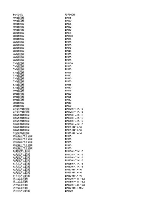
材料名称型号/规格401止回阀DN15401止回阀DN20401止回阀DN25401止回阀DN32401止回阀DN40401止回阀DN50403止回阀DN100403止回阀DN15403止回阀DN20403止回阀DN25403止回阀DN32403止回阀DN40403止回阀DN50403止回阀DN65403止回阀DN80530止回阀DN100530止回阀DN15530止回阀DN20530止回阀DN25530止回阀DN32530止回阀DN40530止回阀DN50530止回阀DN65530止回阀DN80603止回阀DN15603止回阀DN20603止回阀DN25603止回阀DN32603止回阀DN40603止回阀DN50C型消声止回阀DN100 H41X-16 C型消声止回阀DN125 H41X-16 C型消声止回阀DN150 H41X-16 C型消声止回阀DN200 H41X-16 C型消声止回阀DN250 H41X-16 C型消声止回阀DN300 H41X-16 C型消声止回阀DN50 H41X-16C型消声止回阀DN65 H41X-16C型消声止回阀DN80 H41X-16不锈钢丝口止回阀DN15不锈钢丝口止回阀DN20不锈钢丝口止回阀DN25不锈钢丝口止回阀DN40不锈钢丝口止回阀DN50对夹消声止回阀DN100 H71X-16对夹消声止回阀DN125 H71X-16对夹消声止回阀DN150 H71X-16对夹消声止回阀DN200 H71X-16对夹消声止回阀DN250 H71X-16对夹消声止回阀DN300 H71X-16对夹消声止回阀DN50 H71X-16对夹消声止回阀DN65 H71X-16对夹消声止回阀DN80 H71X-16法兰式止回阀DN100 H44T-16Q 法兰式止回阀DN150 H44T-16Q 法兰式止回阀DN200 H44T-16Q法兰消声止回阀DN125法兰消声止回阀DN150法兰消声止回阀DN200法兰消声止回阀DN250法兰消声止回阀DN300法兰消声止回阀DN50法兰消声止回阀DN65法兰消声止回阀DN80法兰止回阀DN100法兰止回阀DN100 H44T/W/X-10法兰止回阀DN125 H44T/W/X-10法兰止回阀DN150法兰止回阀DN150 H44T/W/X-10法兰止回阀DN200法兰止回阀DN200 H44T/W/X-10法兰止回阀DN250 H44T/W/X-10法兰止回阀DN300 H44T/W/X-10法兰止回阀DN350 H44T/W/X-10法兰止回阀DN40 H44T/W/X-10法兰止回阀DN400 H44T/W/X-10法兰止回阀DN50 H44T/W/X-10法兰止回阀DN500 H44T/W/X-10法兰止回阀DN600 H44T/W/X-10法兰止回阀DN65 H44T/W/X-10法兰止回阀DN80法兰止回阀DN80 H44T/W/X-10法兰止回阀H44T-16 DN100法兰止回阀H44T-16 DN150法兰止回阀H44T-16 DN200法兰止回阀H44T-16 DN50法兰止回阀H44T-16 DN65法兰止回阀H44T-16 DN80法兰止回阀Z44T-10 DN100法兰止回阀Z44T-10 DN1000法兰止回阀Z44T-10 DN125法兰止回阀Z44T-10 DN150法兰止回阀Z44T-10 DN200法兰止回阀Z44T-10 DN250法兰止回阀Z44T-10 DN300法兰止回阀Z44T-10 DN350法兰止回阀Z44T-10 DN40法兰止回阀Z44T-10 DN400法兰止回阀Z44T-10 DN450法兰止回阀Z44T-10 DN50法兰止回阀Z44T-10 DN500法兰止回阀Z44T-10 DN600法兰止回阀Z44T-10 DN65法兰止回阀Z44T-10 DN700法兰止回阀Z44T-10 DN80法兰止回阀Z44T-10 DN800法兰止回阀Z44T-10 DN900缓闭式止回阀300X DN100缓闭式止回阀300X DN125缓闭式止回阀300X DN150缓闭式止回阀300X DN200缓闭式止回阀300X DN250缓闭式止回阀300X DN300缓闭式止回阀300X DN80缓闭式止回阀DN100 SGH300X-16缓闭式止回阀DN125 SGH300X-16缓闭式止回阀DN150 SGH300X-16缓闭式止回阀DN200 SGH300X-16缓闭式止回阀DN250 SGH300X-16缓闭式止回阀DN300 SGH300X-16缓闭式止回阀DN40 SGH300X-16缓闭式止回阀DN50 SGH300X-16缓闭式止回阀DN65 SGH300X-16缓闭式止回阀DN80 SGH300X-16黄铜卧式止回阀DN100 401黄铜卧式止回阀DN15 401黄铜卧式止回阀DN20 401黄铜卧式止回阀DN25 401黄铜卧式止回阀DN32 401黄铜卧式止回阀DN40 401黄铜卧式止回阀DN50 401黄铜卧式止回阀DN65 401黄铜卧式止回阀DN80 401升降式止回阀DN100 H41T/W/X-16升降式止回阀DN125 H41T/W/X-16升降式止回阀DN15 H41T/W/X-16升降式止回阀DN150 H41T/W/X-16升降式止回阀DN20 H41T/W/X-16升降式止回阀DN200 H41T/W/X-16升降式止回阀DN25 H41T/W/X-16升降式止回阀DN250 H41T/W/X-16升降式止回阀DN32 H41T/W/X-16升降式止回阀DN40 H41T/W/X-16升降式止回阀DN50 H41T/W/X-16升降式止回阀DN65 H41T/W/X-16升降式止回阀DN80 H41T/W/X-16丝口止回阀DN100丝口止回阀DN100丝口止回阀DN15丝口止回阀DN15丝口止回阀DN20丝口止回阀DN20丝口止回阀DN25丝口止回阀DN25丝口止回阀DN32丝口止回阀DN40丝口止回阀DN40丝口止回阀DN50丝口止回阀DN50丝口止回阀DN65丝口止回阀DN65丝口止回阀DN80丝口止回阀DN80丝口止回阀H414X/T-10 DN100丝口止回阀H414X/T-10 DN20丝口止回阀H414X/T-10 DN25丝口止回阀H414X/T-10 DN40丝口止回阀H414X/T-10 DN50丝口止回阀H414X/T-10 DN65丝口止回阀H414X/T-10 DN80橡胶板止回阀DN125 H44T-16Q 橡胶板止回阀DN125 H44X-16Q 橡胶板止回阀DN150 H44T-16Q 橡胶板止回阀DN150 H44X-16Q 橡胶板止回阀DN200 H44T-16Q 橡胶板止回阀DN200 H44X-16Q 橡胶板止回阀DN40 H44X-16Q橡胶板止回阀DN50 H44T-16Q橡胶板止回阀DN50 H44X-16Q橡胶板止回阀DN65 H44T-16Q橡胶板止回阀DN65 H44X-16Q橡胶板止回阀DN80 H44T-16Q橡胶板止回阀DN80 H44X-16Q橡胶板止回阀H44X-16 DN100橡胶板止回阀H44X-16 DN125橡胶板止回阀H44X-16 DN150橡胶板止回阀H44X-16 DN200橡胶板止回阀H44X-16 DN250橡胶板止回阀H44X-16 DN300橡胶板止回阀H44X-16 DN50橡胶板止回阀H44X-16 DN65橡胶板止回阀H44X-16 DN80旋启式止回阀DN100 H44T/W/X-16旋启式止回阀DN125 H44T/W/X-16旋启式止回阀DN150 H44T/W/X-16旋启式止回阀DN200 H44T/W/X-16旋启式止回阀DN250 H44T/W/X-16旋启式止回阀DN300 H44T/W/X-16旋启式止回阀DN350 H44T/W/X-16旋启式止回阀DN40 H44T/W/X-16旋启式止回阀DN50 H44T/W/X-16旋启式止回阀DN65 H44T/W/X-16旋启式止回阀DN80 H44T/W/X-16止回阀DN100 AM401止回阀DN15 AM401止回阀DN20 AM401止回阀DN25 AM401止回阀DN32 AM401止回阀DN40 AM401止回阀DN50 AM401止回阀DN65 AM401止回阀DN80 AM401铸钢法兰止回阀H44H-16C DN100铸钢法兰止回阀H44H-16C DN125铸钢法兰止回阀H44H-16C DN15铸钢法兰止回阀H44H-16C DN150铸钢法兰止回阀H44H-16C DN20铸钢法兰止回阀H44H-16C DN200铸钢法兰止回阀H44H-16C DN25铸钢法兰止回阀H44H-16C DN250铸钢法兰止回阀H44H-16C DN300铸钢法兰止回阀H44H-16C DN32铸钢法兰止回阀H44H-16C DN350铸钢法兰止回阀H44H-16C DN40铸钢法兰止回阀H44H-16C DN400铸钢法兰止回阀H44H-16C DN50铸钢法兰止回阀H44H-16C DN65铸钢法兰止回阀H44H-25C DN125铸钢法兰止回阀H44H-25C DN150铸钢法兰止回阀H44H-25C DN200铸钢法兰止回阀H44H-25C DN25铸钢法兰止回阀H44H-25C DN250铸钢法兰止回阀H44H-25C DN300铸钢法兰止回阀H44H-25C DN32铸钢法兰止回阀H44H-25C DN350铸钢法兰止回阀H44H-25C DN40铸钢法兰止回阀H44H-25C DN400铸钢法兰止回阀H44H-25C DN50铸钢法兰止回阀H44H-25C DN65铸钢法兰止回阀H44H-25C DN80铸钢法兰止回阀J41H-16C DN100铸钢法兰止回阀J41H-16C DN125铸钢法兰止回阀J41H-16C DN15铸钢法兰止回阀J41H-16C DN150铸钢法兰止回阀J41H-16C DN20铸钢法兰止回阀J41H-16C DN200铸钢法兰止回阀J41H-16C DN25铸钢法兰止回阀J41H-16C DN250铸钢法兰止回阀J41H-16C DN32铸钢法兰止回阀J41H-16C DN40铸钢法兰止回阀J41H-16C DN50铸钢法兰止回阀J41H-16C DN65铸钢法兰止回阀J41H-16C DN80铸钢升降式止回阀H41H-16C DN100铸钢升降式止回阀H41H-16C DN125铸钢升降式止回阀H41H-16C DN15铸钢升降式止回阀H41H-16C DN150铸钢升降式止回阀H41H-16C DN20铸钢升降式止回阀H41H-16C DN200铸钢升降式止回阀H41H-16C DN25铸钢升降式止回阀H41H-16C DN250铸钢升降式止回阀H41H-16C DN300铸钢升降式止回阀H41H-16C DN32铸钢升降式止回阀H41H-16C DN350铸钢升降式止回阀H41H-16C DN40铸钢升降式止回阀H41H-16C DN400铸钢升降式止回阀H41H-16C DN50铸钢升降式止回阀H41H-16C DN65铸钢升降式止回阀H41H-16C DN80个个个个个个个个个个个个个个个个个个个个个个个个个个个个个个个个个个个个个个个个个个个个个个个个个个个个个个个个个个个个个个个个个个个个个个个个个个个个个个个个个个个个个个个个个个个个个个个个个个个个个个个个个个个个个个个个个个个个个个个个个个个个个个个个个个个个个个个个个个个个个个个个个个个个个个个个个个个个个个个个个个个个个个个个个个个个个个个个个个个个个个个个个个个个个个个个个个个个个个个个个个个个个个个个个个个个个个个个个个个个个个个个个个个个个个个个个个个个个个个个个个个个个个个个个个个个个个个。
蝶式止回阀H76H
482
532
585
685
800
905
1005
1115
1325
H76
H
-
16
连接尺寸
25
W
40
通径DN
50
65
80
100
125
150
200
250
300
350
400
450
500
600
L
PN1.01.62.5
60
67
73
73
83
98
127
146
181
184
198
203
219
222
PN4.0
60
67
73
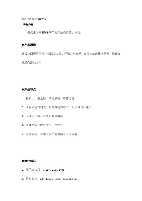
蝶式止回阀H76H/W/Y
详细介绍
蝶式止回阀H76H/W/Y的产品类型是止回阀.
◆产品用途
蝶式止回阀用于纯净管路及工业、环保、水处理、高层建筑给排水管路,阻止介质逆向流动之用
◆产品特点
1、体积小,重量轻,结构紧凑、维修方便
2、阀板采用对偶式,在弹簧的弹性力下矩下可自行速闭
3、因速闭作用,可防止介质倒流
73
83
98
127
146
181
222
231
/
/
/
D
PN1.0
107
127
142
162
192
218
273
328
378
438
489
539
594
695
PN1.6
107
127
142
162
192
218
273
阀门图片介绍
气、弱酸等
点击放大
手动固定球阀 型号: Q347F-16C/25/40/64C 公称通
径: DN50-DN800 公称压 PN1.6 、 PN2.5 、
力:PN4.0 、 PN6.4 适用温
≤ 150 ℃ 度: 适用介
水、油品、天然气 质:
点击放大
电动浮动球阀 型号: Q941F-16/25/40/64C/P/R 公称通
水、污水、油、弱酸 适用介质:
弱碱
点击放大
手动蝶阀 型号: D371X-10/16ZB 公称通径: DNห้องสมุดไป่ตู้0--DN1000 公称压力: PN1.0 PN1.6 适用温度: -35°C--135°C
水、污水、油、弱酸 适用介质:
弱碱
点击放大
电动蝶阀 型号: D971X-10/16ZB 公称通径: DN40--DN1000 公称压力: PN1.0 PN1.6 适用温度: -35°C--135°C
点击放大
对夹式蝶型止回阀 型号:H77X-10/16 公称通径:DN50—DN700 公称压力:PN1.0 、 PN1.6 适用温度:-15°C --150°C
蒸汽、污水、淡水、 适用介质:
油类、食品、药品
点击放大
法兰式消声止回阀 型号:H41X/T-10/16 公称通径:DN150-DN400 公称压力:PN1.0、PN1.6 适用温度:0°C --80°C
淡水、污水、海水、 适用介质:
空气
点击放大
点击放大
大口径单偏心法兰蝶阀
型号:D342X-2.5/6/10 公称通径:DN1400—DN2800
PN0.25 、 PN0.6 、 公称压力:
手动和自动耐久蝴蝶阀门安装和维护说明书
INSTALLATIONandCONTENTSIntroductionValve Description (3)Valve Design Features (3)Flange and Pipe Schedule Compatibility (3)Gasket Compatibility (3)Operating Pressures (3)Product Identification (3)Installation RecommendationsValve Ratings (4)Valve Seat Position (4)Disc Clearances (4)Opening Rotation (4)Installation Position (4)Valve and Flange Preparation (4)Installation Tools (4)Required Bolting (4)Unpacking and Storage Instructions (4)Pre-Installation Procedure (5)Valve Installation Procedure............................................................................................................5 & 6 Flange Bolting Recommendations (7)Maintenance InstructionsSafety Precautions (8)General Maintenance (8)Butterfly Valve Disassembly (8)Butterfly Valve Assembly.................................................................................................................8 & 9 Ratchet Handle Mounting Procedure.. (10)Manual Gear Mounting Procedure (10)Remote Actuator (Male Drive) Mounting Procedure (10)Remote Actuator (Female Drive) Mounting Procedure (10)Parts List (11)Stockham Figure Number System..........................................................................................Back Cover2T:800-STOCKHAM • F:256-775-3860 • Valve DescriptionThe Stockham Resilient Seat Butterfly Valve (RSBFV) is designed for use in ASME Class 150 piping systems and is available in both Wafer and Lug style body designs. The standard valve size range available is as follows:• 200 psi Standard BFV 2" to 12" 150 psi Standard BFV 14" to 36" • 285 psi BFV 2" to 24" Stockham 285 Butterfly Valve is also available with an ASME Class 300 bolt pattern for Lug bodies of sizes 2" through 12". Valve Design Features• The unique Stockham seat and disc design insures positive valve sealing while maintaining low seating torque. • All Stockham Butterfly Valve discs are precision machined to a half ball profile, providing a precise disc to seat relationship.• Stockham's cartridge style seat incorporates an elastomer bonded to a phenolic stabilizing ring, eliminating elastomer movement and reducing seat tearing or fatiguing due to bunching.• Stockham's basic three bushing design completely isolates the valve shaft from the body, resulting in increased control of the valve disc, lower valve seating torque, and longer valve life.• The Stockham cartridge seat has a much smaller massof elastomer than traditional boot seat designs, limiting seat swell and the accompaning variations in seating torque.Flange and Pipe Schedule CompatibilityThe Stockham RSBFV is designed to fit between standard piping flanges as follows:• ASME 125 Cast Iron Flanges (All Sizes)• ASME 150 Steel Flanges, Schedule 40 (All Sizes)• ASME150 Steel Flanges, Schedule 80 (2" to 10")• ASME 300 Steel Flanges, Schedule 40 (285 Lug,2" to 12" only).When using Schedule 80 piping, special care must be taken to make sure the valve is centered between the flanges to prevent damage to the disc edge when opening or closing. Gasket CompatibilityIn the Stockham butterfly valve design, the elastomerseat extends beyond the valve face and providesa leakproof seal between the valve and the mating pipe flange faces. Gaskets are not needed and should not be used when the valve is installed between standard weld neck or slip-on type flanges.Operating PressuresAll Stockham 200 Butterfly Valves are rated at 200psi bubble tight shut-off for sizes 2" to 12" and 150 psi bubble tight shut-off for sizes 14" and larger. Stockham 285 Butterfly Valves are rated for bubble tight shutoffat 285 psi.Product IdentificationEach Stockham valve has an identification tag attached to the valve body. Information on this tag includes the valve Series Number, materials of construction for the Body, Disc, and Seat, and the valve Pressure Rating.INTRODUCTIONSERIESBODYT:800-STOCKHAM • F:256-775-3860 • 31.2.3.4.5.6.7.8.Check the packing list against the valve received to verify that the size, material, and trim are correct.Check to make sure that the valve and operator were not damaged during shipment.When lifting the valve, take care to avoid damage to the flange faces, disc sealing edge, or operator.If the valve is to be stored before being installed, it should be protected from harsh environmental conditions.Store the valve with the disc in the “almost closed”position to protect the sealing edge and the seat.Keep the valve in a clean location, away from dirt, debris and corrosive materials.Keep the valve in a dry area with the flanges protected and on a suitable skid or pallet.Keep the valve in a cool location if possible, out of direct sunlight.Opening RotationThe Stockham valve disc can rotate 360° without damag ingthe valve or elastomer seat. The valve is designed toopen with either clockwise or counterclockwise rotation ofthe shaft.Valve RatingsStockham valves are intended for use at the pressure indicated on the nameplate attached to each individual valve. Check the valve operating temperature and pressure rating before proceeding with installation.4INSTALLATION RECOMMENDATIONSValve and Flange PreparationIf the valve and mating pipe are properly prepared for installation, future problems can be avoided. All valve seat and pipe flange faces should be free of dirt, grit, dents, or surface irregularities which may disrupt flange sealing and cause external leakage. The valve disc sealing surface should also be inspected to eliminate any dirt or foreign material that will adversely affect the operation of the valve.Installation PositionTo prevent damage to the disc and seat during installation,the valve disc should be slightly open but not extending beyond the valve liner face. Positioning the disc in this “almost closed” position will reduce seat interference and initial torque build-up during valve installation.In general, it is preferable to install RSBFV's with the shaftin a horizontal orientation. In this position, shaft and discweights are evenly distributed, minimizing seat wear.Additionally, any foreign matter which may accumulate atthe bottom of the disc and shaft is effectively removedeach time the valve is opened.Stockham butterfly valves are designed to operate be tweentwo flanges. If the valve installation calls for the use of onepipe flange only, a Lug style valve with Dead End Servicefeature must be used.Disc ClearancesPrior to installing the valve, it is important to make sure theID of the pipe and the pipe flanges are large enough to allow the disc edge to swing into the opening without interference.Damage to the disc edge can severly affect the performanceof the valve. Flange and pipe schedule compatibility forStockham valves is shown in Section 1 of this manual.All Stockham butterfly valves are completely bi-directional, so installation is not dependent on seat orientation. Bubble-tight shutoff will be achieved in this orientation with 25 to 150 psi ∆P across the valve.Unpacking and Storage InstructionsInstallation ToolsThe only tool required in the installation of a Stockham RSBFV is a wrench suitable for tightening the flange bolts and/or nuts required to secure the valve in-line. A hoist maybe required to help manipulate valves 10" and larger. Smaller sized valves can usually be installed by hand. Temporarypipe supports may be used to keep mating flange facesparallel in order to aid in valve installation.Required Bolting The table outlined on Page 7 is furnished to provide informa-tion regarding the size, type, and quantity of bolting recom-mended for the installation of Stockham RSBFV's. Thistable is intended for use as a planning and procurementguide. All recommendations are based on pipe flanges inaccordance with A SME 125/150 specifications. Flange bolt-ing is not included with the valve shipment.T:800-STOCKHAM • F:256-775-3860 • Valve Seat PositionINSTALLATION RECOMMENDATIONS5T:800-STOCKHAM • F:256-775-3860 • INSTALLATION RECOMMENDATIONS6Figure 4-Final Valve Alignment and Tightening of Flange BoltsT:800-STOCKHAM • F:256-775-3860 • 7Flange Bolting RecommendationsINSTALLATION RECOMMENDATIONS2"5/8-114 4.750 1.25015-602 1/2"5/8-114 5.250 1.50015-603"5/8-114 5.2501.50015-604"5/8-118 5.750 1.75015-605"3/4-108 6.000 1.75025-1006"3/4-108 6.2502.00025-1008"3/4-108 6.750 2.25025-10010"7/8-9127.250 2.25050-20012"7/8-9127.750 2.50050-20014"1-8128.250 2.75070-30016"1-8168.750 2.75070-30018"1 1/8-71610.0003.500 100-40020" 200 1 1/8-7 20 11.250 4.250 100-40020" 2851 1/8-7 1611.250 4.250 100-400+ 4 ea.5.000 3.250 100-40024" 200 1 1/4-72012.7504.750 150-50024" 285 1 1/4-71612.750 4.750 150-500+4 ea. 5.250 3.750 150-50030" 200 1 1/4-72413.750 4.500 150-500+4 ea.5.750 4.250 150-500Stockham Wafer And Lug Valves, 2"-30", A SME 125/150 Bolt PatternValve Thread Number Stud Length Bolt Length Req. TorqueSize Size RequiredWafer B'fly (in.)Lug B'fly (in.)(Ft-lbs)Bolting and torque recommendations are made without a warranty, and apply only to steel weld-neck or slip-on flanges.The use of lock washers and/or lubrication with the bolting will affect stated torque values.T:800-STOCKHAM • F:256-775-3860 • MAINTENANCE INSTRUCTIONSBe sure the line is depressurized and drained.Be sure of the pipeline media. Proper care should be taken for protection against toxic and/or flammable fluids.Never remove the valve without an Operator (Manual or Automatic) already attached to the valve shaft.Never remove the Operator from the valve while the valve is in the pipeline under pressure.Always be sure that the disc is in the closed position before removing the valve.1.2.3.4.5.Thoroughly clean all parts. Inspect components for anydefects.Apply a small amount of silicone grease to the insidesurfaces of the body, including the upper and lower shaft holes.Insert the shaft bushings into the body being careful not toallow intrusion into the body seat bore.Install the seat into the center of the body, making sure theshaft holes in the seat line up with the holes in the body.1.2.3.4.8Resilient SeatBushingsCompletely coat the inside surfaces of the seat withsilicone grease. Carefully push the disc into the seat in the open position (90 degrees to the body.) Line up the shaft holes of the disc as close as possible with the shaft holes in the seat body.5.Disc1.2.3.4.5.6.Position valve flat with the disc in the closed position.Loosen the taper pin(s) from the valve disc using a hammer and punch.Note: Punch should be of same size or larger diameter as small end of taper pin to avoid mush-rooming of taper pin.Remove taper pin(s) from disc. Extract the valve shaft from the body using a twisting motion.Remove the valve disc from body making sure not to damage the seat or disc sealing edge.Cartridge seat removal can be accomplished from ei-ther direction by applying pressure evenly on one face to push the seat through the body. If the valve is of dead end service design, remove set screws around periph-ery of body extending into seat prior to seat removal.Remove shaft bushings from body as required.General MaintenanceThe following periodic preventative maintenance practices are recommended for all Stockham Butterfly Valves.1.2.3.4.Operate the valve from full open to full closed to assure operability.Check flange bolting for evidence of loosening and correct as needed.Inspect the valve and surrounding area for previous or existing leakage at flange faces or shaft connections.Check piping and/or wiring to actuators and related equipment for looseness and correct as needed.Before removing the valve from the line or loosening any bolts, it is important to verify the following conditions:Butterfly Valve AssemblySafety PrecautionsButterfly Valve DisassemblyT:800-STOCKHAM • F:256-775-3860 • MAINTENANCE INSTRUCTIONS9T:800-STOCKHAM • F:256-775-3860 • Position the disc in the closed position.Install the actuator mounting bracket on the valve bodywith the actuator mounting holes facing up-ward. Fasten the bracket securely in place with the appropriate ma-chine bolts, nuts, and lock washers.Install the drive key in the keyway of the shaft. Tap the keyin place to insure it is fully seated.Install the drive coupling on the shaft by lining up theproper keyway in the coupling with the key in the shaft.Rotate the actuator shaft to the full clockwise position.Align the drive coupling with the actuator shaft and install the actuator on the mounting bracket.Fasten the actuator to the mounting bracket with theappropriate machine bolts and lock washers. It may be necessary to slightly rotate the actuator shaft to align the mounting holes in the actuator with the mounting bracket.Adjust the stops in the actuator to position the face of thedisc parallel with the face of the valve body in the closed position and perpendicular to the face of the valve body in the open position.Position the disc in the closed position.Install the drive key in the shaft. Tap the key into place to ensure it is fully seated.Rotate the gear shaft to the full clockwise position. Align the keyway in the gearbox bore with the key in the shaft and slide the gearbox onto the shaft.Fasten the gearbox to the mounting bracket with theappropriate machine bolts and lock washers. It may be necessary to rotate the gear shaft slightly to align the mounting holes in the gear with the plate.Adjust the stops in the gearbox to position the face of thedisc parallel with the face of the valve in the closed position and perpendicular to the face of the valve in the openposition.Ratchet Handle Mounting ProcedureMAINTENANCE INSTRUCTIONSPosition the disc in the closed position.Install the ratchet plate using machine bolts, nuts and lockwashers, but do not tighten the fasteners.Install the drive key in the shaft. Tap the key into place toensure it is fully seated in the keyway.Install the handle so that it is parallel with the disc face.The locking lever must be fully retracted before it will pass through the ratchet plate. Tighten the set screw in the handle against the key.With the handle installed flush with the ratchet plate,engage the locking lever with the ratchet plate. Using the handle, adjust the position of the ratchet plate until the disc face is parallel with the valve face, then tighten the fasteners securely.1.2.3.4.5.Remote Actuator (Male Drive)Mounting Procedure1.2.3.4.5.6.7.10Manual Gear Mounting Procedure1.2.3.Remote Actuator (Female Drive)Mounting Procedure 1.2.3.4.5.6.7.8.Position the disc in the closed position.Install the actuator mounting bracket on the valve bodywith the actuator mounting holes facing up. Fasten the bracket securely in place with the appropriate machine bolts, nuts, and lock washers.Install the drive key in the shaft. Tap the key in place to insure it is fully seated.Install the drive coupling on the shaft by lining up the proper coupling keyway with the key in the shaft.Install the drive key in the drive coupling. Tap the key in place to insure it is properly seated.Rotate the actuator to the full clockwise position. Align the keyway in the actuator bore with the key in the drive coupling and slide the actuator on the drive coupling.Fasten the actuator to the mounting bracket with the appropriate machine bolts and lock washers. It may be necessary to rotate the actuator slightly to align the actuator with the mounting bracket.Adjust the stops in the actuator to position the face of t he disc parallel with the face of the valve body in the closed position and perpendicular to the face of the valve body in the open position.T:800-STOCKHAM • F:256-775-3860 • 4.5.MAINTENANCE INSTRUCTIONST:800-STOCKHAM • F:256-775-3860 • 11Butterfly Valves** Please consult our factory for information concerning material recommendation for Viton.†285 CWP Products are available on request. Please contact Customer Service* Ductile disc is not recommended for water service.+/- Inquiries or orders must specify FDA requirementsMATERIALTYPERATINGTYPE。
管道与设备报价表
工程名称:华润九里一期站房工程
工程名称:华润九里一期站房工程
工程名称:华润九里一期站房工程
工程名称:华润九里一期站房工程
工程名称:华润九里一期站房工程
工程名称:华润九里一期站房工程
工程名称:华润九里一期站房工程
工程名称:华润九里一期站房工程
工程名称:华润九里一期站房工程
工程名称:华润九里一期站房工程
工程名称:华润九里一期站房工程
工程名称:华润九里一期站房工程
工程名称:华润九里一期站房工程
工程名称:华润九里一期站房工程
工程名称:华润九里一期站房工程
工程名称:华润九里一期站房工程
工程名称:华润九里一期站房工程
工程名称:华润九里一期站房工程
工程名称:华润九里一期站房工程
工程名称:华润九里一期站房工程
工程名称:华润九里一期站房工程
工程名称:华润九里一期站房工程
工程名称:华润九里一期站房工程
工程名称:华润九里一期站房工程
工程名称:华润九里一期站房工程
工程名称:华润九里一期站房工程
工程名称:华润九里一期站房工程。
对夹式蝶形止回阀标准__概述说明以及解释
对夹式蝶形止回阀标准概述说明以及解释1. 引言1.1 概述夹式蝶形止回阀是一种广泛应用于管路系统中的流体控制装置。
它具有简单结构、操作灵活并能有效地防止介质的倒流,因此在各个工业领域得到了广泛的应用。
本文将对夹式蝶形止回阀标准进行概述说明和解释。
1.2 文章结构本文共分为五个部分:引言、夹式蝶形止回阀标准概述、夹式蝶形止回阀标准说明、夹式蝶形止回阀解释相关问题以及结论。
下面将对每个部分的内容进行详细介绍。
1.3 目的本文旨在通过介绍夹式蝶形止回阀标准的概述和说明,加深读者对该标准的理解。
同时,针对该标准在产品选择、安装使用以及故障处理方面可能存在的问题,提供相应建议和解决方案。
最后,展望未来夹式蝶形止回阀标准发展趋势,并指出目前研究工作的局限性,提出未来研究方向建议。
以上就是本文章引言部分内容,请根据需要进行补充或修改。
2. 夹式蝶形止回阀标准概述:2.1 夹式蝶形止回阀定义:夹式蝶形止回阀是一种用于控制液体或气体流动方向的装置。
它由一个具有夹持机构的蝴蝶板和两个密封在管道内壁上的阀座组成。
当介质流向的方向与设定的流动方向一致时,夹式蝶形止回阀会自动打开,允许流体通过;而当介质反向流动时,夹式蝶形止回阀会自动关闭,避免倒流。
2.2 夹式蝶形止回阀的工作原理:夹式蝶形止回阀通过引入流体压力来驱动其开关机构。
当正常流动条件下,流体从过程管线中进入夹式蝶形止回阀,并顺着管道方向使弹簧处于压缩状态以保持开启状态,在这种情况下,媒介能沿着管道无阻碍地通过。
然而,如果发生逆向流动或系统压力降低到不足以克服弹簧力时,夹式蝶形止回阀将关闭以避免倒流。
2.3 夹式蝶形止回阀重要性及应用领域:夹式蝶形止回阀在工业管道和设备中扮演着重要的角色。
它能有效地防止逆向流动,在很大程度上降低了系统的能耗,减轻了操作过程中产生的冲击和振动,提高了系统的运行安全性。
因此,夹式蝶形止回阀被广泛应用于化工、电力、制药、石油、冶金等各个领域。
- 1、下载文档前请自行甄别文档内容的完整性,平台不提供额外的编辑、内容补充、找答案等附加服务。
- 2、"仅部分预览"的文档,不可在线预览部分如存在完整性等问题,可反馈申请退款(可完整预览的文档不适用该条件!)。
- 3、如文档侵犯您的权益,请联系客服反馈,我们会尽快为您处理(人工客服工作时间:9:00-18:30)。
DH77X-10ZB1蝶式止回阀
详细介绍
对夹式止回阀,止回阀安装在管路系统,其主要作用是防止介质倒流,止回阀是一种依靠介质压力开启和关闭的自动阀门。
品牌:KT
品名:蝶式止回阀DH77X-10ZB1
型号:DH77X-10ZB1
公称通径:DN40-DN700
公称压力:1.0-1.6MPa
适用温度:-15℃-80℃
适用介质:淡水、污水、海水、空气、蒸汽、食品、药品、各种油类、酸类、碱类、盐类等。
蝶式止回阀,DH77X-16,对夹式止回阀,止回阀安装在管路系统,其主要作用是防止介质倒流,止回阀是一种依靠介质压力开启和关闭的自动阀门。
以往国内普遍采用的是H44型法兰连接旋启式止回阀和H41型法兰连接升降式止回阀,这种传统的止回阀体积笨大,流体阻力大,阀门关闭时水锤压力高,安装、维修难,使用寿命短。
我公司针对传统结构止回阀存在的问题,以美国API标准和德国DIN标准为依据,结合我公司多年来在阀门试验研究、开发设计、加工制造等方面的丰富经验,研
制开发了H76型对夹双瓣旋启式止回阀和H71型对夹式升降式止回阀系列产品,经石化、冶金、电力、轻工、食品等行业的企业和设备配套厂家的多年使用,效果良好,深受用户好评。
1、结构长度短,其结构长度只有传统法兰止回阀的1/4~1/8;
2、体积小、重量轻,其重量只有传统法兰止回阀的1/4~1/20;
3、阀瓣关闭快速,水锤压力小;
4、水平管道或垂直管道均可使用,安装方便;
5、流道通畅、流体阻力小;
6、动作灵敏、密封性能好;
7、阀瓣行程短、关阀冲击力小;
8、整体结构、简单紧凑、造型美观;
9、使用寿命长、可靠性高;
10、达到完全密封,水压试验泄漏量为零;
11、实用性能安全可靠,抗干扰性好。
相关链接:/fmzhf/17371.shtml。