11_Frequency Response(频率响应)
emc 共模电感参数选取

EMC共模电感参数选取1. 简介电磁兼容性(Electromagnetic Compatibility,简称EMC)是指电子设备在特定的电磁环境中,能够以无干扰的方式正常工作,同时不对周围环境和其他设备产生不可接受的电磁干扰。
EMC共模电感是提高设备抗干扰能力的重要元件之一。
本文将详细介绍EMC共模电感的参数选取方法,帮助读者了解如何选择合适的共模电感以提高设备的抗干扰性能。
2. EMC共模电感参数2.1 额定电流(Rated Current)额定电流是指共模电感在规定条件下可以连续承受的最大工作电流。
选取共模电感时,需要根据实际应用中的最大工作电流来选择额定电流。
通常情况下,额定电流应大于等于实际工作条件下的最大工作电流。
2.2 额定阻抗(Rated Impedance)额定阻抗是指在规定条件下,共模电感对于特定频率下的共模信号提供的阻抗值。
选取共模电感时,需要根据实际应用中常见的共模信号频率来选择额定阻抗。
通常情况下,额定阻抗应与实际应用中的共模信号频率相匹配。
2.3 频率响应(Frequency Response)频率响应是指共模电感对不同频率的共模信号的阻抗变化情况。
选取共模电感时,需要考虑实际应用中常见的共模信号频率范围,并选择具有平坦频率响应特性的共模电感。
2.4 直流电阻(DC Resistance)直流电阻是指共模电感在直流条件下的电阻值。
直流电阻会对功耗和热量产生影响,因此需要根据实际应用中的功耗要求选择合适的直流电阻值。
2.5 尺寸与重量(Size and Weight)尺寸和重量是选取共模电感时需要考虑的因素之一。
通常情况下,尺寸和重量越小越好,可以减小设备体积和重量,提高整体性能。
3. EMC共模电感参数选取方法3.1 确定工作条件在选取EMC共模电感之前,首先需要确定实际工作条件,包括最大工作电流、常见的共模信号频率范围以及功耗要求等。
3.2 选择额定电流根据确定的最大工作电流,选择额定电流大于等于最大工作电流的共模电感。
Audio FM收音机电性能测试指导书
AudioFM收音机电性能测试指导书目的:验证FM广播收音机产品的电声性能是否符合规格要求。
1.适用范围适用于调频广播接收机包括调谐器组合机中的调频收音部分进行电声性能的测量。
2.定义无3.职责无4.测试程序5.1 标准测试条件5.1.1 标准调制度标准调制度是指调制信号的峰值频偏与系统最大频偏的百分比。
标准调制度规定为30%。
5.1.1.1 标准立体声调制度100% 调制度对应于±75KHz频偏。
30%调制度对应于±22.5KHz频偏。
5.1.1.2 标准立体声调制度设整个立体声复合信号的调制度为100%(±75KHz频偏)其中:导频信号占10%(±7.5KHz频偏)主、副信号的合成信号占90%(±67.5KHz频偏)以此主、副信号的合成信号作为100%(±67.5KHz频偏) ,那么,30%的调制度则为±20.25KHz.对于不同的调制方式,其频偏的分配如下表所示。
5.1.2 标准测试频率测试频率规定为:88、98、108MHz。
标准测试频率规定为:98MHz。
客户有不同要求时按客户要求执行。
5.1.3 标准输入信号电平标准输入信号电平规定为71dBf(≈66dBuV/EMF)5.1.4 标准负载测量电性能时应该用阻值等于扬声器标称阻抗的纯电阻(误差为 2%)代替扬声器做负载测量声性能,且应按扬声器的标称阻抗计算相应的电压值。
5.1.5 标准输出功率接收机的输出用加到扬声器上的功率来表示或者用标准负载上所消耗的功率来表示。
根据接收机的类别一般可用5mM 10mM 50mM和500mM 作为标准输出功率,其中50mM为优选值。
对于更大功率输出的接收机,可用比标称有用功率低10dB的功率作为标准输出功率。
根据公司产品的特点,一般定义为1W,产品规格有定义的,以产品规格为准。
5.1.6 音效处理功能的设置1)均衡(BALANCE EQUALIEER),低音(BASS)和高音(TREBLE)旋钮置于中心位置;2)音调(回音/ECHO、变调/KEY/TONE等)控旋钮置于中心位置,软件调节的应处于不影响音频特性输出的位置;3)环绕(SURROUND)、升频/降频(UP SAMPLING /DOWN SAMPLING)等声场处理功能关闭。
FM 调频收音的测试方法
FM 调频收音的测试方法1.FM频率范围( FM RANGE )要求:频偏:22.5KHZ DEV 调制频率:1KHZ方法:A扭转主机台钮转最低点.B调整RF频率.使收音机得到最强的信号(失真最小)此时的频率为低端C.将台钮至高端,同样的方法得到高端频率D,低端-高端为全频覆盖范围.2 最大灵敏度( MAX SENS )要求:频偏:22.5KHZ DEV,调制频率为:1KHZ,测试频率:90MHZ、98MHZ. 106MHZ。
定义:收音机在最大音量时,输出信号强度达到标准功率时输入信号的强度要求:调制度22.5KHZ,调制频率为1KHZ方法:A.同调(使测试机与RF信号发生器的频率基本一致频率)90MHZ、98MHZ、106KHZ.失真最小B.将音量(VR)最大,变调电平(ATT)值,使毫伏表指标回到(REF O/P)时的dB数就是最大灵敏度3.30DB限噪灵敏度(30DB S\N SENS)方法:同调90MHZ、98MHZ、106MHZ.要求:调制度22.5KHZ 调制频率:1KHZ方法:A. 同调(测试机与RF信号发生器的频率基本一致)频率90MHZ,98MHZ, 106MHZ B首先测出它们的最大灵敏度,增加DB数,将音量调到标准输出,关掉调制度(MOD)C衰减毫伏表VTVM下降的数值刚好为30dB,看指标能否回到标准输出如果没有回到标准输出:,减少电平DB数使它达到如果超过标准输出:增加电平DB数例如:标准输出为0.632V -4DB,电平数为21DB假如衰减30BD刚好在-4DB处,然后ATT值21DB. 21DB就是测试机的限噪灵敏度注意:测试FM的时候.高频信号发生器应连接至到收音机FM天线PCB板,输入端,断开天线拉杆天线,地线则需要接至收音机高频放大的地线,一般为PVC地线.4.中频频率/中频抑制( IF FREQUENCY/IF REJECTION)要求:调制度为22.5KHZ,调制频率为1KHZ。
电子信息工程专业英语专业术语速查表5.0
AA/D abbr. Analog-to-Digital 模数转换16, 17AC abbr. alternating current 交流电5AC analysis 交流分析5 accumulator [ə'kjuːmjʊleɪtə] n.累加器17 accuracy [ˈækjʊrəsi] n.精度6 acquisition time 采集时间16 activate [ˈæktɪveɪt] vt. 激活3active [ˈæktɪv] adj.有源的4, 18 actuator [ˈæktjʊeɪtə] n.激励器4ADC abbr. analog-to-digital converter 模数转换器6, 18 addition [əˈdɪʃən] n. 加法3 address generator 地址产生器17 address latch 地址锁存器3 address pointer 地址指针2 addressing mode 寻址模式26 ADSL abbr. Asymmetrical Digital Subscriber Loop 非对称数字用户线21AFG abbr. Arbitrary Function Generator 任意函数发生器28 algorithm ['ælgərɪðəm] n. 算法27 aliasing ['eɪlɪəsiŋ] n.混叠16ALU abbr. Arithmetic Logic Unit 算术逻辑单元3 amplifier [ˈæmplɪˌfaɪə] n. 放大器4 analog interfacing模拟接口(技术)6 angular [ˈæŋɡjələ] adj.角度的5 angular frequency 角频率5 annotation [ænə'teɪʃən] n.标注15 antenna [ænˈtenə] n.天线10anti-aliasing filter 抗混叠滤波器6, 16 array [ə'reɪ] n.数组26ASIC abbr. Application-Specific Integrated Circuit 专用集成电路13, 14, 15, 16, 25专用集成电路assembler [əˈsemblə] n. 汇编器3 assembly language 汇编语言3 ASSP abbr. Application-Specific Standard Part 专用标准部件14, 25 asynchronous [ə'sɪŋkrənəs] adj.异步的13 attenuator [ə'tenjʊeɪtə] n. 衰减器29 audio [ˈɔːdiəʊ] adj.音频的6 automatic variable 自动变量26AWG abbr. Arbitrary Waveform Generator 任意波形发生器28axis [ˈæksɪs] n. 坐标轴5Bbackplane [ˈbækˌpleɪn] n. 背板;底板9 backward compatible 向下兼容21 bandwidth ['bændˌwɪdθ] n.带宽6第 1 页共15 页bar graph 柱图22base band 基带6base station 基站10, 21battery [ˈbætəri] n. 电池7, 12baud [bɔːd] n.波特21Bessel filter 贝塞耳滤波器19biased [ˈbaɪəst] adj.加偏压的7bill of materials 材料单25binary number 二进制数3BIOS [ˈbaɪɒs] abbr. Basic Input Output System 基本输入输出系统3bipolar [baɪˈpəʊlə] adj.双极性的2bit pattern 位模式3bit vector 位向量26block diagram 方框图6block diagram 框图19BNC abbr. bayonet Neill–Concelman BNC连接器9Bode plot 伯德图5bond [bɒnd] n.接头9boot sector 引导扇区3branch instruction 分支指令26缓存器;;缓存区3, 10 buffer [ˈbʌfə] n. 缓存器bunching ['bʌntʃiŋ] n.聚束19bus interface 总线接口16Ccable ['keɪbl] n.电缆12cache [kæʃ] n.高速缓存2CAD abbr. Computer Aided Design 计算机辅助设计13, 18calculation-intensive algorithm 运算密集型算法17CAM [kæm] abbr. Content Addressable Memory 内容寻址存储器2capacitance [kəˈpæsɪtəns] n. 电容(值)5capacitive [kəˈpæsɪtɪv] adj. 容性的9capacitor [kəˈpæsɪtə] n.电容器2, 5capacity [kə'pæsɪtɪ ] n.容量10capture ['kæptʃə] vt. 输入,记录13carrier wave 载波24carry bit 进位位3cascade [kæsˈkeɪd] n.级联5cathode ['kæθəʊd] n. 阴极29CB abbr. Citizen's Band 民用波段10CCD abbr. Charge Coupled Device 电荷耦合器件18, 23CD abbr. Compact Disc 光盘12, 13cellular [ˈseljʊlə] n.使用蜂窝技术的6channel [ˈtʃænəl] n.信道6第 2 页共15 页characteristic frequency 特征频率5 charge pump 电荷泵8 Chebyshev Type 1 filter 契比雪夫I型滤波器18 chip [tʃɪp] n. 芯片1 chip rate 码片速率21 chrominance [ˈkrəʊmɪnəns] n.色度24 circuit [ˈsɜːkɪt] n. 电路1 circuit board 电路板1 circuitry [ˈsɜːkɪtri] n. 电路2, 4, 6 circular [ˈsɜːkjʊlə] adj. 圆形的5 circular buffer 循环缓冲区17 class [klɑːs] n.类26 clock cycle 时钟周期3 clock generator 时钟发生器8 clock rate 时钟速率9 CMOS abbr. complementary metal-oxide-semiconductor 互补金属氧化物半导体2, 9, 12, 23 coding theory 编码理论11 comparator [kəmˈpærətə] n.比较器2, 6 compatibility [kəmˌpætɪ'bɪlɪtɪ] n. 兼容性16 compiler [kəmˈpaɪlə] n.编译器3, 26 complex plane 复平面5 component [kəmˈpəʊnənt] n. 元器件;组件;部件1 concurrent [kən'kʌrənt] adj.并发的15 concurrent process 并发进程26 conductivity [kɒndʌkˈtɪvɪti] n.导电性7 conjugate [ˈkɒndʒʊɡeɪt] adj.共轭的5 converter [kənˈvɜːtə] n. 整流器7 converter resolution 转换器分辨率6 coordinate [kəʊˈɔːdɪnət] n. 坐标5 cordless phone 无绳电话10 counter [ˈkaʊntə] n. 计数器3 coupling [ˈkʌplɪŋ] n.耦合9 CPU abbr. central processing unit中央处理器1, 12程序))25, 27交叉编译器((程序cross-compiler 交叉编译器crosstalk [ˈkrɒsˌtɔːk] n.串扰9 crowbar [ˈkrəʊˌbɑː] n. 短路器7 CRT abbr. Cathode Ray Tube 阴极射线管29 cryptography [krɪp'tɒgrəfɪ] n. 密码学14 crystal [ˈkrɪstəl] n.晶体8, 18 CT abbr. Computed Tomography 计算机层析成像22 current source 电流源4 cutoff [ˈkʌtɒf] n.截止7 cutoff frequency 截止频率18第 3 页共15 页DD/A abbr. Digital-to-Analog 数模转换16, 17 DAC abbr. Digital-to-Analog Converter 数模转换器18 damping [ˈdæmpɪŋ] n.幅度衰减5 data acquisition 数据采集30 data compression 数据压缩18 data converter 数据转换器6 data processing 数据处理14 data rate 数据率19 data sheet 数据手册4, 6 dB abbr. decibel [ˈdesɪˌbel] 分贝5 DC abbr. direct current 直流电5 DCT abbr. Discrete Cosine Transform 离散余弦变换22 debug [diː'bʌg] vt.调试28 debugger [diː'bʌgə] n. 调试程序27 decimation [desɪ'meɪʃən] n.抽取6 declaration [deklə'reɪʃən] n.声明15 decoder [diːˈkəʊdə] n. 译码器3 delta modulation 增量调制(∆调制)11 denominator [dɪˈnɒmɪˌneɪtə] n.分母5 density [ˈdensəti] n. 密度2 design flow 设计流程13 design specification 设计规格28 desired signal 期望信号28 detector [dɪˈtektə] n.检波器8 deviation [ˌdiːviˈeɪʃən] n. 偏差8 device driver 设备驱动程序27 DG abbr. Data Generator 数据发生器28 dial tone 拨号音10 differentiation [ˌdɪfərenʃiˈeɪʃən] n. 微分4 digital [ˈdɪdʒɪtəl] adj.数字的1 digital cellular phone 数字蜂窝电话6 digital circuit 数字电路2 digital filtering 数字滤波6 digitization [ˌdɪdʒɪtɪ'zeʃən] n. 数字化16 diode [ˈdaɪəʊd] n. 二极管7 discrete [dɪ'skriːt] adj.离散的,分立的1, 13 discrete component 分立元件3 disk drive head 磁盘驱动器磁头18 dissipate [ˈdɪsɪˌpeɪt] vi.耗散7 distortion [dɪ'stɔːʃən] n.畸变28 division [dɪˈvɪʒən] n. 除法3 DMM abbr. digital multimeter 数字多用表28第 4 页共15 页Dolby Stereo 杜比立体声19 don't care 无关项15 downstream ['daʊn'striːm] n.下行比特流11 DRAM abbr. Dynamic Random Access Memory 动态随机存取存储器2 drive [draɪv] n.驱动器2, 12 DSP abbr. Digital Signal Processing 数字信号处理14, 18 DSP abbr. Digital Signal Processor 数字信号处理器16, 17 DSSS abbr. Direct Sequence Spread Spectrum 直序扩频21 duty cycle 占空比7, 8 DVD abbr. Digital Video Disk 数字视盘12 DVI abbr. Digital Video Interactive 交互式数字视频系统12 dynamic range 动态范围16 E合逻辑2, 9 ECL abbr. emitter coupled logic 射极耦射极耦合逻辑EDA abbr. Electronic Design Automation 电子设计自动化13, 15 edge detection 边缘检测22 EEPROM [ˈi:prɒm] abbr. Electrically Erasable Programmable ROM 电可擦除可编程只读存储器2 electrical power 电能7 electricity [ˌilekˈtrɪsəti] n. 电1 electron beam 电子束29 electronics [ˌilekˈtrɒnɪks] n. 电子学, 电子电路1, 7 embedded system 嵌入式系统13 emulation [ˌemjʊ'leɪʃən] n. 仿真16 encoding [ɪn'kəʊdɪŋ] n.编码19 end office 端局10 end product 最终产品16 erasable [ɪˈreɪzəbl] adj.可擦除的2 ethernet[ˈiːθənet] n. 以太网9, 12 even field 偶数场24 execute [ˈeksɪˌkjuːt] vt. 执行3 execution time 执行时间27 exponent [ɪk'spəʊnənt] n.指数17 exponential [ˌekspəˈnenʃəl] adj. 指数的5 expression [ɪk'spreʃən] n. 表达式26 external compensation 外部补偿4 FFCC abbr. Federal Communications Commission 联邦通信委员会10 FDM abbr. Frequency-division multiplexing 频分复用11 feature size 特征尺寸19 feedback [ˈfiːdbæk] n.反馈4 feedback component 反馈元件4 ferroelectric [ˌferəʊɪˈlektrɪk] adj.铁电的2 FFT abbr. Fast Fourier Transform 快速傅里叶变换6, 18第 5 页共15 页field [fiːld] n. 字段26 field operation 现场运行4 filter ['fɪltə] n.滤波器6 filtering [ˈfɪltərɪŋ] n.滤波9, 18 flash memory 闪存23 flip flop 触发器2 floating point processor 浮点处理器3 flux [flʌks] n.通量7 flyback [ˈflaɪbæk] n.回扫7 foundry ['faʊndri] n. 晶圆代工厂16 FPGA abbr. Field Programmable Gate Array 现场可编程门阵列13, 15, 16 frame grabber 帧采集器24 frequency conflict 频率冲突11 frequency masking 频率掩蔽20 frequency response 频率响应9 frequency reuse 频率复用10 frequency synthesizer 频率合成器8full range 满量程28 full scale 满幅度;满量程6full scale range 满量程范围16 functional accelerator 性能加速器16 fundamental frequency 基频29Ggain drift 增益漂移4 GBW abbr. Gain × Bandwidth 增益带宽积4 global data 全局数据26 GPP abbr. General Purpose Processor 通用处理器16 gray scale level 灰度级22 GSM abbr. Global System for Mobile communications 全球移动通信系统6 guided missile 导弹28 gyro ['dʒaɪrəʊ] n.陀螺仪28 handoff [hændɒf] n. 越区切换21 handset ['hænset] n. 手持设备10 Harvard architecture 哈佛结构17 HDL abbr. Hardware Description Language 硬件描述语言13, 15 HDMI abbr. High-Definition Multimedia Interface 高清晰度多媒体接口12 headroom [ˈhedˌruːm] n.净空,活动空间7 heatsink [ˈhiːt ˈsɪŋk] n.散热片7, 12 high impedance 高阻15 high-powered [ˌhaɪ ˈpaʊəd] adj. 大功率的10 histogram ['hɪstəgræm] n.直方图22 histogram equalization 直方图均衡22 Huffman encoding 哈夫曼编码22第 6 页共15 页IIC abbr. integrated circuit 集成电路1, 4 IDE [aɪd] abbr. Integrated Drive Electronics 集成驱动器电路12 IEEE abbr. Institute of Electrical and Electronic Engineers 电气与电子工程师学会15 image contrast 图像对比度22 image sensor 图像传感器23 imaginary part 虚部5 impedance [ɪmˈpiːdəns] n. 阻抗5, 15, 30 inbound ['ɪnbaʊnd] adj.输入的10 inductance [ɪnˈdʌktəns] n. 电感(值)5 inductive [ɪnˈdʌktɪv] adj.感性的9 inductor [ɪnˈdʌktə] n. 电感器5, 7 infinity [ɪnˈfɪnəti] n.无穷大5in-phase 同相28 input offset voltage 输入偏置电压4 instruction [ɪnˈstrʌkʃən] n. 指令3 instruction decoder 地址译码器3 instrumentation [ˌɪnstrʊmen'teɪʃən] n.仪器28 insulate [ˈɪnsjuleɪt] vt.绝缘1 integrated development tool 集成开发工具27集成;;积分4, 7 integration [ˌɪntəˈɡreɪʃən] n. 集成integrator [ˈɪntɪgreɪtə] n. 积分器5 interconnect [ˌɪntəkəˈnekt] n. 互连9 interface [ˈɪntəˌfeɪs] n. 接口电路2, 4 interference [ɪntə'fɪərəns] n. 干扰10 interpolation [ɪntɜːpəʊ'leɪʃən] n.插值6 interrupt latency 中断等待时间27 interval [ˈɪntəvəl] n. 间歇2IP abbr. Intellectual Property 知识产权25 IP abbr. Internet Protocol 互联网协议21 IP packet IP分组21 ISO abbr. International Organization for Standardization 国际标准化组织26 ISP abbr. in-system programmable 在系统可编程14 ISR abbr. Interrupt Service Routine 中断服务程序27Jjack [dʒæk] n.音频插口12 jitter ['dʒɪtə] n.抖动28 jitters [ˈdʒɪtəz] n. 时钟抖动8 JPEG abbr. Joint Photographic Experts Group 联合图象专家组23 JTAG abbr. Joint Test Action Group 联合测试行动组25Kkernel ['kɜːnəl] n.内核程序27 lagging [ˈlæɡɪŋ] adj.滞后的8第7 页共15 页laptop ['læptɒp] n.膝上型轻便电脑12 laser ['leɪzə] abbr. light amplification by stimulated emission of radiation 激光19 latency ['leɪtənsɪ] n. 反应时间27 LLCD abbr. Liquid Crystal Display 液晶显示器23 lead [liːd] n.引线9 leading [ˈliːdɪŋ] adj.超前的8 leakage [ˈli:kɪdʒ] n.泄露2 learning curve 学习曲线15 licensing agreement 专利使用权转让协定17 linear ramp 线性斜坡5 linear regulator 线性稳压器7 linearity [ˌlɪnɪˈærɪtɪ] n. 线性28 lithographic [ˌlɪθəˈɡræfɪk] adj. 平版印刷的2 load [ləʊd] n. 负载7 load current 负载电流7 loading ['ləʊdɪŋ] n.负载30 log [lɒɡ] abbr. logarithm [ˈlɒɡərɪðəm] 对数4 logic [ˈlɒdʒɪk] n. 逻辑1 logic analyzer 逻辑分析仪28 logical channel 逻辑通道21 look-up table 查找表2, 19 loop filter 环路滤波器8 looping scheme 循环机制17 loss [lɒs] n. 损耗7 LP abbr. Long Playing 密纹唱片13 LSI abbr. large-scale integration 大规模集成1 luminance ['luːmɪnəns] n.亮度24 MMAC abbr. Multiplication and Accumulation 乘法累加运算18 machine instruction 机器指令3 magnetic [mæɡˈnetɪk] adj.有磁性的2, 7 magnitude spectrum 幅度谱22 mantissa [mæn'tɪsə ] n.尾数17 m-commerce 移动商务21 memory [ˈmeməri] n.存储器2 memory location 存储器位置3 metallization [ˌmetəlaɪ'zeɪʃən] n.金属化13 microcell [ˈmaɪkrəʊˌsel] n.微蜂窝10 microcontroller [maɪkrəkən'trəʊlə] n.微控器2 micron [ˈmaɪkrɒn] n. 微米;10-6米3 microphone ['maɪkrəfəʊn] n.扩音器18 microprocessor [maɪkrəʊ'prəʊsesə] n. 微处理器1, 3第8 页共15 页miniaturization [ˈmɪnɪətʃəˌraɪˈzeɪʃən] n. 缩微化1 MIPS [mɪps] abbr. Million Instructions Per Second 每秒百万条指令数3, 18 MMX abbr. Multi-Media Extension多媒体增强指令集17 mnemonics [nɪ'mɒnɪks] n. 助记符30 modem ['məʊdem] n.调制解调器12 monotonicity [mɒnətəˈnɪsɪtɪ] n. 单调性28µP abbr. microprocessor 微处理器14 MPEG abbr. Motion Picture Experts Group 运动图象专家组20 MRI abbr. Magnetic Resonance Imaging 核磁共振成像22 MSC abbr. Mobile Switching Center 移动电话交换中心10 MSPS abbr. million samples per second 每秒百万样本数6 MTSO abbr. Mobile Telephone Switching Office 移动电话交换局10 multiframe n.复帧11 multiplexer ['mʌltɪˌpleksə] n.多路复用器28 multiplication [ˌmʌltəplɪˈkeɪʃən] n. 乘法3 multiplier [ˈmʌltɪˌplaɪə] n.乘法器3, 17 Nnetwork operator 网络运营商21 network router 网络路由器2 next state 次态13 noise shaping 噪声整形6 nominal [ˈnɒmɪnəl] adj.标称的8 NRE abbr. nonrecurring engineering 一次性工程14 NTSC abbr. National Television Systems Committee 国家电视系统委员会24 Nyquist theorem 奈奎斯特定理16 Oobject recognition 目标识别22 odd field 奇数场24 one's complement 二进制反码11 op amp abbr. operational amplifier 运算放大器4, 18 opcode [ˈɒpkəʊd] abbr. operation code 操作码3 open loop gain 开环增益4 operand ['ɒpərænd] n.操作数26 operating system 操作系统3 optical [ˈɒptɪkəl] adj.光学的2 order of magnitude 数量级10 OS abbr. Operating System 操作系统12 oscillation [ˌɒsɪˈleɪʃən] n. 振荡4 oscillator [ˈɒsɪˌleɪtə] n.振荡器8 oscilloscope [əˈsɪləˌskəʊp] n.示波器20, 28 OTP abbr. one-time programmable 一次性编程14 outbound ['aʊtbaʊnd] adj.输出的10 outlet ['aʊtlet] n.电源插座12第9 页共15 页overload [ˌəʊvəˈləʊd] n.过载10 overvoltage [ˈəʊvəˈvəʊltɪdʒ] n.过压7Ppackage ['pækɪdʒ] n.封装形式; 程序包4, 15 packet ['pækɪt] n.信息分组21 packet switching 分组交换10 pad [pæd] n.焊盘9 PAL [pæl] abbr. Phase Alternation by Line 逐行倒相24 parallel [ˈpærəlel] adj.并联的8 parallel architecture 并行结构17 parallel resonant 并联谐振8 parallelism ['pærəlelɪzəm] n. 并行度14 passband ['pæsbænd] n.通带5, 18 passive [ˈpæsɪv] adj.无源的4, 7, 18 payload [ˈpeɪˌləʊd] n.有效载荷11 PCB abbr. printed circuit board 印制电路板9, 18 PCM abbr. Pulse Code Modulation 脉冲编码调制11 PCS abbr. Personal Communication Service 个人通信业务11 perceptual coding 知觉编码20 performance specification 性能指标6 peripheral [pə'rɪfərəl] n.外设12 PGA abbr. Programmable Gain Amplifier 可编程增益放大器18 phase spectrum 相位谱22 phone service 电话业务4 piezoelectric [ɪˈlektrɪk] adj.压电的piezoelectric [paɪzəʊɪˈlektrɪk] adj.压电的8, 18 piezoelectric crystal 压电晶体18 pipelining [ˈpaɪpˌlaɪnɪŋ] n. 流水线技术3 pixel ['pɪksəl] n.像素22 PLA abbr. Programmable Logic Array 可编程逻辑阵列13 playback ['pleɪbæk] n.重放19 PLCC abbr. plastic leadless chip carrier 塑料无引线芯片承载封装9 PLD abbr. Programmable Logic Device 可编程逻辑器件13, 14, 15 PLL abbr. phase locked loop 锁相环8 pointer ['pɒɪntə] n.指针26 pole [pəʊl] n. 极点5 pole [pəʊl] n.极点18 POST [pəʊst] abbr. power-on self-test 开机自检12 power [ˈpaʊə] n. 功率1 power consumption 功耗1, 6 power dissipation 功耗16 power loss 功率损耗9 power supply voltage 电源电压4第10 页共15 页power supply 电源12 ppm abbr. parts per million 百万分之一8 predictive encoding 预测编码11 present state 现态13 price/performance ratio 性价比16 probe [prəʊb] n.探头30 processing gain 处理增益6 program call 程序调用26 program counter 程序计数器3, 26 programmable [ˈprəʊɡræməbl] adj.可编程的2 propagate [ˈprɒpəɡeɪt] vi.传播8 propagation delay 传输延迟8, 30 prototype ['prəʊtətaɪp] n. 样机14 PSTN abbr. Public Switched Telephone Network 公共交换电话网10 psychoacoustics [ˌsaɪkəʊə'kuːstɪks] n.心理声学20 PTT abbr. Post Telephone and Telegraph Administration 邮政电话电报管理局10 pulse [pʌls] n.脉冲3 pulse width 脉冲宽度30 QoS abbr. quality-of-service 服务质量21 quality factor 品质因数5 quantization error (noise) 量化误差(噪声)6 quantization level 量化电平16 quartz [kwɒts] n. 石英8 RRAM [ræm] abbr. random-access memory 随机存取存储器3, 12 random noise 随机噪声11 raster ['ræstə] n.光栅29 RC abbr. Reconfigurable Computing 可重配计算14 RC abbr. resistor capacitor 电阻电容5 RCA abbr. Radio Corporation of America 美国无线电公司12 real part 实部5 real time 实时16 rectifier [ˈrektɪfaɪə]n.整流器7 redundancy [rɪ'dʌndənsɪ] n.冗余20 Reed-Solomon coding 里德-索罗蒙编码(RS编码)19 reference voltage 参考电压6 refresh [rɪˈfreʃ] vt.刷新2 register [ˈredʒɪstə] n.寄存器2 regulator [ˈreɡjʊˌleɪtə] n.稳压器7 resistor [rɪˈzɪstə] n. 电阻器6 resolution [rezə'luːʃən] n.分辨率6, 23 resolution function 判决函数26 resonant [ˈrezənənt] adj. 谐振的8第11 页共15 页resonating frequency 谐振频率8 ribbon cable 带状电缆;扁平柔性电缆9 ringing [ˈrɪŋɪŋ] n. 振铃振荡5 ripple ['rɪpl] n.波纹18 RISC abbr. Reduced Instruction-Set Computer 精简指令集计算机25 roll off 滚降18 ROM [rɒm] abbr. read-only memory 只读存储器3 router [ˈruːtə] n. 路由器2 rpm abbr. revolutions per minute 每分钟转数19 RTL abbr. Register Transfer Level 寄存器传输级13 RTOS abbr. Real-Time Operating System 实时操作系统26, 27 run-length encoding 行程编码22Ssample and hold circuit 采样保持电路16 sampling interval 采样间隔16 sampling rate 采样率6 SATA abbr.. Serial Advanced Technology Attachment 串行高级技术附件12 scanning velocity 扫描速度19 scheduler ['ʃedjuːələ] n. 调度程序27 schematic [skiːˈmætɪk] n.原理图7, 13 scientific notation 科学记数法17 SCR abbr. silicon controlled rectifier 可控硅整流器7 SDR abbr. Software-defined Radio 软件无线电14 SECAM ['siːkæm] abbr. SEquential Couleur Avec Memoire 顺序与存储彩色电视系统24 selective [sɪˈlektɪv] adj. 选择性的5 semiconductor [ˌsemɪkənˈdʌktə] n. 半导体1, 7 sequence[ˈsiːkwəns] n. 序列3 sequential [sɪ'kwenʃəl] adj.时序的13 series [ˈsɪəriːz] n. 串联7, 8 series resonant 串联谐振8 shade [ʃeɪd] n.明暗度22 shielding [ˈʃiːldɪŋ] n.屏蔽9 shifter ['ʃɪftə] n. 移位器17 signal conditioning 信号调理4 signal conditioning circuit 信号调理电路18 signal integrity 信号完整性9 signal-to-noise ratio 信噪比16, 20 silicon [ˈsɪlɪkən] n.硅1 simplex ['sɪmpleks] n.单工,单向通信11 simulation [ˌsɪmjʊˈleɪʃən] n.模拟9, 13, 16 sinc correction 抽样函数校正19 sine wave 正弦波6 single-shot 单脉冲29第12 页共15 页skew[skjuː] n.相位偏移8 slew [sluː] n. 摆率8 slope [sləʊp] n. 斜率5 smallest resolvable difference 最小可分辨值17 smoothing ['smu:ðiŋ] n. 平滑(滤波)16 SMS abbr. Short Message Service 短信业务21 SNR abbr. signal to noise ratio 信噪比6 SoC abbr. System-on-Chip 片上系统14 socket [ˈsɒkɪt] n.插座9 soldering [ˈsɒldərɪŋ] n.焊接9 solid state 固态1 sound card 声卡20 source [sɔːs] n. 信号源2 source and load impedances 源阻抗和负载阻抗9 source code 源代码27 spec [spek] abbr. specification 性能指标; 规格8, 12 specification [ˌspesɪfɪˈkeɪʃən] n. 性能指标; 规格4 spectral inversion 频谱反转16 spectral resolution 频率分辨率20 spectrum ['spektrəm] n.频谱6, 16 spread spectrum communication 扩频通信11 SPS abbr. Sample Per Second 每秒样本数18 SRAM abbr. Static Random Access Memory 静态随机存取存储器2 stability [stə'bɪlɪti] n. 稳定性4 stack [stæk] n.堆栈26 startup cost 启动成本27 state machine 状态机14 statement ['steɪtmənt] n.语句15 steady state 稳态8 step function 阶跃函数5 stimuli ['stɪmjʊlaɪ] n.激励源15 stimulus signal 激励信号28 stopband ['stɒpbænd] n.阻带18 strain gage 应力计18 string [strɪŋ] n. 字符串26 structure ['strʌktʃə] n. 结构体26 subassembly [ˌsʌbəˈsembli] n.部件9 subsystem ['sʌbsɪstəm] n.子系统28 subtraction [səbˈtrækʃən] n. 减法3 SUT abbr. System Under Test 被测系统30 switch [swɪtʃ] n. 开关1 switched-capacitor filter 开关电容滤波器5 switching [ˈswɪtʃɪŋ] n.交换,切换7第13 页共15 页synchronization [ˌsɪŋkrənaɪ'zeɪʃən] n.同步11, 21 synchronous ['sɪŋkrənəs] adj.同步的13 synthesis ['sɪnθɪsɪs] n. 综合13 synthesizer [ˈsɪnθəsaɪzə] n.合成器8 system call 系统调用27 TTCXO abbr. temperature compensated crystal oscillator 温度补偿晶体振荡器8 TDM abbr. Time Division Multiplexing 时分复用11 telepresence [ˈtelɪˌprezəns] n. 远程在位21 template ['templeɪt] n. 模板26 temporal masking 暂时掩蔽20 termination [ˌtɜːmɪˈneɪʃən] n.端接9 termination characteristics 端接特性9 test bench 测试台15 test register 测试寄存器3 thermocouple [θɜːməʊˈkʌpəl] n.热电偶18 third party developer 第三方开发商17 thread [θred] n.线程26 TIFF abbr. Tagged Image File Format 标签图像文件格式23 time base 时基30 time constant 时间常数5 time slot 时隙21 time to market 上市时间16 timing [ˈtaɪmɪŋ] n.时序9, 15 timing diagram 时序图30 top-down approach “自顶而下”设计法15 transducer [trænzˈdjuːsə] n. 传感器4, 29 transfer function 传递函数4, 5 transient ['trænzɪənt] n.暂态过程28 transient response 暂态响应5 transistor [trænˈsɪstə] n. 晶体管1 transmission bandwidth 传输带宽20 transmission power 发射功率11 trench capacitor 沟道式电容器2 trigger ['trɪgə] vt.触发13 truth table 真值表26 TTL abbr. transisitor-transisitor logic晶体管晶体管逻辑9 tuning ['tjuːnɪŋ] n.调谐8 type conversion 类型转换15 Uupstream ['ʌpstriːm] n.上行比特流11 USB abbr. Universal Serial Bus 通用串行总线12 UUT abbr. Unit Under Test 被测单元28第14 页共15 页UV abbr. ultraviolet 紫外线2 Vvacuum tube 真空管4 VCO abbr. voltage controlled oscillator 压控振荡器8 vector [ˈvektə] n. 向量5 vertical resolution 垂直分辨率28 VGA abbr. Video Graphics Array 视频图形阵列12 VHS abbr. Video Home System 家用录像系统21 video conference 视频会议21 viewfinder ['vjuːfaɪndə] n. 取景器23 virtual memory 虚拟内存3 VLSI abbr. very large-scale integration 超大规模集成1 vocoder ['vəʊˌkəʊdə ] n.声码器11 volt[vəʊlt] n. 伏特8 voltage [ˈvəʊltɪdʒ] n. 电压;伏特数7 voltage reference 参考电压18 voltage swing 电压摆幅8 volume [ˈvɒljuːm] n. 音量4 Von Neumann architecture 冯·诺依曼结构17 VSWR abbr. voltage standing wave ratio 电压驻波比9 Wwatt [wɒt] n.瓦特10 waveform [ˈweɪvˌfɔːm] n.信号波形7 waveform coding 波形编码20 webcam ['webkæm] n.网络摄像头12 wideband ['waɪd'bænd] adj.宽频带的21 wild card 通配符15 wireless infrastructure 无线基础设施16 XYZzero order hold 零阶保持器16第15 页共15 页。
考验音质的六个参数

4.T.H.D(总谐波失真率):此项指标值越小越好。
。它用来表示检测非线性失真(Nonlinear Distortion)的结果。测试结果图中在1000Hz的位置会有峰波,我们要观察的是1000Hz右边产生出来的谐波多寡。该值越小,说明音质越好。
5.Intermodulation(互调失真):此项指标值越小越好。
3.Dynamic range(动态范围):指标范围越宽越好。
测试的是最大不失真信号和噪音值的比例,此处的噪音指的是没有信号输出时的噪音值,动态范围的值越大越好。音响界习惯用-60dB来检测这一个数值,因为输出音量接近满载时,THD(总谐波失真)的表现会比较差一点,而此时产生出来的谐波,会盖掉原本就存在的背景噪音,影响到测试成绩,所以采用-60dB的测试信号。
Spatializer音效,我建议用NORMOL,低音9,高音1,Spatializer打开,Phase Corrected Equalizer调为4,Bass为0,均衡器自定义为9,5,1,0,-1,0,1,3,2,1,听听试试看
低音突出,人声,乐器,清晰音质(最新研制):(总音量限制:15 平时开启音量:10-12)
低音:3
高音:3
spatializer选项:spatializer: 打开 Spatializer mode:normal
virtual 3D: 0 Phase Corrected Equalizer:6
均衡平均音质:(总音量限制:15 平时开启音量:10-12)
低音 :4
高音: 2
spatializer选项:spatializer: 打开 Spatializer mode:normal
virtual 3D: 0 Phase Corrected Equalizer:3
常用音响英语词汇翻译对照表

常用音响英语词汇翻译对照表1. Amplifier(放大器):用于增强音频信号的设备,使其能够驱动扬声器发声。
2. Speaker(扬声器):将电信号转换为声波的装置,使我们能够听到声音。
3. Subwoofer(低音炮):专门用于播放低频声音的扬声器,增强音乐和电影的震撼效果。
4. Frequency(频率):声波每秒振动的次数,单位为赫兹(Hz)。
5. Watt(瓦特):衡量音响设备功率的单位,表示每秒消耗或转换的能量。
6. Impedance(阻抗):衡量扬声器对电流阻碍程度的参数,单位为欧姆(Ω)。
7. Decibel(分贝):衡量声音强度的单位,用于表示音量大小。
8. Surround Sound(环绕声):一种模拟真实声音环境的音频技术,让听众感受到全方位的音效。
9. Equalizer(均衡器):用于调整音频信号中各个频率段音量的设备,以改善音质。
10. Audio Interface(音频接口):连接音频设备和计算机的硬件,用于传输音频信号。
11. Mixing Console(调音台):用于混合、调整多个音频信号的设备,常用于录音和现场演出。
12. Sound Card(声卡):计算机上的硬件,用于处理和输出音频信号。
13. Headphones(耳机):戴在耳朵上的音频输出设备,提供私人听觉体验。
14. Microphone(麦克风):将声音转换为电信号的设备,用于录音和现场演出。
15. Volume(音量):声音的响度,可以通过调整音响设备的音量旋钮来改变。
16. Treble(高音):指音频信号中的高频部分,调整它可以影响声音的清晰度和明亮度。
17. Bass(低音):音频信号中的低频部分,调整低音可以增加音乐的厚重感和节奏感。
18. Midrange(中音):音频信号中的中频部分,主要负责人声和大多数乐器的音质表现。
19. Crossover(分频器):用于将音频信号按照频率分成几个不同的频段,分别送往相应的扬声器。
如何看懂频响曲线
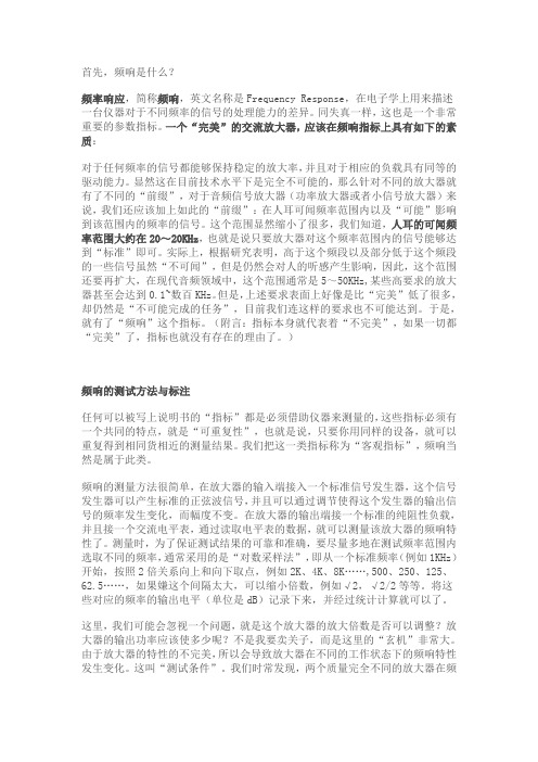
首先,频响是什么?频率响应,简称频响,英文名称是Frequency Response,在电子学上用来描述一台仪器对于不同频率的信号的处理能力的差异。
同失真一样,这也是一个非常重要的参数指标。
一个“完美”的交流放大器,应该在频响指标上具有如下的素质:对于任何频率的信号都能够保持稳定的放大率,并且对于相应的负载具有同等的驱动能力。
显然这在目前技术水平下是完全不可能的,那么针对不同的放大器就有了不同的“前缀”,对于音频信号放大器(功率放大器或者小信号放大器)来说,我们还应该加上如此的“前缀”:在人耳可闻频率范围内以及“可能”影响到该范围内的频率的信号。
这个范围显然缩小了很多,我们知道,人耳的可闻频率范围大约在20~20KHz,也就是说只要放大器对这个频率范围内的信号能够达到“标准”即可。
实际上,根据研究表明,高于这个频段以及部分低于这个频段的一些信号虽然“不可闻”,但是仍然会对人的听感产生影响,因此,这个范围还要再扩大,在现代音频领域中,这个范围通常是5~50KHz,某些高要求的放大器甚至会达到0.1~数百KHz。
但是,上述要求表面上好像是比“完美”低了很多,却仍然是“不可能完成的任务”,目前我们连这样的要求也不可能达到。
于是,就有了“频响”这个指标。
(附言:指标本身就代表着“不完美”,如果一切都“完美”了,指标也就没有存在的理由了。
)频响的测试方法与标注任何可以被写上说明书的“指标”都是必须借助仪器来测量的,这些指标必须有一个共同的特点,就是“可重复性”,也就是说,只要你用同样的设备,就可以重复得到相同货相近的测量结果。
我们把这一类指标称为“客观指标”,频响当然是属于此类。
频响的测量方法很简单,在放大器的输入端接入一个标准信号发生器,这个信号发生器可以产生标准的正弦波信号,并且可以通过调节使得这个发生器的输出信号的频率发生变化,而幅度不变。
在放大器的输出端接一个标准的纯阻性负载,并且接一个交流电平表,通过读取电平表的数据,就可以测量该放大器的频响特性了。
频率响应的英文缩写

频率响应的英文缩写频率响应的英文缩写是FR(Frequency Response)。
频率响应是指系统对不同频率输入信号的响应情况。
在信号处理中,频率响应是一个重要的指标,能够衡量系统对不同频率信号的增益或衰减程度。
具体来说,频率响应描述了系统在不同频率下输出信号与输入信号的幅度和相位关系。
它可以用来评估系统的稳定性、性能和准确度。
频率响应通常以图形的方式展示,称为频率响应曲线。
曲线的横轴表示频率,纵轴表示增益或相位。
在频率响应曲线上,可以清楚地看到系统在不同频率下的特性。
频率响应曲线通常具有以下基本特征:1.通频带:频率响应曲线的宽度被称为通频带。
通频带表示系统可以传输的最高频率和最低频率之间的范围。
一个好的系统应该具有宽阔的通频带,以保证信号的完整性。
2.增益:频率响应曲线上的峰值表示系统对特定频率的增益。
增益是输出信号幅度与输入信号幅度的比值。
增益可以是正值或负值,取决于系统是放大还是衰减输入信号。
在设计电子设备或音响系统时,需要根据需求确定增益的大小。
3.相位延迟:频率响应曲线上的相位表示系统对不同频率输入信号的延迟情况。
相位延迟是指输出信号与输入信号之间的时间差。
相位延迟对于某些应用是非常重要的,比如音频信号的同步和滤波器的设计。
频率响应在不同领域有着广泛的应用。
在音频领域,频率响应可以用于调整音响系统的声音效果,使得音乐更加动听。
在通信领域,频率响应可以用于设计滤波器和调制解调器,以保证信号传输的质量和稳定性。
在图像处理领域,频率响应可以用于图像增强和去噪处理。
为了获得良好的频率响应,需要合理选择系统中的元件和参数。
比如,对于音响系统,可以选择高质量的扬声器和放大器,以确保频率响应曲线的平滑和增益的稳定。
此外,还可以使用数字信号处理技术来控制和优化频率响应。
总之,频率响应是评估系统性能的重要指标,它描述了系统对不同频率输入信号的响应情况。
频率响应曲线能够提供有关系统增益、相位和通频带的信息,以指导系统设计和优化。
- 1、下载文档前请自行甄别文档内容的完整性,平台不提供额外的编辑、内容补充、找答案等附加服务。
- 2、"仅部分预览"的文档,不可在线预览部分如存在完整性等问题,可反馈申请退款(可完整预览的文档不适用该条件!)。
- 3、如文档侵犯您的权益,请联系客服反馈,我们会尽快为您处理(人工客服工作时间:9:00-18:30)。
11Frequency Response 11.1 Introduction 11.2 Linear Frequency Response Plotting 11.3 Bode Diagrams 11.4 A Comparison of Methods The IEEE Standard Dictionary of Electrical and Electronics Terms defines frequency response in stable, linear systems to be “the frequency-dependent relation in both gain and phase difference between steady-state sinu-soidal inputs and the resultant steady-state sinusoidal outputs” [IEEE, 1988]. In certain specialized applications,the term frequency response may be used with more restrictive meanings. However, all such uses can be related back to the fundamental definition. The frequency response characteristics of a system can be found directly from its transfer function. A single-input/single-output linear time-invariant system is shown in Fig. 11.1.For dynamic linear systems with no time delay, the transfer function H (s ) is in the form of a ratio of polynomials in the complex frequency s ,where Kis a frequency-independent constant. For a system in the sinusoidal steady state, s is replaced by thesinusoidal frequencyj w (j =) and the system function becomes H (j w ) is a complex quantity. Its magnitude, ΈH (j w )Έ, and its argument or phase angle, arg H (j w ), relate,respectively, the amplitudes and phase angles of sinusoidal steady-state input and output signals. Using the terminology of Fig. 11.1, if the input and output signals arex (t ) = X cos (w t + Q x )y (t ) = Y cos (w t + Q y )then the output’s amplitude Y and phase angle Q y are related to those of the input by the two equationsY = ΈH (j w )ΈXQ y = arg H (j w ) + Q x-1Paul NeudorferSeattle UniversityThe phrase frequency response characteristics usuallyimplies a complete description of a system’s sinusoidalsteady-state behavior as a function of frequency. BecauseH (j w ) is complex and, therefore, two dimensional in nature,frequency response characteristics cannot be graphically dis-played as a single curve plotted with respect to frequency.Instead, the magnitude and argument of H (j w ) can be sep-arately plotted as functions of frequency. Often, only the magnitude curve is presented as a concise way of character-izing the system’s behavior, but this must be viewed as an incomplete description. The most common form for such plots is the Bode diagram (developed by H.W. Bode of Bell Laboratories), which uses a logarithmic scale for frequency. Other forms of frequency response plots have also been developed. In the Nyquist plot (Harry Nyquist, also of Bell Labs), H (j w ) is displayed on the complex plane, Re[H (j w )] on the horizontal axis, and Im[H (j w )] on the vertical. Frequency is a parameter of such curves. It is sometimes numerically identified at selected points of the curve and sometimes omitted. The Nichols chart (N.B. Nichols) graphs magnitude versus phase for the system function. Frequency again is a parameter of the resultant curve,sometimes shown and sometimes not.Frequency response techniques are used in many areas of engineering. They are most obviously applicable to such topics as communications and filters, where the frequency response behaviors of systems are central to an understanding of their operations. It is, however, in the area of control systems where frequency response techniques are most fully developed as analytical and design tools. The Nichols chart, for instance, is used exclusively in the analysis and design of feedback control systems.The remaining sections of this chapter describe several frequency response plotting methods. Applications of the methods can be found in other chapters throughout the Handbook .Linear frequency response plots are prepared most directly by computing the magnitude and phase of H (j w )and graphing each as a function of frequency (either f or w ), the frequency axis being scaled linearly. As an example, consider the transfer functionFormally, the complex frequency variable s is replaced by the sinusoidal frequency j w and the magnitude and phase found.The plots of magnitude and phase are shown in Fig. 11.2.FIGURE 11.1 A single-input/single-output lin-ear system.A Bode diagram consists of plots of the gain and phase of a transfer function, each with respect to logarithmically scaled frequency axes. In addition, the gain of the transfer function is scaled in decibels according to the definitionThis definition relates to transfer functions which are ratios of voltages and/or currents. The decibel gain between two powers has a multiplying factor of 10 rather than 20. This method of plotting frequency response information was popularized by H.W. Bode in the 1930s. There are two main advantages of the Bode approach.The first is that, with it, the gain and phase curves can be easily and accurately drawn. Second, once drawn,features of the curves can be identified both qualitatively and quantitatively with relative ease, even when those features occur over a wide dynamic range. Digital computers have rendered the first advantage obsolete. Ease of interpretation, however, remains a powerful advantage, and the Bode diagram is today the most common method chosen for the display of frequency response data.A Bode diagram is drawn by applying a set of simple rules or procedures to a transfer function. The rules relate directly to the set of poles and zeros and/or time constants of the function. Before constructing a Bode diagram, the transfer function is normalized so that each pole or zero term (except those at s = 0) has a dc gain of one. For instance:Figure 11.2Linear frequency response curves of H (j w).ΈΈ ΈΈH H H j dB dB ==2010log ( )wIn the last form of the expression, t z =1/w z and t p =1/w p . t p is a time constant of the system and s = –w p is the corresponding natural frequency. Because it is understood that Bode diagrams are limited to sinusoidal steady-state frequency response analysis, one can work directly from the transfer function H (s ) rather than resorting to the formalism of making the substitution s = j w.Bode frequency response curves (gain and phase) for H (s ) are generated from the individual contributions of the four terms K ¢, s t z + 1, 1/s , and 1/(s t p + 1). As described in the following paragraph, the frequency response effects of these individual terms are easily drawn. To obtain the overall frequency response curves for the transfer function, the curves for the individual terms are added together.The terms used as the basis for drawing Bode diagrams are found from factoring N (s ) and D (s ), the numerator and denominator polynomials of the transfer function. The factorization results in four standard forms. These are (1) a constant K; (2) a simple s term corresponding to either a zero (if in the numerator) or a pole (if in the denominator) at the origin; (3) a term such as (s t + 1) corresponding to a real valued (nonzero) pole or zero; and (4) a quadratic term with a possible standard form of [(s/w n )2 + (2z /w n )s + 1] corresponding to a pair of complex conjugate poles or zeros. The Bode magnitude and phase curves for these possibilities are displayed in Figs. 11.3–11.5. Note that both decibel magnitude and phase are plotted semilogarithmically. The frequency axis is logarithmically scaled so that every tenfold, or decade , change in frequency occurs over an equal distance. The magnitude axis is given in decibels. Customarily, this axis is marked in 20-dB increments.Positive decibel magnitudes correspond to amplifications between input and output that are greater than one (output amplitude larger than input). Negative decibel gains correspond to attenuation between input and output.Figure 11.3 shows three separate magnitude functions. Curve 1 is trivial; the Bode magnitude of a constant K is simply the decibel-scaled constant 20 log 10 K , shown for an arbitrary value of K = 5 (20 log 10 5 = 13.98).Phase is not shown. However, a constant of K > 0 has a phase contribution of 0° for all frequencies. For K <0, the contribution would be ±180° (Recall that –cos q = cos (q ± 180°). Curve 2 shows the magnitude frequency response curve for a pole at the origin (1/s ). It is a straight line with a slope of –20 dB/decade. The line passes through 0 dB at w = 0 rad/s. The phase contribution of a simple pole at the origin is a constant –90°, independent of frequency. The effect of a zero at the origin (s ) is shown in Curve 3. It is again a straight line that passes through 0 dB at w = 0 rad/s; however, the slope is +20 dB/decade. The phase contribution of a simple zero at s = 0 is +90°, independent of frequency.Figure 11.3Bode magnitude functions for (1) K = 5, (2) 1/s , and (3) s.Note from Fig. 11.3 and the foregoing discussion that in Bode diagrams the effect of a pole term at a given location is simply the negative of that of a zero term at the same location. This is true for both magnitude and phase curves.Figure 11.4 shows the magnitude and phase curves for a zero term of the form (s /w z + 1) and a pole term of the form 1/(s /w p + 1). Exact plots of the magnitude and phase curves are shown as dashed lines. Straight line approximations to these curves are shown as solid lines. Note that the straight line approximations are so good that they obscure the exact curves at most frequencies. For this reason, some of the curves in this and later figures have been displaced slightly to enhance clarity. The greatest error between the exact and approximate magnitude curves is ±3 dB. The approximation for phase is always within 7° of the exact curve and usually much closer. The approximations for magnitude consist of two straight lines. The points of intersection between these two lines (w = w z for the zero term and w = w p for the pole) are breakpoints of the curves. Breakpoints of Bode gain curves always correspond to locations of poles or zeros in the transfer function.In Bode analysis complex conjugate poles or zeros are always treated as pairs in the corresponding quadratic form [(s /w n )2 + (2z /w n )s + 1].1 For quadratic terms in stable, minimum phase systems, the damping ratio z (Greek letter zeta) is within the range 0 < z < 1. Quadratic terms cannot always be adequately represented by straight line approximations. This is especially true for lightly damped systems (small z ). The traditional approach was to draw a preliminary representation of the contribution. This consists of a straight line of 0 dB from dc up to the breakpoint at w n followed by a straight line of slope ±40 dB/decade beyond the breakpoint,depending on whether the plot refers to a pair of poles or a pair of zeros. Then, referring to a family of curves as shown in Fig. 11.5, the preliminary representation was improved based on the value of z . The phase contribution of the quadratic term was similarly constructed. Note that Fig. 11.5 presents frequency response contributions for a quadratic pair of poles. For zeros in the corresponding locations, both the magnitude and phase curves would be negated. Digital computer applications programs render this procedure unnecessary for purposes of constructing frequency response curves. Knowledge of the technique is still valuable, however, in the qualitative and quantitative interpretation of frequency response curves. Localized peaking in the gain curve is a reflection of the existence of resonance in a system. The height of such a peak (and the corresponding value of z ) is a direct indication of the degree of resonance.Bode diagrams are easily constructed because, with the exception of lightly damped quadratic terms, each contribution can be reasonably approximated with straight lines. Also, the overall frequency response curve is found by adding the individual contributions. Two examples follow.1Several such standard forms are used. This is the one most commonly encountered in controls applications.Figure 11.4Bode curves for (1) a simple pole at s = –w p and (2) a simple zero at s = –w z.This chapter concludes with the frequency response of a simple system function plotted in three different ways.Example 3Figure 11.8 shows the direct, linear frequency response curves for T (s ). Corresponding Bode and Nyquist diagrams are shown, respectively, in Figs. 11.9 and 11.10.Figure 11.6Bode diagram of A (s ).Figure 11.7Bode diagram of G (s).Figure 11.8Linear frequency response plot of T(s).Figure 11.9Bode diagram of T(s).Figure 11.10Nyquist plot of T(s).Defining TermsBode diagram: A frequency response plot of 20 log gain and phase angle on a log-frequency base. Breakpoint: A point of abrupt change in slope in the straight line approximation of a Bode magnitude curve. Damping ratio:The ratio between a system’s damping factor (measure of rate of decay of response) and the damping factor when the system is critically damped.Decade:Synonymous with power of ten. In context, a tenfold change in frequency.Decibel: A measure of relative size. The decibel gain between voltages V1 and V2 is 20 log10(V1/V2). The decibel ratio of two powers is 10 log10(P1/P2).Frequency response:The frequency-dependent relation in both gain and phase difference between steady-state sinusoidal inputs and the resultant steady-state sinusoidal outputs.Nichols chart:Control systems — a plot showing magnitude contours and phase contours of the return transfer function referred to as ordinates of logarithmic loop gain and abscissae of loop phase angle. Nyquist plot: A parametric frequency response plot with the real part of the transfer function on the abscissa and the imaginary part of the transfer function on the ordinate.Resonance:The enhancement of the response of a physical system to a steady-state sinusoidal input when the excitation frequency is near a natural frequency of the system.Related Topics2.1 Step, Impulse, Ramp, Sinusoidal, Exponential, and DC Signals•100.3 Frequency Response Methods: Bode Diagram ApproachReferencesR.C. Dorf, Modern Control Systems, 4th ed., Reading, Mass.: Addison-Wesley, 1986.IEEE Standard Dictionary of Electrical and Electronics Terms, 4th ed., The Institute of Electrical and Electronics Engineers, 1988.D.E. Johnson, J.R. Johnson, and J.L. Hilburn, Electric Circuit Analysis, 2nd ed., Englewood Cliffs, N.J.: Prentice-Hall, 1992.B.C. Kuo, Automatic Control Systems, 4th ed., Englewood Cliffs, N.J.: Prentice-Hall, 1982.K. Ogata, System Dynamics, Englewood Cliffs, N.J.: Prentice-Hall, 1992.W.D. Stanley, Network Analysis with Applications, Reston, Va.: Reston, 1985.M.E. Van Valkenburg, Network Analysis, 3rd ed., Englewood Cliffs, N.J.: Prentice-Hall, 1974.Further InformationGood coverage of frequency response techniques can be found in many undergraduate-level electrical engi-neering textbooks. Refer especially to classical automatic controls or circuit analysis books. Useful information can also be found in books on active network design.Examples of the application of frequency response methods abound in journal articles ranging over such diverse topics as controls, acoustics, electronics, and communications.。