激光扫描焊缝跟踪器使用说明书(220V)
(完整word版)激光焊接机器人焊缝跟踪方法

激光焊接机器人焊缝跟踪控制方法陈智龙120160033摘要:当前激光焊接机器人在实际的工业生产中应用的越来越广泛,在汽车制造业以及其他机器制造业激光焊接机器人在生产中的作用也越来越大。
如何提高焊接机器人的焊缝精度问题以及控制焊缝轨迹已成为激光焊接机器人发展的首要难题。
关键词:激光焊接机器人;焊缝轨迹;控制0引言激光作为焊接和切割的新手段应用于工业制造,具有很大发展潜力。
在国际汽车工业领域,激光加工技术已广泛得到了应用,激光切割与焊接逐渐成为标准的汽车车身生产工艺.国内也已积极推广应用,但目前主要还是以引进成套激光加工设备为主,用于激光钎焊、激光渗透焊、激光对接焊、白车身激光三维切割和激光金属零件表面热处理[1]。
由于成本考虑,有些汽车厂家则直接进口国外激光加工的零部件.为提升我国汽车制造的技术能力,我们应依靠国内技术能力,自主创新,在更广范围和更深层次上,加快激光加工在制造业的应用发展.车身在整车制造中占有重要地位,不仅车身成本占整车的40%~50﹪,而且对汽车安全、节能、环保和快速换型有重要影响。
人口老龄化不断逼近,各制造业工厂着手进行技术改造工程设计,采用了许多工业机器人,以提高生产线的柔性程度为基础,为制造厂家提供了生产产品多样化,更新转型的可能性.以上汽大众汽车车身生产车间为例,机器人能独立完成工件的移动搬运、输送、组装夹紧定位,可完成工件的点焊、弧焊、激光焊、打磨、滚边、涂胶等工作.有的工位上把上件、夹具、工具以机器人为中心布置,以便机器人能完成多个工序,实现多品种、不同批量的生产自动化.采用机器人使焊接生产线更具柔性化、自动化,使多种车身成品可在一条车身装焊生产线上制造,实现多车型混线生产.因此,焊接生产线必须很容易地因产品结构、外形的改变而改变,具有较高的柔性程度[2].由于柔性车身焊接生产线可以适应汽车多品种生产及换型的需要,是汽车车身制造自动化的必然趋势,特别是进入上世纪90年代以后,各大汽车厂家都在考虑车身焊接生产线柔性化。
激光焊缝跟踪系统机器人用技术手册
Meta Vision Systems机器人用激光焊缝跟踪系统技术手册原作者:Jonathan Moore 翻译:Dr. Lin Sanbao (林三宝博士)前言尽管我们在编写这个手册时已经尽了最大努力,但是我们不接受任何由通过使用或者错误使用本手册中的信息,或者可能包含在本手册中的错误,而引发的责任和义务。
本手册所提供的信息只是用于培训的目的。
英文版权所有 © Meta Vision Systems 2000。
中文版版权所有© 中国哈尔滨AWPT-RDC联合实验室所有权力保留,未经允许,不得以任何形式复制本手册或本手册中的任何部分。
联系方式:Meta Vision Systems Ltd.Oakfield HouseOakfield Industrial EstateEynshamOxfordshireOX8 1THUNITED KINGDOMTel: +44 (0) 1865 887900Fax: +44 (0) 1865 887901Email: *******************.uk中国地区:地址:珠海市九洲大道兰埔白石路105号二楼西邮编:519000电话:0756 --- 8509695、8508516、6680610、6602419、6626464传真:0756 --- 8500745联系人:魏占静电邮:*************.cn***************网址:目录1.概述 (3)1.1传感头 (3)1.2控制系统 (3)1.3应用 (3)1.4典型应用 (4)1.5焊缝类型 (4)2.传感器 (9)2.1激光的安全性 (9)2.2规格 (9)2.3MT 产品系列的规格 (11)2.4传感器的物理规格 (12)2.5焊缝的特征尺寸 (12)3.控制系统 (14)3.1MTF – Finder(MTF 定位控制系统) (14)3.2MTR (15)3.3MTR Integrated(集成型MTR系统) (16)3.4MTX-HS (16)4.软件的主要特征 (18)4.1焊缝定义 (18)4.2间隙测量 (18)4.3真实路径(True Path) (18)4.4搜索 (18)4.5体积&高度错边测量 (19)4.6交替式激光器 (19)4.7示教跟踪(Teach Track) (20)5.配置和可选项 (21)5.1应用概述 (21)5.2硬件和软件可选项 (22)1. 概述Laser Pilot产品系列被设计用于为机器人应用提供导引技术的解决方案。
T3激光跟踪仪使用手册

目录第一章:坐标系介绍 (2)1.笛卡儿坐标系 (2)2.球坐标系 (4)3.柱坐标系 (4)第二章:API 激光跟踪仪III介绍 (6)1.API激光跟踪仪参数 (6)2.API激光跟踪仪组成 (8)3.激光跟踪仪的安全规程 (12)4.安装API 激光跟踪仪III (12)5.API激光跟踪仪原理 (14)第三章:TrackerCalib的使用 (17)1.TrackerClib软件介绍 (17)2.TrackerCalib软件的应用 (18)第四章:Spatial Analyzer的应用 (29)1.Spatial Analyzer介绍 (29)2.SA的安装 (29)3.SA连接激光跟踪仪 (33)4.SA跟踪仪界面介绍 (37)5.测量设置及点坐标采集 (52)6.跟踪仪一般设置 (56)第五单元:远程家点和配置反射镜及探针 (61)1.远程复位点 (61)2.在软件界面中添加SMR和探针 (63)第六单元:良好的测量原则 (68)第七章:创建特征形体 (70)1.构造点 (71)2.构造平面 (73)3.构造圆 (75)第八章:建立本地坐标系 (79)第九章:跟踪仪转站测量 (83)第十章:应用查询和组合 (86)1.查询单点或多个点之间的位置关系 (86)2.查询多个点到单点或对象 (88)第十一章:用关联比较组 (93)第十二章:比例补偿 (97)第十三章:测量报告 (99)1.快速报告 (99)2.GD&T报告 (101)3.HTML报告 (108)4.自定义报告模板 (109)第十四章:测量点与三维CAD模型最佳拟合 (113)第十五章:智能测头(I-Probe) (116)第十六章:智能扫描仪(I-Scan) (124)第一章:坐标系介绍理解坐标系是很重要的。
同样重要的是要熟悉三维空间的几何元素如线、面、圆和圆柱体以及每个实体是如何分解成简单几何元素的。
1.笛卡儿坐标系笛卡儿坐标系是有空间几何特征在相互正交的三个平面上投影而产生的,其特征如下:1.在二维几何中有X轴和Y轴;2.在三维几何中有X轴、Y轴和Z轴;3.各个轴是垂直相交的;4.各个轴上使用相同的距离单位。
激光跟踪仪操作规程
激光跟踪仪操作规程激光跟踪仪操作规程一、激光跟踪仪的安全规程1. 激光跟踪仪使用可见的、二级氦氖激光,考虑到人眼的安全不要长时间盯着看。
2. 不要把激光跟踪仪暴露在潮湿的环境中。
水进入系统会增加触电的风险,带来严重人身伤害。
3. 不要将激光跟踪仪暴露在严重粉尘污染的环境中,避免粉尘对仪器元件造成严重伤害。
4. 不要用手接触跟踪头的运动组件,否则会导致严重的人身伤害。
5. 确保电缆线的位置,防止踩上、绊倒、用锋利边缘或移动的物体与之接触,否则会损害或压迫电缆。
二、激光跟踪仪的安装操作1. 把三脚架放在一个稳定平衡的基础平面上,确保平面干净(无水或油污),不要有障碍物,紧固脚架锁紧螺母,把跟踪头安装在三脚架上。
2. 确保三脚架上颈口的锁紧螺母锁紧,同时紧固三脚架筒上调节高低的两个锁紧旋钮,检查三脚架的三个脚都接触平面(必要时用热熔胶固定)。
3. 把控制器放在一个接近跟踪仪和笔记本电脑而且方便的位置。
不得挡住控制器背面和底部的冷却风扇,否则会导致热量过多可能损坏部件。
4. 确保控制箱电源开关在关闭位置。
5. 在控制箱和激光跟踪头之间连接跟踪仪/控制箱电缆。
确保电缆位置防止踩上、绊倒、用锋利边缘或移动的物体与之接触,否则会损害或压迫电缆。
6. 在控制箱和电脑之间连接RJ45电缆(网线)。
7. 连接环境传感器单元到控制箱。
确保空气温度传感器自由悬挂没有与热源接触,否则会读到错误的周围温度。
确保材料温度传感器吸附在被测工件的光滑表面上,确保准确读到材料温度的信息。
8. 在控制箱与AC电源之间连接电源线。
确保连接的稳定性,保证工作期间不会断电,以免影响测量工作。
9. 打开控制箱电源开关,待响四声系统启动完毕声后,方可打开伺服系统开关。
(完成测量工作后,必须先关闭伺服系统开关,再关闭电源开关。
)10. 检查跟踪头上指示灯,红灯闪烁,说明仪器正在上电升温中,待红灯稳定,上电结束,方可开始测量工作。
制定:日期:审核:日期:。
SE2L2IDEC安全激光扫描器产品说明书
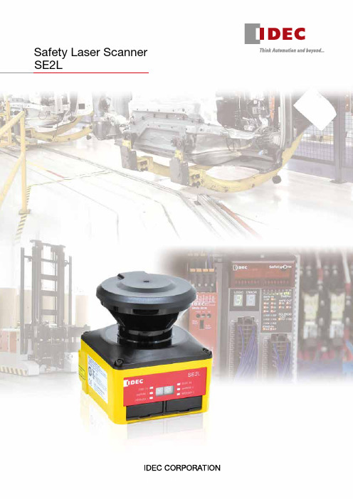
Safety Laser Scanner SE2L2IDEC’s safety products for safe and productive production linesStop area can be made smaller by detecting approach at the additional protection zone to start slowdown.(Conventional configuration of one protection zone +two warning zones is possible)RF1V force-guided relay(4-pole/6-pole)One SE2L protects a wide area (270º and 5m) and can be used in a variety of applications such as large sized systems or long conveyor lines.*1: average stride length (70 cm) of a 170 cm personCan interrupt a small load directly.Area Protection Ensures the safety of humans in a hazardous area, or those approaching the machine.RF2 force-guided relay (2-pole)Can be used as interface relays to send inputsignals to a controller, or to amplify current for driving a contactor.∗1A maximum of four SE2Ls can be interconnected using RS-485 for master/slave operation.3An SE2L can monitor two separate hazardous areas to stop machines when detecting the access of humans. No reflective sensor is necessary, thus eliminating the need of optical axis alignment. Can replace two light curtains.FS1A Safety ControllerLD6A LED SignaLight TowersReference monitoring function ensures safety bydetecting the positional change of SE2L or reference boundary, such as a door’s opening/closing status.Dual protection function A variety of safety products can be connected to the controller equipped with various control logics.Used to indicate the status ofprocesses. Visible even at a distance.By disabling some areas of protection zone, muting function allows objects to enter the hazardous area without stopping the machine.With override function, when stopped by errors at muting status, the work can be moved easily.Access Protection Allows only objects to pass through. Detects the access of humans.Utilize distance measurement dataA maximum of 32 area patterns can be configured/switched according to the mobile application suchas AGV, ensuring the optimum protection in variousapplications.EDM function monitors the status of externaldevices, enabling monitoring of welded contacts andsuch.Pulse signals from an incremental encoder can be sentto the SE2L directly without a controller, enabling toswitch areas easily depending on the speed.During safety protection, the SE2L can send outdistance measurement data through the Ethernetport, in order to obtain the data of the obstacles.Emergency Stop SwitchesXW/XN/X6A variety of models to choose from.Force-guided relayCollision AvoidanceIDEC’s safety productsfor safe and productiveproduction linesProtects humans from colliding.Also prevents loads on fromfalling.45Operational status is displayed on the SE2L. It can also be displayed on PC to monitor errors and data log for easy trouble shooting.Checks dust in air with signals and reduces unintendeddetection. Safety function is not impaired.Easy-to-use configuration and useful functions for simple and comfortable maintenance.IDEC Safety Solution− Safety system − Safety consulting − Risk assessment − Safety seminarsOptical window can be replaced by the user, reducing downtime and cost. A cover bracket to protect the SE2L for damage by collision is also available.Cover Bracket Optical WindowIDEC —Committed to creating the optimum safety environment —both for humans and systems.SE2L Safety Laser ScannerPackage Quantity: 1• See product catalogs or IDEC's website for detailed part no.Safety Products6SE2L Safety Laser ScannerNote 2: Additional distance of 200 mm is needed when the SE2L operates under high reflective background.Note 3: Total current supply of OSSD output and warning output should be below 1.0A.Note 4: The angle between the sensing plane and the light source should be more than 5 degrees.78SE2L Safety Laser ScannerAll dimensions in mm.DimensionsSafety Laser ScannerCover BracketSE9Z-HS2-CM01• Used to protect the optical window in combina-tion with base mounting bracket or rear mounting bracket.96.250254-M515ø854090.77091817(10)(30)29.53321Rear Mounting BracketSE9Z-HS2-BK026866204548.22513415061.225(93.2)(101.2)284-ø5.3SE2L Mounting Holes4-ø5.3Cover Bracket Mounting Holes7.5°7.5°7.5°7.5°Base Mounting BracketSE9Z-HS2-BK011106860286611013010(18)3-ø5.3604570257.5°7.5°48.225364-ø5.3 SE2L Mounting Holes4-ø5.3Cover Bracket Mounting Holes9SE2L Safety Laser ScannerWiring Examplesa) When using 32 scanning areas (e.g. AGV)b) When using muting/override/EDMc) When switching 32 scanning areas using an encoderIDEC safety products Safety Controller: FS1A E-STOP: X seriesIDEC safety productsSignaLight w/alarm: LD6A PLC: FC6A LED pilot light: AP22Force-guided relay: RF2IDEC safety productsSignaLight w/alarm: LD6A PLC: FC6A Muting sensor: SA1E Muting sensor lamp: HW1P-5Force-guided relay:RF210SE2L Safety Laser ScannerInput/Output CircuitOSSD/WARNING outputs are Nchannel MOSFET outputs.Input CircuitAvailable for are input, EDM1, EDM2, RESET1, RESET2, MUTING1, MUTING2, MUTING3, MUTING4, OVERRIDE1, and OVERRIDE2.RES_REQ1, RES_REQ2, MUT_OUT1, MUT_OUT2 outputs are PNP outputs.IDEC safety products SignaLight w/alarm: LD6A PLC: FC6A LED pilot light: AP22Safety Controller: FS1A E-STOP: X seriesIDEC safety productsSignaLight w/alarm: LD6A PLC: FC6A LED pilot light: AP22Safety Controller: FS1A E-STOP: X seriesd) When using the master slave function to guard an AGV or robote) When using the master slave function to guard multiple hazards and perform partial stopsOSSD/WARNING Output CircuitOther Output Circuit11Operating PrincipleWith the SE2L, the distance is measured by the Time of Flight (TOF) principle. The SE2L sends out very short pulses of infrared light. The mirror rotated by the motor sends the infrared light within the scanning range of 270º, and is reflected back from an object within the range.The distance can be calculated as follows:L =1−2× c × TL = Distance to the object c = Speed of lightT = Time differenceArea SwitchingThe SE2L can store up to 32 area patterns. The number of maximum configurable areas depends on selected functions such as scan area mode and muting.Scanning AreaA scanning area of the SE2L consists of:• A protection + two zones • A protection zone • Two protection zonesUp to 32 sets of scanning areas can be configured.A software SLS Project Designer supplied with the SE2L is used to configure the protection and warning zones, providing excellent user interface. Automatic zoneconfiguration by referring the boundary is also possible. See SE2L User's Manual “7. Function Configuration of SE2L” for details. The latest version of the software can bedownloaded from IDEC website.Protection zone: The area obtained by risk assessmentand calculation of safety distanceWarning zone: The area to send alarms which can beset according to the applicationArea previewArea commentResponse time (ON/OFF)Area selectionPoint coordinateArea display Mouse positionZoom-in, zoom-out toolDrawing tools barNote 1: Dual protection and muting function modes cannot beused when encoder input mode is selected.Note 2: Among the four input patterns, at least one pattern mustbe used for encoder input. Other three remaining patterns can be selected to be used as a static input or not in use. A pattern with encoder input mode has up to 32 sets of area.Input combination for area switching(ex. 5 inputs)Response TimeThe OFF response time (default: 60ms) for the OSSD signaland ON response time (default: 270ms) can be configuredby using the SLS Project Designer. The response time forWARNING 1, 2 is the same as the response time for OSSD.In dual protection mode, different response time can beset for protection zone 1 and 2 each. The stability of theSE2L can be increased by setting a long response time,but a long safety distance is required (see User's Manual4. Application Examples of SE2L). Before setting theresponse time, the user must perform a risk assessmentthoroughly. The configurable response time is shown in thetable below. Be sure to add the time taken to switch areas(30 ms).Time ChartObjectpresentObjectabsentOSSDONOFFOFF Response Time ON Response TimeObjectDetectionSE2L Response Time• Minimum configurable response time in Master/Slave modeOFF: 120ms, ON: 300msSafety DistanceAccess protectionIn this application, the SE2L is horizontally installed toprotect the hazardous area. The protection zone is setaround the hazardous area to prevent humans or objectsfrom entering the hazardous area. Warning zones 1 and 2are configured to surround the protection zone.Protection zone 1 application(horizontal, stationary installation)Warning zones 1 and 2 are set around the protectionzone to send alarms to prevent humans or objects fromentering the hazardous area and stopping the machine. Bydetecting humans or objects in the protection zone, theOSSD signal switches from ON to OFF. Also, when humansor objects are detected in the warning zone, WARNINGsignal switches from ON to OFF.Upper view (stationary)• Maintain the distance “a” shorter than the minimumdetection width. To prevent unwanted detection, maintainthe distance "b" 100mm.Side view (stationary)CalculationS = (K × (T m + T s) + C + Z sS = Safety distance (mm)K = Human approach speed 1,600 (mm/s)T m = Maximum stop speed of machine or system (s)1213InstallationLight InterferenceSE2L is a sensor that transmits pulsed laser for obstacle detection. Interfering light sources may lead to falsedetection. Before using the SE2L, examine the surrounding environment. If the SE2L must be used under theenvironment shown below, install the SE2L so that the light source is located more than ±5 degrees from the sensing plane to prevent light interference.a) Incandescent light b) F lorescent light c) Strobe lightd) F lashing beacon e) Sunlightf) Infrared light sourceplane Detectionorigin pointMutual InterferenceWhen using several safety laser scanners or scanning range finders of the same model, pulse laser signals from other sensors may be falsely detected. To prevent mutual interference, see the installation methods shown below. See User's Manual for more details.1) Changing the installation heightInstall the SE2Ls at different heights to keep at least 5 degree distance between the detection planes. ①Face to face installation5° or more5° or moreDetection planeDetection plane②Parallel installation5° or more 5° or moreDetection planeDetection plane2) Changing the installation angleAdjust the angle of SE2Ls to keep at least 5 degree distance between the detection planes.①Face to face installation5° or moreD e t e c t ion p la n eD e t e c t ion p la n e②Parallel installation5° or moreD e t e c t io np la n eD e t e c t ion p la n e3) Using shieldsInstall a shield between the SE2Ls to prevent prevent the laser beams from entering the other SE2L.①Face to face installation②Parallel installation14Highly Reflective BackgroundHighly reflective backgrounds may cause false detection causing the SE2L to detect a longer distance than the actual distance. If an operating environment with a highly reflective background cannot be avoided, an additional distance of 200 mm is needed when configuring protection or warning zones.* Additional distance: the distance required to operate the SE2L under high reflective backgroundLimited Detection Capability AreaThe limited detection capability area is the area between the optical window and the beginning of the detection zone. The area from the origin point of the SE2L to 90 mm from the origin point is the limited detection capability area.In this area, a low reflective object is difficult to detect.WiringThe table below shows the functions of each wire. Use of a shielded wire is recommended.15OSSDIn SE2Ls, the OSSD signal has a self-diagnosis function that tests the signal periodically to detect malfunction. The OSSD signal will turn OFF when a error is detected due to the self-diagnosis function. The self-diagnosis function of the OSSD detects abnormality by switching off OSSD 1 to OSSD 4 at intervals of 300 µs maximum. Be sure to use a force-guided relay, converter, or controller that does not respond to this self-diagnosis function.Time chartOperating Environmentx Make sure that the operating environment is within the range of the specifications (temperature, humidity, light interference) described in User’s Manual, otherwisemalfunction or degradation of detection performance may result.x Do not use the SE2L near a machine that may generate strong radio waves. It may interfere with the operation of the SE2L.x Do not use or install the SE2L where dust, smoke, or corrosive chemical substances exist. Using the SE2L under these environments may lead to degradation of detection performance.x The SE2L is for indoor use only.Installationx Install the SE2L on a stable surface or structure to prevent displacement of the sensor.x Install the SE2L securely so that screws do not loosen due to shock or vibration. (Recommended tightening torque 3 N∙m). Displacement may degrade protection performance.x Determine the safety distance before installing the SE2L. After installing the SE2L, use a test piece for all protection zones to check the sensing functions.x After installing the SE2L, use protective materials such as safety guards and light curtains to prevent entry into the protective zone.x The following switches must be installed far from the protection zone, so that the operator can operate the switches while overseeing the entire protection zone.* Switch to reset the interlock function * Switch to start muting function * Switch to start override functionx If several SE2Ls are installed on the same sensing plane, mutual interference may occur.x Provide enough space for installation and maintenance of the SE2L.x Do not cover the front of the optical window with glass or transparent cover, otherwise detection characteristics of the SE2L may be impaired.x Minimum sensing width differs according to the distance.For correct use of the SE2L, take note of the following precautions.x SE2L is a AOPDDR (Active Optoelectronic Protective Device responsive to Diffuse Reflection) that detects diffused emitted light within the protection zone.x Perform tests before operation to check the function and performance of the SE2L.x SE2L is designed to protect human beings or systems by monitoring the hazardous area. It is not designed for the protection from high speed objects or electromagnetic radiation.x To maintain the degree of protection and to prevent injury or death, do not modify or disassemble the SE2L.x IDEC does not warrant any problems that were caused by modification or disassembly of the SE2L.x The operator must be a person qualified to operate the SE2L. The operator must be trained and be able to operate the SE2L correctly.x The administrator must provide continuous training to the operator for correct use of the SE2L.x The administrator must understand the user's manual and be responsible for ensuring appropriate operating conditions for SE2L.x SE2L has been manufactured and shipped under strict quality control. If you find any defect in the product, contact distributor or sales representative.x IDEC does not take responsibility for damage caused by improper use of the product by customers or third parties. IDEC cannot take responsibilities for any loss from the misuse except for the responsibilities governed by law.x To examine the object detecting performance, use a test piece the size equivalent to the minimum detectable object.x Error occurs when detection capability is below 30% due to homogenous dirt on the optical window. The operator must keep the windows clean.x When the interlock function is active, make sure that the surrounding environment, especially within the protection zone, is safe before resetting the interlock.x While SE2L is removed, a protective measure must be taken to ensure safety within the protection zone. To prevent entry into the danger zone, use protective materials such as a safety guard or light curtain. x SE2L and its accessories are subject to change for improvement without prior notice.x Dispose the SE2L as industrial waste or in accordance with the local regulations.OSSD1OSSD2OSSD3OSSD4Wiringx Be sure to turn off all power before wiring.x When using converter power, make sure to use power that satisfies the following requirements.1) The rated output voltage is within 24V DC±10% (SELVcircuit, overvoltage category II)2) The circuit between primary circuit and secondarycircuit is reinforced insulation or double insulation.3) The output holding time is 20 ms.4) The power supply must comply with electrical safetyand electromagnetic compatibility (EMC) regulationsrequirements of each country, state, and district.x All input/output cables must be located away from power cables and high voltage cables.x To control safety-related machine or system, use OSSD output. Because warning zone output (warning signal) is a non-safety signal, do not use for safety purposes.x Both the OSSD1 and OSSD2 outputs should be connected to safety-related machines or control system. When OSSD3 and OSSD4 are used, connect the outputs in the same manner.x Use shielded cable for the connection between OSSD signals and safety-related machines or systems.Installationx A password is used for configuring the safety function. Only an administrator or operator should be able to set safety functions.x SE2L will not operate without initial configuration.x Perform test operation and check the configuration before using the SE2L.x The stability of the SE2L increases by delaying the response time of the OSSD signal but the sensing performance decreases for moving objects. Before using this function, be sure to carry out risk assessment.x The operator must record the changes made in the configuration. SLS Configurator report function is available. For details, see the User's Manual.Testing and Maintenancex The operator should perform the following tests or maintenance based on the checklist described in the User's Manual.1) Pre-operation inspection2) Operation inspection3) Daily inspection4) Periodic inspectionThe checklist in the User's Manual is a basic guideline for performing tests and maintenance. The operator should perform additional tests and maintenance if necessary.x Stop the machine if failure occurs during tests.x Clean the optical window if any dirt is found, and ask for repair if damaged. Refer to the User's Manual for details.。
国产激光跟踪仪安全操作及保养规程

国产激光跟踪仪安全操作及保养规程简介国产激光跟踪仪是一种用于测量目标物体位置的设备,可以广泛应用于各种实验、测试、生产等领域。
但如果操作不当或者无法得到良好的保养维护,不仅会降低仪器的性能和寿命,也会存在潜在的安全隐患。
因此,本文将介绍国产激光跟踪仪的安全操作规程和保养规程。
安全操作规程对于任何设备,安全才是首要考虑的因素,国产激光跟踪仪也不例外。
以下是国产激光跟踪仪的安全操作规程。
1.穿戴防护装备白色激光的功率普遍较大,因此在操作时务必戴上辐射防护眼镜,避免激光直接照进眼睛。
同时,要确保操作人员穿戴合适的防护服、手套等,避免接触到可能有危害的化学品或其他危险物品。
2.确认工作环境是否安全在进行实验或测试前,一定要检查工作环境是否安全。
首先要检查机器是否处于正确的位置,并确保设备周围没有可能影响操作的障碍物。
此外,也需要注意测量周围环境是否存在对仪器产生影响的其他设备或机械。
如果存在任何不安全的情况,应当先进行处理,并确认工作环境符合安全标准后,再进行操作。
3.正确操作设备在进行实验或测试时,必须仔细阅读并遵守设备的使用说明书。
在使用过程中,要注意激光束的方向和射程、光束的强度大小等指标,确保操作过程中不会对周围人员、设备及其它物品造成危害。
另外,如果在操作过程中发现任何不正常的情况,应立即停止操作,查明原因并排除故障。
4.设备归位和断电当完成使用后,必须正确地归位仪器,并拔掉电源插头。
此时,务必确保设备处于安全状态,并清理干净工作区域,不留任何危险因素。
保养规程除了注意安全操作外,好的保养也对仪器性能和寿命有重要影响。
下面是国产激光跟踪仪的保养规程。
1.定期清洁设备清洁设备是保持激光跟踪仪良好工作状态的关键之一。
因此,必须定期维护清洁设备。
在清洁过程中,应注意避免用过于湿润的布或纸来擦拭设备的表面以及镜头等,以免受到潮气的影响。
同时,也不应该用过于刮擦的物品来清洁表面,以防刮伤设备的表面和镜片。
激光焊缝跟踪系统机器人用技术手册讲解

本文由【中文word文档库】搜集整理。
中文word文档库免费提供海量教学资料、行业资料、范文模板、应用文书、考试学习和社会经济等word文档Meta Vision Systems机器人用激光焊缝跟踪系统技术手册原作者:Jonathan Moore 翻译:Dr. Lin Sanbao (林三宝博士)前言尽管我们在编写这个手册时已经尽了最大努力,但是我们不接受任何由通过使用或者错误使用本手册中的信息,或者可能包含在本手册中的错误,而引发的责任和义务。
本手册所提供的信息只是用于培训的目的。
英文版权所有 © Meta Vision Systems 2000。
中文版版权所有© 中国哈尔滨AWPT-RDC联合实验室所有权力保留,未经允许,不得以任何形式复制本手册或本手册中的任何部分。
联系方式:Meta Vision Systems Ltd.Oakfield HouseOakfield Industrial EstateEynshamOxfordshireOX8 1THUNITED KINGDOMTel: +44 (0) 1865 887900Fax: +44 (0) 1865 887901Email: support@中国地区:地址:珠海市九洲大道兰埔白石路105号二楼西邮编:519000电话:0756 --- 8509695、8508516、6680610、6602419、6626464传真:0756 --- 8500745联系人:魏占静电邮:jbw@ wzj0756@网址:目录1.概述 (4)1.1传感头 (4)1.2控制系统 (4)1.3应用 (4)1.4典型应用 (5)1.5焊缝类型 (5)2.传感器 (10)2.1激光的安全性 (10)2.2规格 (10)2.3MT 产品系列的规格 (12)2.4传感器的物理规格 (13)2.5焊缝的特征尺寸 (13)3.控制系统 (15)3.1MTF – Finder(MTF 定位控制系统) (15)3.2MTR (16)3.3MTR Integrated(集成型MTR系统) (17)3.4MTX-HS (17)4.软件的主要特征 (19)4.1焊缝定义 (19)4.2间隙测量 (19)4.3真实路径(True Path) (19)4.4搜索 (19)4.5体积&高度错边测量 (20)4.6交替式激光器 (20)4.7示教跟踪(Teach Track) (21)5.配置和可选项 (22)5.1应用概述 (22)5.2硬件和软件可选项 (23)1. 概述Laser Pilot产品系列被设计用于为机器人应用提供导引技术的解决方案。
西克安全激光扫描仪microScan3 Core I O AIDA 操作指南说明书
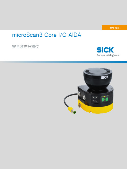
microScan3 Core I/O AIDA 安全激光扫描仪所述产品microScan3 Core I/O AIDA制造商SICK AGErwin-Sick-Str.179183 Waldkirch, Germany德国法律信息本文档受版权保护。
其中涉及到的一切权利归西克公司所有。
只允许在版权法的范围内复制本文档的全部或部分内容。
未经西克公司的明确书面许可,不允许对文档进行修改、删减或翻译。
本文档所提及的商标为其各自所有者的资产。
© 西克公司版权所有。
原始文档本文档为西克股份公司的原始文档。
2操作指南 | microScan3 Core I/O AIDA8025406/1L9Q/2023-08-14 | SICK如有更改,恕不另行通知内容内容1关于本文档的 (7)1.1本文件的功能 (7)1.2适用范围 (7)1.3本操作指南的目标群体 (7)1.4更多信息 (7)1.5图标和文档规范 (8)2安全信息 (9)2.1基本安全提示 (9)2.2规定用途 (10)2.3不当使用 (10)2.4网络安全 (11)2.5合格的安全人员 (11)3产品说明 (12)3.1通过 SICK Product ID 标识产品 (12)3.2设备概览 (12)3.3结构和功能 (13)3.4产品特性 (14)3.4.1变型 (14)3.4.2接口 (15)3.4.3系统插头 (15)3.4.4区域类型 (15)3.4.5区域组 (17)3.5应用示例 (17)4项目 (20)4.1机器制造商 (20)4.2机器的运营商 (20)4.3设计 (20)4.3.1防止干扰 (21)4.3.2避免无保护区域 (22)4.3.3安全激光扫描仪的响应时间 (24)4.3.4参考轮廓监控 (24)4.3.5危险区域保护 (26)4.3.6危险点保护 (32)4.3.7访问保护 (35)4.3.8动态危险区域保护 (37)4.4与电气控制系统的连接 (42)4.4.1电磁兼容性 (43)4.4.2电压供给 (44)4.4.3USB 接口 (44)4.4.4OSSD (44)4.4.5电路示例 (45)8025406/1L9Q/2023-08-14 | SICK操作指南 | microScan3 Core I/O AIDA3如有更改,恕不另行通知内容4.5检查方案 (45)4.5.1调试中和特殊情况下的检查规划 (46)4.5.2定期检查的规划 (46)4.5.3检查提示 (47)5装配 (49)5.1安全性 (49)5.2拆封 (49)5.3安装流程 (49)5.3.1直接安装 (51)6电气安装 (52)6.1安全性 (52)6.2接口概览 (53)6.2.1microScan3 Core (53)6.3接口配置 (53)6.3.1带 M12 插塞接头的连接电缆 (54)6.3.2备用 FE 接口 (54)7系统配置 (55)7.1交货状态 (55)7.2Safety Designer 配置软件 (55)7.2.1安装 Safety Designer (55)7.2.2项目 (55)7.2.3用户界面 (56)7.2.4用户组 (56)7.2.5设定 (58)7.2.6配置 (58)7.2.7联网 (60)7.3概览 (60)7.3.1功能范围 (61)7.4读取配置 (62)7.5识别 (63)7.6应用 (64)7.7监控平面 (65)7.7.1监控范围的参数 (66)7.7.2安全激光扫描仪的参数 (67)7.8轮廓参考区域 (69)7.9区域 (70)7.9.1使用区域编辑器 (71)7.9.2创建区域组模型 (74)7.9.3导入和导出区域组和区域 (74)7.9.4背景图片 (74)7.9.5区域编辑器的设置 (75)7.9.6借助坐标编辑区域 (76)7.9.7绘入无法监控的区域 (77)4操作指南 | microScan3 Core I/O AIDA8025406/1L9Q/2023-08-14 | SICK如有更改,恕不另行通知内容7.9.8定义全局几何形状 (78)7.9.9建议区域 (78)7.10输入和输出,本地 (80)7.10.1关于一些信号的更多设置 (81)7.11监控事件 (82)7.11.1针对监控情况表格的设置 (82)7.11.2监控情况设置 (82)7.11.3关断路径 (83)7.11.4分配区域组 (83)7.11.5分配确定的关断行为 (83)7.11.6导入和导出监控事件表格 (84)7.12模拟 (85)7.13传输 (86)7.14启动和停止安全功能 (87)7.15报告 (88)7.16服务 (89)7.16.1设备重启 (89)7.16.2出厂设置 (89)7.16.3管理密码 (90)7.16.4访问管理 (90)7.16.5光学镜头罩调整 (91)7.16.6比较配置 (91)8调试 (93)8.1安全 (93)8.2校准 (93)8.3接通 (94)8.4在调试和发生变化时检查 (95)9操作 (96)9.1安全性 (96)9.2定期检查 (96)9.3显示元件 (96)9.3.1LED状态 (96)9.3.2利用显示屏的状态显示 (97)10维护 (99)10.1安全性 (99)10.2定期清洁 (99)10.3更换光学镜头罩 (100)10.4更换安全激光扫描仪 (102)10.4.1更换不带系统插件的安全激光扫描仪 (102)10.4.2完整更换安全激光扫描仪 (103)10.5更换系统插头 (103)10.6定期检查 (104)8025406/1L9Q/2023-08-14 | SICK操作指南 | microScan3 Core I/O AIDA5如有更改,恕不另行通知内容11故障排除 (105)11.1安全 (105)11.2利用显示屏的详细诊断 (105)11.3显示屏上的故障显示 (106)11.4利用 Safety Designer 诊断 (108)11.4.1数据记录器 (108)11.4.2事件历史 (110)11.4.3消息历史 (112)12停机 (113)12.1废物处理 (113)13技术数据 (114)13.1变型概览 (114)13.2版本号和功能范围 (114)13.3数据表 (115)13.3.1microScan3 Core I/O AIDA (115)13.4响应时间 (120)13.5OSSD 内部测试的时间分布 (121)13.6扫描范围 (122)13.7尺寸图 (123)14订购信息 (124)14.1供货范围 (124)14.2订购信息 (124)15备件 (125)15.1不带系统插件的安全激光扫描仪 (125)15.2系统插头 (125)15.3更多备件 (125)16附件 (126)16.1其他配件 (126)17术语表 (127)18附件 (129)18.1合规性和证书 (129)18.1.1符合歐盟聲明 (129)18.1.2符合英國聲明 (129)18.2关于标准的注意事项 (129)18.3初次试运行和试运行核对表 (131)18.4保护设备不受相邻系统影响的安装方式 (131)19图片目录 (135)20表格目录 (137)6操作指南 | microScan3 Core I/O AIDA8025406/1L9Q/2023-08-14 | SICK如有更改,恕不另行通知关于本文档的 11关于本文档的1.1本文件的功能本操作指南中包含了安全激光扫描仪生命周期中必需的各项信息。
- 1、下载文档前请自行甄别文档内容的完整性,平台不提供额外的编辑、内容补充、找答案等附加服务。
- 2、"仅部分预览"的文档,不可在线预览部分如存在完整性等问题,可反馈申请退款(可完整预览的文档不适用该条件!)。
- 3、如文档侵犯您的权益,请联系客服反馈,我们会尽快为您处理(人工客服工作时间:9:00-18:30)。
80mm
165mm
130mm
195mm
37mm
传感器控制线
支架
1、传感器可安装在焊枪或电动拖板上 2、传感器光束扇面应垂直于焊缝正上方。
4
3、传感器端面应距工件上端面≥40mm。 4、传感器光束宽度应大于焊缝上端面两边 3mm。 5、传感器光束应在焊枪距前距离≥50mm。 6、调整焊枪位置,使其与中心一致。
绿色线 (5)
蓝色线 (13)
6
极光 ®
五,控制盒的使用 本操控盒为采集、控制一体机。具有手动调整与自动调整两种操控方式。 接入传感器单元即可进行焊缝断面信息的采集、扫描方式的控制和控制参数的运算。输
出方式为自带5只继电器开关量接口,方便与任何十字滑板驱动器及其它设备进行联接。其 中四只完成十字滑板的上下左右的驱动,另一只为输出驱动允许。
4)左右偏移度 只在中间跟踪方式时起作用,角焊位置不起作用,主要应用于多层多道焊接。 改变焊点距离焊缝两边的位置。 数值范围从左到右为 20%-80%。
5)扫描宽度 数值范围 50-100%,改变激光束扫描宽度。 数小光束窄,频率快。 当数值为 100%时,系统会跟据传感器距工 件距离自动改变扫描宽度。
传感器的连线出厂时以做好,只要把相关的插头(D9)插入操控盒相应的位置即可。出 厂时自带 2 米线,如特别需要另订。 3、输出接口输出连接
为方便和不同种类驱动设备的连接,本操控盒输出驱动为继电器开关量输出。操控盒输 出接口为端子接口,只要按端子的定义与外设正确连接即可。
10
极光 ®
七,注意事项: (1)任何时候都不得在通电情况下插拨激光盒控制线插头。以免对设备造成不必要的损坏。 (2)由于激光扫描传感器为光学器件,必须保证光学玻璃的清洁。 (3)由于激光头及光敏器件对温度非常敏感,所以开机后预热 15 分钟以上,才能达稳定的 精度。 (4)由于本装置为光学产品,所以千万不得出现摔、碰撞等冲击现象。以免造成损坏。
6)上下周期进给量 确定每次扫描周期滑台的移动距离。 单位为 00.0mm。最大值为 25.0mm。
8
具体数值参看按钮[校准]的使用方法。
7)左右周期进给量 确定每次扫描周期滑台的移动距离。 单位为 00.0mm。最大值为 25.0mm。 具体数值参看按钮[校准]的使用方法。
8)精扫粗扫选择 改变扫描光束的扫描精度。 数值 0 值为粗扫,数值 1 或 2 值为精扫但光束变窄。
(二)控制盒的安装
极光 ®
电动拖板控制线
支架
传感器控制线
电源线(220V) 电源线(24V)
5
(三)电动拖板接线图: 1,3.5 吋显示器接线图
电源指示
输
输
24V 电
入
出
指
指
示
示
2,7 吋显示器接线图
拖板 上升
拖板 下降
红色线 (12)
橙色线 (11)
黄色线 (4)
拖板 左移
拖板 右移
黑色线 (6)
JSF140(350)-220V 激光扫描焊缝跟踪器控制精度高、响应速度快,适用于 TIG、CO2、 MIG、SAW 等焊接形式。容易和各种自动焊接操作机、机器人等专用设备配套使用,是目前 接触式等焊缝跟踪器的升级产品。
二、结构组成 1、激光扫描传感器 德国原装进口,在铝质外壳内集成装有激光测距装置、激光扫描装置。如图:
(一)控制盒操作说明 1,通电,界面如右侧显示,设备处于手动模式 2,手动调整电动拖板,使焊枪处于适合的焊接位置 3,如右侧界面,根据检测距离,调整红色横线处于
焊缝图形最低点,使设定距离和检测距离相同 4,模式选择:不同的焊缝形状及跟踪姿态选择 5,点击方向键,使拖板处于合适的位置 6,工件运动 7,自动/手动:点击一次,进入自动模式 自动模式—中心点变成红色 手动模式—中心点不变色 8,开始焊接
3)正/反显示 点压[正/反]屏显,测量断面图显示可进行左右方向转换。
(三)参数录入说明 1)左右跟踪精度 为左右跟踪偏差偏差控制带的设置。 数值范围 0-10,数大精度低。当数值为 10 时,左右跟踪关闭。
3)高度跟踪精度 为高度跟踪偏差控制带的设置。 数值范围 0-100,数大精度低。 当数值大于 95 时高度跟踪将关闭。
9)过滤阀值 由于光束远、偏转角大时光束的杂波就大。 所以设有阀值。 数值范围 0-100,当数值为=0时为自动赋值。
10)调高延时 补偿检测点与焊接点的距离, 延时时间为激光扫描摆动的次数。
11)左右跟踪采样次数 左右跟踪时计算采样平均值的次数, 次数为激光扫描摆动的次数。
12)传感器选择 为出厂设置:[0]为短距型,[1]为长距型。
1
一、 概述 本 JSF140(350)-220V 点式激光扫描 焊缝跟踪器为专利产品(专利号: 201420362920.3)。它由激光扫描传感器、 控制盒、电动拖板组成(用户自备)。 JSF140(350)-220V 点激光扫描焊缝 跟踪器为焊缝横断面扫描跟踪器。得到的 是焊缝横断面扫描的二维数据,经计算机 处理后得到二维图像。具有图像准确、分 辩率高、外延性好等特点。
13)选择 焊缝跟踪方式将在左边沿跟踪、 中间跟踪下边9
极光 ®
14)记忆 任何参数的修改,如要让系统计忆,都必须做记忆处理。 系统会记忆并重新复位启动。由左向右滑动记忆钮。
六、设备的连接 1、控制电源连接
或可选
或可选
必须用带保护地的 AC220V/≥0.1A 的电源。接入操控盒相应端子上。 2、传感器连接
11
极光 ®
JSF-140(350)-220V 点式激光扫描焊缝跟踪器
使 用 说 明 书
武汉润航科技有限公司
极光 ®
目录 1、 概述--------------------------------------1 2、 结构组成----------------------------------2 3、 主要技术参数------------------------------4 4、 设备安装----------------------------------4 5、 控制盒的使用------------------------------7 6、 设备的连接--------------------------------10 7、 注意事项---------------------------------11
支架
出线口 指示灯
挡板
插头
支架
2
极光 ®
2、控制盒结构
以单片机为核心进行系统的运算和控制。具有运行速度快、精度高、功能丰富、安全 可靠等优点。如图:
3.5 吋显示器 (可集成融合到控制柜内)
输入接口
传感器接口(D9 针)
输出接口 壳体(170×100×48)
7 吋显示器
输出、输入接口(D15 针) 传感器接口(D9 针) 直流 24V 电源接口
3
三、 主要技术参数 型号
检测深度 左右检测分辩率 高度检测精度
跟踪速度 焊接方法
电源 使用环璄温度
JSF140-220V
JSF450-220V
≤170mm
≤450mm
≥0.3mm
≤0.1
0-15000 mm/min
TIG、CO2、MIG、SAW
AC220V/0.05A
-10—+50C°
四、 设备安装
(二)操作界面功能说明 1)方向操作及指示 [自动/手动]:通电为[手动]状态。 [四个方向键]:只有在[手动]状态下起作用。 接通任意方向输入点,则相应的输出点动作。
2)灯影指示 点压[灯影]屏显,激光头将停在中心不摆动。
7
可作普通焊接指示灯影使用。接通[自动/手动]端,则可进行高度自动跟踪使用。 如反复点压[灯影]时,激光头将在摆、停间转换。 *只有在手动时可转换。