柴油机空调系统和冷却系统的关系
柴油发电机工作原理
柴油发电机工作原理柴油发电机是一种常见的发电设备,广泛应用于工业、农业、建筑等领域。
了解柴油发电机的工作原理对于使用和维护这种设备非常重要。
本文将详细介绍柴油发电机的工作原理,包括其构造、工作过程和主要组成部分。
一、构造柴油发电机由柴油机和发电机两部分组成。
柴油机是发电机的动力来源,它通过燃烧柴油产生动力,驱动发电机旋转,从而产生电能。
发电机则将机械能转化为电能,供电给需要的设备或系统。
柴油机由气缸、曲轴、活塞、燃油系统、冷却系统和排气系统等组成。
气缸是柴油机的工作室,曲轴通过连杆与活塞相连,将活塞的上下往复运动转化为曲轴的旋转运动。
燃油系统负责供给柴油,包括燃油箱、燃油泵和喷油器等。
冷却系统用于降低柴油机的温度,以保持其工作温度在适宜范围内。
排气系统用于排出燃烧产生的废气。
发电机由转子和定子组成。
转子是发电机的旋转部分,通过与柴油机的曲轴相连,随着曲轴的旋转而旋转。
定子是发电机的固定部分,包含导线绕组和磁场。
当转子旋转时,磁场与导线绕组产生相对运动,从而引发感应电流,产生电能。
二、工作过程柴油发电机的工作过程主要包括进气、压缩、燃烧和排气四个阶段。
1. 进气阶段:柴油机的进气阶段是通过活塞的下行运动实现的。
当活塞下行时,气缸内的空气通过进气门进入气缸。
2. 压缩阶段:进气阀关闭后,活塞开始上行,将气缸内的空气压缩。
在这个过程中,柴油机的压缩比决定了燃烧效率和动力输出。
3. 燃烧阶段:当活塞上行到达顶点时,喷油器喷入预先计量好的柴油。
柴油与高温高压的空气混合后,发生自燃并燃烧,产生高温高压的燃烧气体。
4. 排气阶段:当活塞再次下行时,排气门打开,将燃烧产生的废气排出气缸,为下一个工作循环做准备。
三、主要组成部分1. 柴油机:柴油机是柴油发电机的核心部分,负责将燃油转化为动力。
它由气缸、曲轴、活塞、燃油系统、冷却系统和排气系统等组成。
2. 发电机:发电机将柴油机提供的动力转化为电能。
它由转子和定子组成,转子随着柴油机的旋转而旋转,定子包含导线绕组和磁场,通过感应电流产生电能。
某型柴油机燃烧室壁面温度分布特性的分析

某型柴油机燃烧室壁面温度分布特性的分析柴油机是一种内燃机,其燃烧室是发动机中最重要的部件之一。
燃烧室壁面温度的分布特性对柴油机的性能和寿命有着重要的影响。
本文将对某型柴油机燃烧室壁面温度分布特性进行分析。
一、柴油机燃烧室壁面温度的影响因素柴油机燃烧室壁面温度受到多种因素的影响,主要包括以下几个方面:1、燃烧室外形和尺寸:燃烧室的形状、大小和曲率对温度分布有重要影响。
具有较大曲率的燃烧室会使得燃烧室壁面温度更高。
2、进气量和燃油喷射量:进气量和燃油喷射量的大小和分布会影响燃烧室内的热负荷。
如果热负荷过高,燃烧室壁面温度就会升高。
3、冷却系统:燃烧室壁面温度的分布还受到冷却系统的影响。
合理的冷却系统可以有效地降低燃烧室壁面温度。
二、某型柴油机燃烧室壁面温度分布特性分析某型柴油机的燃烧室采用了锥形设计,燃油直接喷射到气缸底部,从而形成强烈的涡流。
采用了轴向进气和燃烧室侧喷的组合方式。
通过数值模拟和实验研究,得出了该型柴油机燃烧室壁面温度的分布特性。
1、燃烧室壁面温度分布某型柴油机的燃烧室壁面温度分布如下图所示:从图中可以看出,燃烧室壁面温度分布比较均匀,最高温度约为1500K。
高温区主要集中在燃烧室底部和顶部,较低的温度则分布在燃烧室侧壁上。
2、燃烧室壁面温度对发动机性能的影响燃烧室壁面温度对柴油机性能的影响主要体现在以下几个方面:(1) A/F比对温度的影响:随着A/F比的增加,燃烧室壁面温度升高。
(2) 进气温度对温度的影响:随着进气温度的升高,燃烧室壁面温度也升高。
(3) 冷却水温对温度的影响:随着冷却水温的升高,燃烧室壁面温度下降。
(4) 温度对发动机 NOx 排放的影响:发动机的 NOx 排放量与燃烧室壁面温度呈正相关关系。
三、柴油机燃烧室壁面温度控制措施为了降低柴油机燃烧室壁面温度,可以采取以下措施:1、优化燃烧室结构:通过计算流体力学和热力学方法,设计更加合理的燃烧室结构,改善燃烧室壁面温度分布。
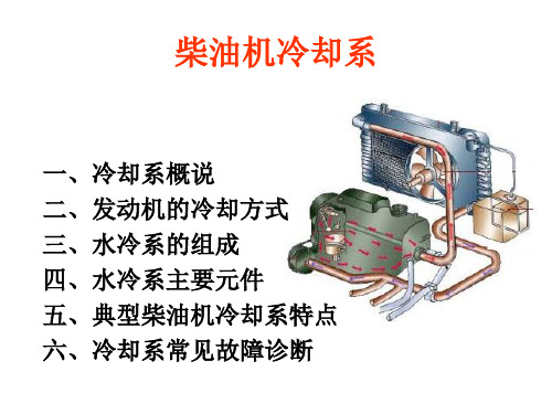
柴油机冷却系
机油冷却器泄漏
检查/更换机油冷却器。检查机油中是 否有冷却液
气缸盖密封垫泄漏
检查/更换气缸盖密封垫
气缸盖开裂或有砂眼
检查/更换气缸盖
气缸体冷却液水套泄漏 检查/更换气缸体
常见故障的排除
9)冷却液污染
故障原因
冷却液不防锈,没有正确混合防 冻剂和水
变速箱机油冷却器(如果装备的 话)泄漏 机油从机油冷却器、气缸盖密封 垫、气缸盖和气缸体中泄漏
✓吸水
与压水 同时,叶轮中 心处压力降低, 散热器中的水 便经进水管被 吸进叶轮中心 部分。
5、风扇
提高流经
散热器的空气 流速和流量, 以增强散热器 的散热能力, 并冷却发动机 附件。
6、节温器
✓关闭位置
影视
6、节温器
✓开启位置
6、节温器
✓外形
7、节温器工作过程动画
五、典型柴油机冷却系特点
散热器顶部水箱或辅助水 检查散热器辅助水箱和顶部水箱之间
箱之间泄漏
是否泄漏
常见故障的排除
6)冷却液温底低于正常温度
故障原因
解决办法
流经散热器的空气过量
依照要求检查/修理百叶窗、风扇离 合器和硅油风扇
节温器断裂、损坏,污染或 密封不良
检查/更换节温器
温度传感器或温度表故障 确定温度传感器或温度表是准确的
1、道依茨柴 油机冷却 系特点
✓外接散热
器式冷却 系
1、道依茨 柴油机冷 却系特点
✓整体式 水冷却系
2、 康 明 斯 发 动 机 冷 却 系 特 点
六、冷却系常见故障诊断
1、常见故障 部位图
✓主要故障是 柴油机过热。
2、常见故障类型
✓冷却液充足但柴油机过热; ✓柴油机突然过热; ✓冷却液消耗异常; ✓冷却液温度过低
柴油机常见故障原因分析

柴油机常见故障原因分析
柴油机是一种内燃机,常见故障的原因可以分为以下几个方面:
1. 燃油问题:燃油供给不足、燃油质量不好等问题都会导致柴油机故障。
燃油供给不足会导致柴油机启动困难,运行不稳定;而燃油质量不好会导致燃油系统堵塞,进一步影响燃油供给。
2. 空气问题:柴油机需要足够的新鲜空气才能进行燃烧,如果空气滤清器堵塞、进气管道漏气等问题会导致燃烧不完全、动力不足等故障。
3. 冷却系统问题:柴油机需要通过冷却系统来降低温度,如果冷却液供应不足、冷却装置堵塞等问题会导致柴油机过热,进而引发一系列故障。
4. 润滑系统问题:柴油机的润滑系统对于发动机的正常运行至关重要。
如果润滑油不足、润滑系统故障等问题会导致摩擦增加,进而造成发动机磨损、故障等。
5. 电气系统问题:柴油机的电气系统包括电池、电动机、线路等。
电池电压低、电动机故障、线路短路等问题会导致柴油机无法启动、启动困难等故障。
6. 排气系统问题:柴油机的排气系统包括排气管、消声器等。
如果排气管漏气、消声器堵塞等问题会导致排气不畅,影响柴油机的功率和燃油消耗。
7. 点火系统问题:柴油机的点火系统包括高压油泵、喷油器等。
如果高压油泵压力不足、喷油器堵塞等问题会导致柴油机无法正常燃烧,引发起动困难等故障。
柴油机常见故障的原因多种多样,但大体可以归结为燃油问题、空气问题、冷却系统问题、润滑系统问题、电气系统问题、排气系统问题和点火系统问题。
了解这些故障的原因,可以帮助我们更好地进行预防和维修,确保柴油机的正常运行和使用寿命。
柴油机冷却系统 ppt课件

3、避免冷却液 耗损,保持水 位不变。
2、冷却系主要零部件构造
35
36
2、冷却系主要零部件构造
37
2、冷却系主要零部件构造
38
3、冷却系的维护及检修
防冻液的正确使用: 防冻液必须干净,并允许在以下范围内使用。 需要注意的是:市售的各著 名品牌的防冻液,多数都是 已经由防冻原液与水按一定 比例配制好的,不能再兑水, 在添加防冻液时必须仔细阅 读外包装上的说明,以确定 是否还需加水稀释。
31
150 100
F 200
C
250
80 40
100 120
温度
来自汽缸头 的冷却液
D12工业用发动机 - 节温器体
150 100
F 200
CLeabharlann 25080 40100 120
温度
来自汽缸头 的冷却液
至散热器
旁通到 循环泵
至循环泵
至循环泵 旁通到
32
循环泵
33
34
五、补液箱
1、把冷却系变 为封闭系统, 避免空气进入 减小氧化腐蚀;
2
1、冷却系的功用和组成
发动机“过冷” 发动机的冷却,如果单纯依靠零件本身对外散热时不够的,必须对某
些零件特别是与高温气体直接接触的零件进行必要的强制冷却,才能保证 发动机正常运转。但是,过分的冷却也将引起不良后果。
a、进入气缸的可燃混和气(或空气)温度太低,使着火困难或燃烧 迟缓,造成发动机功率下降且燃油消耗量增加;
发动机过热或过冷的后果 发动机“过热” a、降低了充气效率,导致发动机的功率下降; b、早燃或爆燃的倾向加大,破坏了发动机的正常工作。同时, 也促使零件承受额外的冲击负荷而造成早期磨损; c、运动件之间的正常间隙被破坏。使零件不能正常运动,甚 至损坏; d、金属材料的机械性能降低,造成零件的变形或损坏; e、润滑状况恶化,加剧了零件的摩擦和磨损。
内燃机车柴油机冷却系统及控制方法

内燃机车柴油机冷却系统及控制方法摘要:冷却系统是机车柴油机充分发挥其大功率的重要保证,一旦其出现问题或故障,柴油机将无法正常运行,甚至危害机车的行车安全,给运输生产带来极大安全隐患。
基于此,本文详细探讨了内燃机车柴油机冷却系统及控制方法。
关键词:内燃机车;柴油机;冷却系统;控制柴油机冷却系统是内燃机车重要部分,对降低油耗和辅助系统功耗、提高运行经济性、改善柴油机排放等意义重大。
受内燃机车总体设备布局、轴重和辅助系统功耗限制,冷却系统的设计要考虑轻质紧凑的散热器,还要考虑高效的冷却方式和控制策略。
一、冷却系统原理冷却系统旨在使柴油机在所有工况下保持在适当温度范围内,防止柴油机过热或过冷。
内燃机车柴油机冷却系统分为高、低温循环水系统,高温循环水系统水经高温水泵加压后,用于冷却气缸套、气缸盖、增压器等部件,进入高温水散热器及燃油预热器、司机室热风机,经由逆止阀回到高温水泵,形成循环;低温循环水系统水经低温水泵加压后,用于冷却中冷器、机油热交换器,冷却机油、静液压油等,进入低温水散热器、静液压油热交换器,经由逆止阀回到低温水泵,形成循环。
柴油机各部件的热量经冷却系统,在冷却间由散热器散热单节将大部分热量传递给空气,保证柴油机等各部件能及时冷却,处在最佳工作温度下。
二、现有内燃机车柴油机冷却系统和控制方法1、冷却系统。
传统东风内燃机车冷却水系统由高低温水泵、中冷器、机油热交换器、散热器、膨胀水箱等构成,冷却气缸套、气缸盖等高温部件系统为高温冷却水系统,冷却机油、增压空气的冷却水系统称为低温冷却水系统,机车冷却系统高低温散热器一般布置在前后,高低温冷却水系统分别由冷却风扇控制。
HXN3内燃机车冷却系统与传统东风内燃机车基本相同,不同处在于采用全封闭加压冷却方式,机油热交换器冷却设置在高温冷却系统中,低温冷却系统仅用于增压空气冷却,所以低温水温不受油温影响。
通过调节高低温冷却风扇电机工作频率,可根据不同排放及油耗要求分别控制高低温水温。
100千瓦柴油发电机组水冷、风冷系统讲解-不同、优缺点讲解
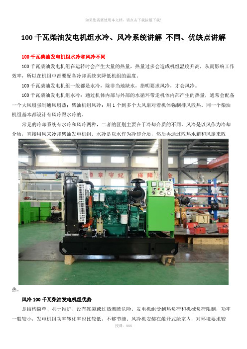
100千瓦柴油发电机组水冷、风冷系统讲解_不同、优缺点讲解100千瓦柴油发电机组水冷和风冷不同100千瓦柴油发电机组在运转时会产生大量的热量,热量过多会造成机组温度升高,从而影响工作效率,所以在机组中都要配备冷却系统来降低机组的温度。
100千瓦柴油发电机组一般都是水冷,除非当地缺水,指明要求风冷,才会风冷。
100千瓦柴油发电机组水冷:通过机体内部与外部的水循环带走机体内部产生的热量,通常会配备一个大风扇强制通风扇热;柴油机组风冷:用1个到多个大风扇对着机体强制排风散热。
同一个柴油机组基本都设计有风冷跟水冷的。
常见的冷却系统有水冷和风冷两种,二者的区别主要在于冷却介质的不同。
风冷是以风作为冷却介质,直接用风来冷却柴油发电机组。
水冷是以水作为冷却介质,然后再通过散热水箱和风扇来散热。
风冷100千瓦柴油发电机组优势是结构简单、利于维护、没有冻裂或过热沸腾危险。
发电机组受到热负荷和机械负荷限制,功率一般较小,发电机组功率转化率也比较低,不够节能。
风冷机安装在敞开式舱室内,对环境要求较高,噪声也较大,需要做机房降噪处理。
风冷方式更多应用在小型汽油发电机、小功率柴油发电机组上。
风冷100千瓦柴油发电机组缺点风冷:用1个到多个大风扇对着机体强制排风散热风冷1.风冷电机安装在敞开式舱室内,噪声较大,冷却效果没水冷好2.风冷比较大的优势就是结构简单、利于维护、故障率低、启动性能好,所需空气量少,风扇消耗功率低,油耗也较低,没有冻裂或过热沸腾危险3.风冷适用于高原或缺水或寒冷的地方,可以不必考虑加水、沸点、冻结等方面的问题,因受到热负荷和机械负荷限制,功率一般都比较小。
风冷机组“道依茨”做的比较好水冷100千瓦柴油发电机组优势冷却效果理想,降温迅速稳定,机组自身的功率转化率高。
水冷机组安装场地局限性小,对环境要求小,噪音低,更可以实现远置式散热系统。
水冷方式一般应用于小型柴油发电机以及大功率柴油发电机组。
现在市场上常见的柴油发电机组品牌康明斯电力、帕金斯、卡特、MTU(奔驰)、沃尔沃和国内的上柴、潍柴一般都是水冷。
柴油机的冷却系统

柴油机的冷却系统柴油机是一种高效、可靠的发动机,其冷却系统对其正常运行至关重要,因为它可以控制发动机的温度,保护发动机的部件免受损坏。
在这篇文章中,我们将探讨柴油机的冷却系统如何工作和保护发动机免受过热的影响。
冷却系统的组成部分柴油机的冷却系统主要由水泵、散热器、水箱、风扇、水管、温控器及冷却液组成。
水泵是冷却系统的主要组成部分之一,它负责循环水流,将冷却液从水箱中抽出,经过发动机散热器后,回到水箱以保持发动机在适宜的温度范围内运转。
散热器是将来自水泵的冷却液传导到发动机中的热量释放出去的设备,它通常由铝制成的排管构成,周围有大量的散热片,具有良好的散热效果。
水箱则负责存储冷却液,同时排放发动机散热器中所产生的热量。
风扇是将冷却空气引入到散热器中的设备,保持散热器周围气流的迅速流动,从而形成较强的冷却效果。
水管则负责将冷却液引导到各个部位,温控器则负责监测发动机温度并控制冷却系统。
冷却液的类型和作用冷却液是发动机冷却系统中的一部分,其作用是保护发动机内部的金属部件免受腐蚀和热量的影响。
冷却液可分为矿物油和有机酸两种类型。
矿物油是传统冷却液,以其稳定、安全、价格低廉等优点受到广泛应用。
然而,由于其缺点是易于与水混合生成沉淀、腐蚀和污染发动机,因此有机酸冷却液的应用也越来越广泛。
有机酸冷却液主要由生物降解的有机酸和添加剂组成,具有良好的防锈防腐、抗冻性能与优异的抗沉淀性能,同时对环境也无任何影响。
为什么冷却系统很重要?柴油机是一种高温、高压的设备,需要冷却系统来保持发动机在适宜的温度范围内运行。
当柴油机达到过热阶段时,机油将变得过于稀薄,失去润滑性,可能会导致引擎损坏。
发动机到达过温阶段的原因有很多,其中包括车辆的过度使用、空气过于污浊、或者是冷却系统发生故障。
这就强调了冷却系统的重要性,因为它有助于保护发动机避免这些潜在的问题。
怎样维护冷却系统?要确保柴油机的冷却系统正常运行,您需要对其进行及时的维修和保养。
- 1、下载文档前请自行甄别文档内容的完整性,平台不提供额外的编辑、内容补充、找答案等附加服务。
- 2、"仅部分预览"的文档,不可在线预览部分如存在完整性等问题,可反馈申请退款(可完整预览的文档不适用该条件!)。
- 3、如文档侵犯您的权益,请联系客服反馈,我们会尽快为您处理(人工客服工作时间:9:00-18:30)。
Analysis and simulation of mobile air conditioning systemcoupled with engine cooling systemZhao-gang Qi *,Jiang-ping Chen,Zhi-jiu ChenInstitute of Refrigeration and Cryogenics,School of Mechanical Engineering,Shanghai Jiao Tong University,No.1954,Huashan Road,Shanghai 200030,PR ChinaReceived 19September 2005;received in revised form 28March 2006;accepted 8October 2006Available online 6December 2006AbstractMany components of the mobile air conditioning system and engine cooling system are closely interrelated and make up the vehicle climate control system.In the present paper,a vehicle climate control system model including air conditioning system and engine cooling system has been proposed under different operational conditions.All the components have been modeled on the basis of experimental data.Based on the commercial software,a computer simulation procedure of the vehicle climate control system has been developed.The performance of the vehicle climate control system is simulated,and the calculational data have good agreement with experimental data.Furthermore,the vehicle climate control simulation results have been compared with an individual air conditioning system and engine cooling system.The influences between the mobile air conditioning system and the engine cooling system are discussed.Ó2006Elsevier Ltd.All rights reserved.Keywords:Air conditioning system;Engine cooling system;Coupled analysis;Simulation;Comparison1.IntroductionA mobile air conditioning (MAC)system can supply drivers and passengers a safe and comfortable environ-ment.Perfect performance of the MAC is the target that automobile manufacturers pursue in the period of design and development.It is known very well that MAC can sup-ply cold capacity under summer operational conditions and waste heat of the engine is used to heat the passenger com-partment under winter operational conditions.For envi-ronmental factors,researches have been performed extensively to develop and improve the efficiencies of MAC and engine cooling systems.Heat exchangers are the research emphasis of MAC and engine cooling systems.A lot of correlations,experiments and models about vari-ous heat exchangers have been proposed.Chang and Wang [1,2]and Chang et al.[3]developed thermal characteristics correlations related to the geometrical parameters of heatexchangers with louvered fins.Their correlations have good agreement with their and previous experimental data in a wide range of Reynolds numbers based on louver pitch.Nowadays,many advanced technologies have been applied to enhance the performance of the heat exchangers of MAC and engine cooling systems.For engineers and researchers,the simulation procedure [4]of MAC and engine cooling systems can save test cost and manpower considerably.Raman Ali [5]developed a computer pro-gram for the MAC refrigerant circuit.The MAC included a condenser and an evaporator cooled by fans,a fixed power reciprocating compressor and a thermostatic expan-sion valve.The heat transfer processes of the condenser and evaporator were divided into three parts as liquid,two phase and gas phase.All the nonlinear algebraic equa-tions were solved by iterative procedures.Saiz Jabardo et al.[6]proposed a steady computer program for an auto-mobile air conditioning system.The authors implied that operational parameters such as compressor speed,return air temperature in the evaporator and condensing air tem-peratures have an obvious effect on the performance of a0196-8904/$-see front matter Ó2006Elsevier Ltd.All rights reserved.doi:10.1016/j.enconman.2006.10.005*Corresponding author.Tel.:+862162933242;fax:+862162632601.E-mail address:qizhaogang@ (Z.-g.Qi)./locate/enconmanEnergy Conversion and Management 48(2007)1176–1184MAC system.Calculational results deviated from the experimentally obtained results within a20%range,though most of them were within a10%range.Lee and Yoo[7] analyzed all the components under various operational conditions and proposed a MAC system model,which sim-ulated the performance of the integrated automobile air conditioning system very well.The component models were dependent on empirical correlations and previous proce-dures.For the engine cooling system,few literatures have been published because of commercial secrets.Bi et al.[8] developed a simulation model of the cooling airflow for armored vehicle engines based on one dimensional tran-sient compressibleflow equations.Many influential factors had been taken into account in the model.In most litera-tures,the MAC and engine cooling systems are studied individually.In fact,many components of the MAC and engine cooling systems are closely interrelated to each other.With any change of vehicle speed,for example,the airflow through the condenser changes,affecting the whole air conditioning system including the vehicle compartment and engine cooling system.To avoid the above mentioned problems,an integrated system of mobile air conditioning system coupled with the engine cooling system,which is called the vehicle cli-mate control system,would be necessary.The targets of this study are to numerically analyze the influences of the engine cooling system on the mobile air conditioning sys-tem and to determine the main operational parameters affecting the vehicle climate control system performance. In the present paper,all the components of the vehicle cli-mate control system are analyzed based on the previous correlations and experimental data.A computer program consisting of the MAC and engine cooling systems is devel-oped to simulate the performance of the vehicle climate control system.2.Analysis of vehicle climate control systemIn the present study,a simulation model of the vehicle climate control system is to be constructed,which consists of a mobile air conditioning system and an engine cooling system.The mobile air conditioning system is mainly com-posed of a laminated evaporator,a parallelflow condenser, afixed displacement reciprocating compressor and an externally equalized thermostatic expansion valve.The engine cooling system is mainly composed of an engine,a serpentine type radiator and a tube in tube oil cooler,as schematically shown in Fig.1.In this vehicle climate con-NomenclatureA area(m2)c1,c2constant(dimensionless)c p specific heat(JkgÀ1KÀ1)f Fanning friction factor,dimensionlessf1,f2,f3correlation defined as Reference[3]F dflow depth(m)h specific enthalpy(J kgÀ1)D h specific enthalpy difference(J kgÀ1)j Colburn factor,dimensionlessL l louver length(m)L p louver pitch(m)g efficiency,dimensionlessd thickness(m)h louver angle,degreee heat exchanger effectiveness,dimensionless Subscriptsad adiabaticair air sidecom compressorcoolant coolant sidedis discharge of compressorffinficfictitious property of saturated air calculated at refrigerant’s temperature_m massflow rate(kg sÀ1)NTU number of transfer units,dimensionlessN compressor speed(rpm)P power(W)D P pressure drop(Pa)Q heat transfer rate(W)Re Lp Reynolds number based on louver pitchT temperature(K)D T temperature difference(K)T d tube width(m)T p tube pitch(m)U overall heat transfer coefficient(W mÀ2kÀ1) fri frictionalgrav gravitationalin inlet/insidelocal locallm mean logarithmic methodmax maximumme mechanicalmin minimummom momentumout outlet/outsideref refrigerant sidesuc suction of compressortot totalV compressor displacement(m3)v volumetricwet wet conditionGreek lettersq density(kg mÀ3)Z.-g.Qi et al./Energy Conversion and Management48(2007)1176–11841177trol system,the operational parameters that can affect the system performance are vehicle speed,air temperature and velocity at the inlet of the condenser and the air tem-perature,humidity and volumetric flow at the inlet of the evaporator.In order to reduce the complexity of the simulation models,the commercial software named KULI is applied to help the authors simulate the vehicle climate control sys-tem.All the models of the components in the vehicle cli-mate control system are proposed based on enormous experimental data.2.1.Heat exchanger model of MAC systemFor calculation of the heat transfer and pressure drop,the evaporator is divided into discrete area elements with their corresponding air and refrigerant mass flows [9,13,14].The changes of the variables of each element can be described by discrete differential equations.The equations are available from two energy balances (air side and refrigerant side).For the dry heat transfer rate of the air side,it is possible to use the following expression [10]:q tot ¼U ÁA ÁD T lm ð1Þwhere D T lm ¼T air ;in ÀT air ;outln T ref ÀT air ;outref air ;inð2Þand U is the global heat transfer coefficient evaluated at the mean properties of the element,which incorporates the influences of the heat transfer coefficients of the air side and refrigerant side and the tube and fin thermal resistances.The air side heat transfer and friction characteristics can be characterized by the j and f factors of a heat exchanger,respectively.The following correlation wassuggested by Chang and Wang [2]and Chang et al.[3]to obtain the air side heat transfer coefficient through the louver fin:j ¼1:18Re À0:505Lph 90 0:26F p L p À0:51T d L p À0:26L l L p0:82ÂT p L p À0:25d f L p À0:097ð3Þf ¼f 1Ãf 2Ãf 3ð4ÞThe correlations of the heat transfer coefficient of the refrigerant side are derived from Refs.[11,12].Because the air is cooled down in the evaporator and condensation can occur,it is necessary that a mass exchange should also be considered.It is based on an anal-ogy of the expression used in dry coils,while for wet coils,the mean logarithmic enthalpy difference is used instead.The heat transfer rate of a wet coil discrete element is given as follows:q wet ;tot ¼_m air ÁD h lm ð5Þwhere D h lm ¼h air ;in Àh air ;out ln h ref ;fic Àh air ;outref ;fic air ;inð6ÞThe pressure drop of the refrigerant side can be expressed in the following equation:D P tot ¼D P fri þD P mom þD P grav þD P localð7Þwhere D P grav =0because the refrigerant flow direction is horizontal.The detailed correlations of D P fri ,D P mom ,and D P local are derived from Ref.[13].The correlations above are the basis of the simulation,and the calculational data will be corrected according to the specific type and geometry of the heat exchanger and the experimentaldata.Fig.1.Mobile air conditioning system coupled with engine cooling system.1178Z.-g.Qi et al./Energy Conversion and Management 48(2007)1176–1184The mathematical model for the condenser is very simi-lar to that of the evaporator.The functions and techniques used in the evaporator are adapted to the condenser.How-ever,the formulas for the inner heat transfer coefficients are quite different.pressor modelThe compressor model is essentially constructed by the characteristics curves.A lot of volumetric efficiency and isentropic efficiency curves were obtained from experi-ments.The massflow rate of refrigerant in the compression process is derived from the following equation:_m ref¼g vÁq sucÁnÁV disð8Þwhere g v is obtained from the characteristic curves of vol-umetric efficiency.The compressor power is obtained fromP com¼_m refÁðh dis;adÀh sucÞgmeð9ÞTo simplify the compressor model,the mechanical effi-ciency of the compressor is described as the following equa-tion based on the tested compressor:gme¼c1þc2lnð_m=_m maxÞð10Þwhere c1=0.8728and c2=0.1777.2.3.Expansion device modelFig.2shows the characteristic curve of the expansion valve.During normal operational conditions,the exter-nally equalized thermostatic expansion valve keeps the superheating degree at the exit of the evaporatorfixed at 5°C.On the basis of an adiabatic throttling,it follows that no change of the enthalpy of the refrigerant takes place in the expansion valve.The massflow equation is drawn from the Bernoulli equation and the adiabatic assumption as follows:_m ref¼A minÁffiffiffiffiffiffiffiffiffiffiffiffiffiffiffiffiffiffiffiffiffiffiffiffiffiffiffiffiffiffiffiffiffi2q minðp inÀp outÞpð11ÞThe analysis algorithms provide at any time that the characteristic curve for the superheat temperature is observed.The pressure drop of the expansion valve is not specially modeled.The pressure drop of the expansion valve results from the equalization process of the MAC circuit.2.4.Engine modelThe engine represents the most important heat source of a vehicle,and therefore,it is essential that the model of the engine should predict the heatflows precisely.The com-plexity of the combustion process as an initial heat source, the heatflows in the engine structure and the heat transfers tofluids and the surrounding air make the set up of this kind of model a very difficult task.In this study,the engine simulation model contains all relevant heat sources and heat transfer areas to calculate the heat impact on the coolant circuit,the oil circuit, and the engine structure(Fig.3)[14].The model contains three heat sources,one for the heatflow related to the coolant circuit,one for the heatflow to the oil circuit and one for the friction.The measurement of the heat flow in the cabin heater can be used to adjust the heat flow to the coolant because the heater will represent the main heat sink as long as the thermostat directs noflow to the radiator.The heatflow of the engine to the cool-ant,depending on engine speed and load,can be inte-grated in the simulation model using a heatflow map based on measured data.Similarly,utilizing the heat transfer data in the engine oil cooler,the heatflow to the oil circuit can be determined.The oil temperature and the oil viscosity are important for calculation of the friction loss.The difference in the heating behavior of the oil and the coolant leads to a var-iable heatflow from the oil to thecoolant.Fig.2.Characteristic curve of externally equalized thermostatic expansion valve.Z.-g.Qi et al./Energy Conversion and Management48(2007)1176–118411792.5.Heat exchangers of engine cooling systemThere is no phase change happening in the heat exchangers used in the engine cooling system.Pressure drops in the radiator and oil cooler are negligible.The models of the two heat exchangers are described using the e-NTU method[15].The heat transfer performance of the heat exchangers is given by the following equation:q¼ð_mc pÞminÁðT coolant;inÀT air;inÞð12Þ2.6.Other modelsOther additional components in the MAC and engine cooling systems are modeled based on the experimental data of the KULI models database[16,17].The effects of connective tubes and receiver dryer in the vehicle climate control system are considered negligible.2.7.Uncertainty analysisThe system model is composed of a number of compo-nents,each of which is modeled on the basis of much experimental data.Each component is modeled individu-ally and compared with the experimental data.These comparable data derive from steady state experiments. The inaccuracy of the component models is shown in Table1.Each component model brings an inaccuracy into the system model.The uncertainty of the predictions of the complete model is estimated by the method sug-gested by Moffat[18].The average uncertainties of the evaporator capacity of the MAC and the coolant temper-ature at the exit of the radiator are6.5%and7.8%at a steady condition,respectively. Fig.3.Engine simulation model.Table1The average inaccuracy of each component at steady condition Components InaccuracyEvaporator 5.2%(evaporator capacity),6.8%(pressure drop) Condenser 4.8%(condenser capacity),7.6%(pressure drop) Compressor7.2%(discharge pressure),10.2%(power) Expansion device 2.0%(quality at the exit of expansion device) Engine9.8%(combustion heat),torque(12.6%) Radiator 5.4%(heat output)Oil cooler9.0%(heat output)Fans 3.8%(volumeflow rate ofair)Fig.4.Schematic diagram of environmental simulation equipment of MAC.Table2Some main components’geometriesComponents Style GeometryEvaporator Laminated125mm·250mm·90mm Condenser Parallelflow600mm·455mm·20mm Compressor Fix displacement Displacement:120(cm3) ExpansionvalveThermostatic expansionvalveSaginomiya1.5ton ofrefrigerationEngine Displacement:1.8L Radiator Serpentine600mm·400mm·30mm Oil cooler Tube in tube60mm·80mm·120mm1180Z.-g.Qi et al./Energy Conversion and Management48(2007)1176–11843.Simulation results and discussion 3.1.Experimental validationIn order to validate the accuracy of the vehicle climate control system simulation models,validation experiments were conducted.Fig.4shows the Environmental Simula-tion Laboratory schematic diagram of the validation exper-iments.Some main components’geometries are shown in Table 2.The amount of superheat at the exit of the evapo-rator is set to 5°C,and the subcooling at the exit of the condenser is fixed at 5°C.The experiments were organized according to the automobile industry standard [19].Fig.5shows the simulation and the experimental condition.The precision of the measured parameters is shown in Table 3.The refrigerant used in the experiments is R-134a.In order for the proposed system to be satisfactory,the capacity to cool the passenger compartment must be offered.In general,the direct measurement of evaporator capacity is very complicated.We often calculate the evap-orator capacity using experimental data.Some errors will be brought into the results.In engineering,the cooling curve is usually used to indicate the satisfactoriness of the system.Fig.6shows the calculational results of the cooling curve compared with the experimental data.During the first 15min,the simulation data have good agreement with the experimental data.After that time,the experimental data is about 2–3°C higher than the calculational data because the ornaments in the passenger compartment have a large heat capacity,which is not reflected in the simula-tion models,and the temperature change will usually respond in a few minutes.It is well established that this dif-ference of experimental and calculational data is acceptable in engineering.The compassion between simulation results and experi-mental data of the coolant temperature at the exit of the radiator is shown in Fig.7.It shows that during all the sim-ulation and experimental conditions,the two results are mostly coincident in a wide test range,and the maximum error is about 5%.The two figures show that the total sim-ulation model of the vehicle climate control system is avail-able in performance analysis,and the calculational results have an adequate accuracy.3.2.Effects of engine cooling system on MACThe simulation results of the individual MAC and MAC coupled with engine cooling system were compared.Fig.8describes the variability of the evaporator capacity in the two different systems.It shows that the evaporator capacity of the vehicle climate control system is lower than that of the individual MAC system because heat from theengineFig.5.Simulation and experimental conditions.Table 3The precision of experimental parameters Items Scale Precision Vehicle speed 0–200(km h À1)±0.1(km h À1)Environmental temperature À30°C to 60°C ±1(°C)Relative humidity 15–95%±5%Sunlight power0–1100(W m À2)The fluctuation of the temperatureon the top of vehicle is ±3(°C)Air velocity0–140(km h À1)±0.5(km h À1)Thermocouple (K type)±0.1(°C)Pressure transducer0–18(bar)±0.1(bar)parison of cooling curve vs.test time.Z.-g.Qi et al./Energy Conversion and Management 48(2007)1176–11841181compartment is conducted to the passenger compartment through the vehicle body,which increases the heat duty.Fig.9shows the variability of power consumption of the compressor in the two different systems.It presents that compressor power of the vehicle climate control system is greater than that in the individual MAC during the whole simulation period.It is considered that the engine opera-tional status in the engine cooling system influences the compressor operation via the viscous clutch.These phe-nomena are particularly obvious during the low speed,gra-dient and idle status.Fig.10shows the effect of the engine cooling system on the coefficient of performance (COP)of the mobile air con-ditioning system.The engine cooling system results in the COP of the mobile air conditioning system being decreasedclearly during the entire simulation time,especially during the low vehicle speed and idle status.The maximum decrease of COP is up to 10%.It is considered to be due to the decrease of evaporator capacity and the increase of the compressor work simultaneously during a wide opera-tional conditioning range.The effect of vehicle speed on the performance of the mobile air conditioning system is shown Fig.11.When the vehicle speed is changed from 20km/h to 40km/h,the cooling capacity increases up to 13%,and the compres-sor power increases up to 23%at the same time,but the COP of the MAC decreases sharply.It is considered to be due to the fact that the rate of increase in the compres-sor power becomes larger than the rate of increase in the evaporator capacity.The evaporator capacity will keep steady as the vehicle speed is higher than 40km/h.Inotherparison of COP (individual MAC and MAC coupled with engine coolingsystem).parison of coolant temperature at the exit of radiator vs.testtime.parison of evaporator capacity (individual MAC and MAC coupled with engine coolingsystem).parison of compressor power (individual MAC and MAC coupled with engine cooling system).1182Z.-g.Qi et al./Energy Conversion and Management 48(2007)1176–1184words,the mobile air conditioning system can maintain a better cooling performance in a wide vehicle speed range.3.3.Effect of MAC on the engine cooling systemFig.12shows the comparison of the heat output of the radiator between the vehicle climate control system and the individual MAC.The heat output of the radiator is higher than that of the individual MAC system throughout the whole simulation time.It is the result of the exit air temper-ature of the condenser being higher than the environmental air temperature,which decreases the temperature differenceof heat transfer on the air side of the radiator.The maxi-mum difference in heat output of the radiator between the two different systems is about 3kW.Fig.13shows the effect of air temperature at the exit of the condenser on the heat output of the radiator at the vehicle speed of 120km/h.It shows that the heat output of the radiator decreases with the increase of the exit air temperature of the condenser.At the worst condition,the heat output of the radiator decreases about 1.5kW.Fig.14shows the effect of air temperature at the exit of the condenser on the temperatures of the coolant,oilFig.11.Effect of vehicle speed on the performance of air conditioningsystem.parison of heat output of radiator (individual MAC and MAC coupled with coolingsystem).Fig.13.Effect of air temperature at the exit of condenser on the heat output of radiator.Z.-g.Qi et al./Energy Conversion and Management 48(2007)1176–11841183and air in the engine cooling system at the vehicle speed of 120km/h.Most temperatures in the engine cooling system will increase with the increase of air temperature at the exit of the condenser.The coolant temperature at the exit of the radiator reaches 102°C when the air tem-perature at the exit of the condenser is higher than the environmental temperature up to 11–14°C,which exceeds the temperature within which the engine can work normally.This condition should be avoided in the design period and improvement process of the mobile air conditioning system and engine cooling system.4.ConclusionsBased on commercial software,a simulation model of the mobile air conditioning system coupled with the engine cooling system is developed.The vehicle climate control system mainly contains a laminated evaporator,a parallel flow condenser,a fixed displacement reciprocat-ing compressor,an externally equalized thermostatic expansion valve,an engine,a serpentine type radiator and a tube in tube oil cooler.The models of the compo-nents are based on great amounts of experimental data.Then,validation experiments are performed at the envi-ronmental simulation laboratory,and the experimental results are compared with the simulation results.The comparative results show that the simulation model of the vehicle climate control system is available in engineer-ing and has a good accuracy.The following conclusions are drawn from the perfor-mance simulation and analysis of the vehicle climate con-trol system:1.The engine cooling system affects the performance of the mobile air conditioning system considerably.The simu-lation results show the engine cooling system results in the COP of the mobile air conditioning system decreas-ing clearly during the entire simulation time,especially during the low vehicle speed and idle status.The maxi-mum decrease of COP is up to 10%.2.Changes of heat duty of the mobile air conditioning sys-tem result in high air temperature at the exit of the con-denser,reducing the driving potential for heat transfer from the coolant to air,which induces the heat output of the radiator to decrease sharply.The maximum differ-ence of heat output of the radiator between the engine cooling systems and the vehicle climate control system is about 3kW.References[1]Chang YJ,Wang CC.Air side performance of brazed aluminum heat exchangers.J Enhanc Heat Transf 1996;3:15–28.[2]Chang YJ,Wang CC.A generalized heat transfer correlation for louver fin geometry.Int J Heat Mass Transfer 1997;40:533–44.[3]Chang et al.A generalized friction correlation for louver fin geometry.Int J Heat Mass Tran 2000;43:2237–43.[4]Hamilton JF,Miller JL.A simulation program for modeling an air-conditioning system.ASHRAE Trans 1990;96(Part 1):213–21.[5]Raman Ali A.Modeling of condensers,evaporators and refrigeration circuit in automobile air conditioning systems.PhD thesis.University of Valladolid,Valladolid,Spain;1995[in Spanish].[6]Saiz Jabardo JM,Gonzales Mamani W,Ianella MR.Modeling and experimental evaluation of an automotive air conditioning system with a variable capacity compressor.Int J Refrig 2002;25:1157–72.[7]Lee GH,Yoo JY.Performance analysis and simulation of automobile air conditioning system.Int J Refrig 2000;23:243–54.[8]Bi Xiaoping et al.A simulation model of cooling air flow for armored vehicle engines.Trans SCICE 2002;20(4):373–6[in Chinese].[9]Thomas Anzenberger,Roland Marzy,Josef Hager.Simulation of air conditioning circuit in vehicles under consideration of the engine cooling system.In:ISATA 2000automotive and transportation congress,Dublin,Ireland.Paper No.00SVR006.[10]Corbera´n Jose ´M,Melo ´n Mo ´nica Garcı´a.Modelling of plate finned tube evaporators and condensers working with R134a.Int J Refrig 1998;21(4):273–84.[11]Gnielinski V.New equations for heat and mass transfer in turbulentpipe and channel flow.Int Chem Eng 1976;16:360–8.[12]Dobson MK,Chato JC.Condensation in smooth horizontal tubes.JHeat Transf 1998;120:193–213.[13]Zhang Ming,Webb Ralph L.Correlation of two-phase friction forrefrigerants in small-diameter tubes.Exp Therm Fluid Sci 2001;25:131–9.[14]Roland Marzy,Josef Hager,Clemens Doppelbauer.Optimization ofvehicle warm-up using simulation tools.In:VTMS5conference.Nashville (TN),USA;2001.[15]Kays WM,London pact heat exchangers.3rd ed.NewYork:McGraw-Hill Book Company;1984.[16]KULI V6.4manual-HVAC.Engineering Center Styer.[17]KULI V6.4manual-engine theory.Engineering Center Styer.[18]Moffat RJ.Describing the uncertainties in experimental results.ExpTherm Fluid Sci 1988;1:3–17.[19]QC/T 658-2000.Automobile industry standard of People’s Republicof China.Beijing:National Bureau of Mechanical Industry;2001[inChinese].Fig.14.Effect of air temperature at the exit of condenser on the temperature of coolant,oil and air.1184Z.-g.Qi et al./Energy Conversion and Management 48(2007)1176–1184。