PC LUPOY GP-2401F
YF2401用户手册V1.24
YF2401荧光灯通用集成基准源用户手册YF2401FLUORESCENT LAMPINTEGRATED HIGH FREQUENCYSTANDARD SOURCEUSER’S MANUALVer 1.24杭州远方光电信息有限公司EVERFINE PHOTO-E-INFO CO., LTD.地址:中国杭州市滨江区滨康路669号(310053)ADD:No.669 Binkang Rd., Binjiang Hi-Tech Zone, Hangzhou(310053), ChinaTel :86-571-86698333Fax :86-571-86696433E-mail:Sales@销售专箱Service@服务专箱http://前言感谢购置远方光电YF2401荧光灯通用集成基准源。
本用户手册包含仪器功能和操作过程等,为了确保正确使用仪器,在操作仪器前请仔细阅读本手册。
请妥善保存本手册,以便碰到问题时快速查阅。
注意:∙手册内容有可能改变,恕不另行通知。
∙我们已经尽最大努力准备本手册以确保其准确性,然而,如您有疑问或发现错误,请直接与本公司或本公司授权代理商联系。
∙没有本公司书面许可,任何抄袭或改编本手册全部或部分内容均为严重侵权。
∙对于手册内容如有不同理解,以本公司技术部门解释为准。
检查装箱清单用户第一次打开包装箱时,请检查装箱清单。
若发现仪器或配件错误,配件不齐或不正常,请与制造商或代理商联系。
目录第一章概述 (3)第二章特别警示 (4)第三章基本原理 (5)第四章技术指标 (6)第五章面板说明 (7)5.1前面板说明 (7)5.2 后面板说明 (10)第六章操作步骤 (11)第七章软件使用说明 (15)第八章注意事项 (25)第九章测试报告示例 (25)附录快速操作指南 (34)第一章概述YF2401荧光灯通用集成基准源 (英文名称Fluorescent Lamp Integrated High Frequency Standard Source,以下简称电源),是一种开路电压可调的纯正弦高频基准电源。
Skyworks Solutions RFX2401C数据手册说明书
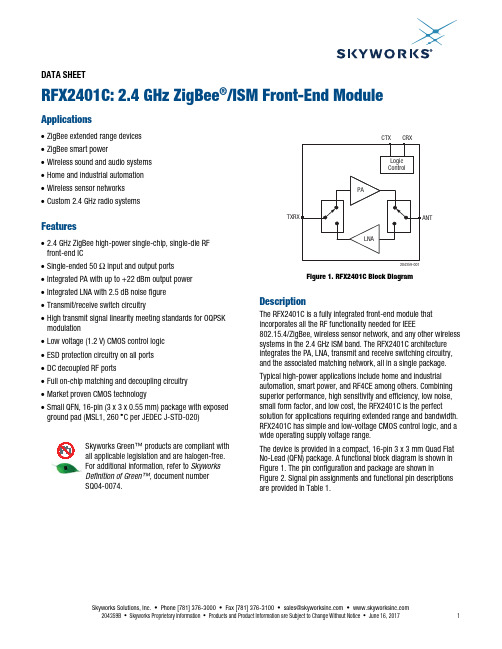
DATA SHEETRFX2401C: 2.4 GHz ZigBee ®/ISM Front-End ModuleApplications∙ ZigBee extended range devices ∙ ZigBee smart power∙ Wireless sound and audio systems ∙ Home and industrial automation ∙ Wireless sensor networks ∙ Custom 2.4 GHz radio systemsFeatures∙ 2.4 GHz ZigBee high-power single-chip, single-die RF front-end IC∙ Single-ended 50 Ω input and output ports ∙ Integrated PA with up to +22 dBm output power ∙ Integrated LNA with 2.5 dB noise figure ∙ Transmit/receive switch circuitry∙ High transmit signal linearity meeting standards for OQPSK modulation∙ Low voltage (1.2 V) CMOS control logic ∙ ESD protection circuitry on all ports ∙ DC decoupled RF ports∙ Full on-chip matching and decoupling circuitry ∙ Market proven CMOS technology∙ Small QFN, 16-pin (3 x 3 x 0.55 mm) package with exposed ground pad (MSL1, 260 ︒C per JEDEC J-STD-020)S kywork s G reen™ product s are compliant with all applicable legi s lation and are halogen-free.For additional information, refer to Skyworks Definition of Green™, document number S Q04-0074.204359-001Figure 1. RFX2401C Block DiagramDescriptionThe RFX2401C is a fully integrated front-end module that incorporates all the RF functionality needed for IEEE802.15.4/ZigBee, wireless sensor network, and any other wireless systems in the 2.4 GHz ISM band. The RFX2401C architecture integrates the PA, LNA, transmit and receive switching circuitry, and the associated matching network, all in a single package. Typical high-power applications include home and industrial automation, smart power, and RF4CE among others. Combining superior performance, high sensitivity and efficiency, low noise, small form factor, and low cost, the RFX2401C is the perfect solution for applications requiring extended range and bandwidth. RFX2401C has simple and low-voltage CMOS control logic, and a wide operating supply voltage range.The device is provided in a compact, 16-pin 3 x 3 mm Quad Flat No-Lead (QFN) package. A functional block diagram is shown in Figure 1. The pin configuration and package are shown inFigure 2. Signal pin assignments and functional pin descriptions are provided in Table 1.204359-002N/C G ND G ND TXRX TXENN/CVDD N/CG ND ANTG NDRXENN/C DN C VDD G ND1651234151413678910111217G NDFigure 2. RFX2401C Pinout(Top View)Table 1. RFX2401C Signal DescriptionsPin Name DescriptionPin Name Description1 N/C Not connected internally 9 GND Ground2GNDGround 10ANTConnect to 50 Ω antenna (DC shorted to GND) 3 GND Ground11 GND Ground4 TXRX RF signal to/from the transceiver (DC shorted to GND) 12 N/C Not connected internally5 TXEN CMOS input to control TX enable 13 DNC Do not connect6 RXEN CMOS input to control RX enable 14 VDD Alternate supply pin, internally connected to pin 167 N/C Not connected internally 15 N/C Not connected internally 8GNDGround16VDDVoltage supply connectionElectrical and Mechanical SpecificationsThe absolute maximum ratings of the RFX2401C are provided in Table 2. The recommended operating conditions are specified in Table 3. The electrical specifications are provided in Tables 4 and 5. The state of the RFX2401C is determined by the logic provided in Table 6.Table 2. RFX2401C Absolute Maximum Ratings1Parameter Conditions Minimum Maximum Units DC VDD voltage supply 0 4.0 VDC control pin voltage Through 1 kΩ resistor 0 3.6 VDC VDD current consumption Through VDD pins when TX is “ON” 350 mADC control pin current consumption 1 μATX RF input power All operating modes +5 dBmANT RF input power When RX is “ON” +5 dBmJunction temperature 150 °CStorage ambient temperature No RF and DC voltages applied -50 +150 o CElectrostatic discharge:Human Body Model (HBM) 3250 V 1Exposure to maximum rating conditions for extended periods may reduce device reliability. There is no damage to device with only one parameter set at the limit and all other parameters set at or below their nominal value. Exceeding any of the limits listed here may result in permanent damage to the device. All maximum RF input power ratings assume 50 Ω terminalimpedance.ESD HANDLING: Although this device is designed to be as robust as possible, electrostatic discharge (ESD) can damage this device.This device must be protected at all times from ESD when handling or transporting. Static charges may easily producepotentials of several kilovolts on the human body or equipment, which can discharge without detection.Industry-standard ESD handling precautions should be used at all times.Table 3. RFX2401C Recommended Operating Conditions1Parameter Conditions Min Typ Max Units DC VDD voltage supply All VDD pins 2.0 3.3 3.6 VControl voltage “high” Through 1 kΩ resistor 1.2 VDD VControl voltage “low” 0 0.3 VOperating ambient temperature Note 2 -40 +125o Cθja35o C/W1 During production test, devices will be tested at 5 V.2 For operation above +85 °C, use the θ ja as guidance for system design to assure the junction temperature will not exceed the maximum of +150 °C.Table 4. RFX2401C Electrical Specifications1 (V DD = 3.3 V, All Unused Ports Terminated with 50 Ω, T A = 25 °C, Unless Otherwise Noted) Parameter Symbol Test Condition Min Typ Max Units Frequency range f 2.4 2.525 GHz Transmit ModeSaturated output power +22 dBm Small-signalgain 21.5 25 26.5 dBSecond harmonic P OUT = +20 dBm, IEEE 802.15.4OQPSK modulation signal–10 dBm/MHzThird harmonic P OUT = +20 dBm, IEEE 802.15.4OQPSK modulation signal–20 dBm/MHzInput return loss –10 dBOutputreturnloss –6 dB Input / output impedance single-ended 50 ΩTX quiescent current No RF applied 17 mATX high-power current P OUT = +20 dBm 90 mALoad VSWR for stability (P OUT = +20 dBm) All non-harmonically related spursless than –43 dBm/MHz6:1 N/ALoad VSWR for ruggedness(P OUT = +20 dBm)No damage 10:1 N/A Receive ModeGain 12 dB Noisefigure 2.5 dB Input return loss –10 dBOutput return loss –12 dBRf port impedance 50 ΩRx quiescent current No RF applied 8 mAInput p1db At ANT pin –8 dBm1 Performance is guaranteed only under the conditions listed in this table.Table 5. RFX2401C Standby Mode Technical ParametersParameter Symbol Test Condition Min Typ Max Units DC shutdown current 1 μATXRX-ANT insertion loss (S21) Pin < -20 dBm –50 dBANT-TXRX insertion loss (S21) –50 dBReturn loss (S11) From TXRX port –1.5 dBTransmit-receive switchingtime 800 nsec Shutdown and “ON” State switchingtime 800 nsecTable 6. RFX2401C Control Logic1Mode TXEN RXENTX active 1 xRX active 0 1Shutdown 00 1 “1” denotes high voltage state (> 1.2 V)“0” denotes low voltage stage (< 0.3 V) at control pins“X” denotes do not care: either “1” or “0” can be appliedApplication Schematic Board DescriptionA suggested RFX2401C FEM application schematic diagram is shown in Figure 3. A schematic of the Evaluation Board is shown in Figure 4.Circuit Design ConsiderationsThe following design considerations are general in nature and must be followed regardless of final use or configuration:∙Paths to ground should be made as short as possible.∙If the transceiver TXRX port has DC present, use a capacitor to block this voltage from reaching the RFX2401C.∙The ground pad of the RFX2401C has special electrical and thermal grounding requirements. This pad is the main thermal conduit for heat dissipation. Because the circuit board acts as the heat sink, it must shunt as much heat as possible from the device.Multiple vias to the grounding layer are e thermal vias to assure efficient heat dissipation. ∙Locate the bypass capacitors as close as possible to the ground pad. Use two ground vias.∙The VDD (pin 14) is an optional VDD pin, internally connected to pin 16.∙The N/C pins 1, 7, 12, and 15 may be left open or connected to GND.∙If the antenna circuits have DC present, use a capacitor to block this voltage from reaching the RFX2401C.NOTE: A poor connection between the ground pad and ground increases junction temperature (T J), which reduces the lifeof the device..J4Figure 3. RFX2401C Application SchematicMA J2SFigure 4. RFX2401C Evaluation Board SchematicPackage DimensionsThe PCB layout footprint for the RFX2401C is shown in Figure 5. Typical part markings are shown in Figure 6. Package dimensions are shown in Figure 7, and tape and reel dimensions are provided in Figure 8.Package and Handling InformationInstructions on the shipping container label regarding exposure to moisture after the container seal is broken must be followed. Otherwise, problems related to moisture absorption may occur when the part is subjected to high temperature during solder assembly.The RFX2401C is rated to Moisture Sensitivity Level 1 (MSL1) at 260 C. It can be used for lead or lead-free soldering. For additional information, refer to the Skyworks Application Note, Solder Reflow Information , document number 200164. Care must be taken when attaching this product, whether it is done manually or in a production solder reflow environment. Production quantities of this product are shipped in a standard tape and reel format.204359-0040.5mm0.25mmFigure 5. RFX2401C PCB Layout Footprint(Top View)204359-006S kywork s Part Number Lot C odeDate C odePin 1Figure 6. Typical Part Markings(Top View)9-007Figure 7. RFX2401C Package DimensionsAll measurements are in millimeters.204359-0083.30 ±0.10Figure 8. RFX2401C Tape and Reel DimensionsDATA SHEET • RFX2401C: 2.4 GHz ZIGBEE/ISM FRONT-END MODULEOrdering InformationModel Name Manufacturing Part Number Evaluation Board Part Number RFX2401C: 2.4 GHz ZigBee/ISM Front-End Module RFX2401C RFX2401C-EK1Copyright © 2016-2017 Skyworks Solutions, Inc. All Rights Reserved.Information in this document is provided in connection with Skyworks Solutions, Inc. (“Skyworks”) products or services. These materials, including the information contained herein, are provided by Skyworks as a service to its customers and may be used for informational purposes only by the customer. Skyworks assumes no responsibility for errors or omissions in these materials or the information contained herein. Skyworks may change its documentation, products, services, specifications or product descriptions at any time, without notice. Skyworks makes no commitment to update the materials or information and shall have no responsibility whatsoever for conflicts, incompatibilities, or other difficulties arising from any future changes.No license, whether express, implied, by estoppel or otherwise, is granted to any intellectual property rights by this document. Skyworks assumes no liability for any materials, products or information provided hereunder, including the sale, distribution, reproduction or use of Skyworks products, information or materials, except as may be provided in Skyworks Terms and Conditions of Sale.THE MATERIALS, PRODUCTS AND INFORMATION ARE PROVIDED “AS IS” WITHOUT WARRANTY OF ANY KIND, WHETHER EXPRESS, IMPLIED, STATUTORY, OR OTHERWISE, INCLUDING FITNESS FOR A PARTICULAR PURPOSE OR USE, MERCHANTABILITY, PERFORMANCE, QUALITY OR NON-INFRINGEMENT OF ANY INTELLECTUAL PROPERTY RIGHT; ALL SUCH WARRANTIES ARE HEREBY EXPRESSLY DISCLAIMED. SKYWORKS DOES NOT WARRANT THE ACCURACY OR COMPLETENESS OF THE INFORMATION, TEXT, GRAPHICS OR OTHER ITEMS CONTAINED WITHIN THESE MATERIALS. SKYWORKS SHALL NOT BE LIABLE FOR ANY DAMAGES, INCLUDING BUT NOT LIMITED TO ANY SPECIAL, INDIRECT, INCIDENTAL, STATUTORY, OR CONSEQUENTIAL DAMAGES, INCLUDING WITHOUT LIMITATION, LOST REVENUES OR LOST PROFITS THAT MAY RESULT FROM THE USE OF THE MATERIALS OR INFORMATION, WHETHER OR NOT THE RECIPIENT OF MATERIALS HAS BEEN ADVISED OF THE POSSIBILITY OF SUCH DAMAGE.Skyworks products are not intended for use in medical, lifesaving or life-sustaining applications, or other equipment in which the failure of the Skyworks products could lead to personal injury, death, physical or environmental damage. Skyworks customers using or selling Skyworks products for use in such applications do so at their own risk and agree to fully indemnify Skyworks for any damages resulting from such improper use or sale.Customers are responsible for their products and applications using Skyworks products, which may deviate from published specifications as a result of design defects, errors, or operation of products outside of published parameters or design specifications. Customers should include design and operating safeguards to minimize these and other risks. Skyworks assumes no liability for applications assistance, customer product design, or damage to any equipment resulting from the use of Skyworks products outside of stated published specifications or parameters.Skyworks and the Skyworks symbol are trademarks or registered trademarks of Skyworks Solutions, Inc., in the United States and other countries. Third-party brands and names are for identification purposes only, and are the property of their respective owners. Additional information, including relevant terms and conditions, posted at , are incorporated by reference.SkyworksSolutions,Inc.•Phone[781]376-3000•Fax[781]376-3100•*********************•204359B • Skyworks Proprietary Information • Products and Product Information are Subject to Change Without Notice • June 16, 2017 11Mouser ElectronicsAuthorized DistributorClick to View Pricing, Inventory, Delivery & Lifecycle Information:S kyworks:RFX2401C RFX2401C-EK1。
西门子 SINAMICS G120 变频器 说明书
调试,保证了组态的简单和调试的方便 — 由于 Drive ES Basic STARTER 集成在 STEP 7中,这就保证了数据的集中保存和通信 的连续性 ● 符合世界范围的认证: CE,UL,cUL,c-tick 以及集成的安全保护 标准 IEC 61508 S
选型订货数据
3
PM240
概述
功率模块
电气连接
技术参数
选型订货数据
4
特性曲线
安装尺寸
PM250
概述
功率模块
电气连接
技术参数
选型订货数据
5
特性曲线
安装尺寸
选件
进线侧功率部件
直流母线功率部件
输出侧功率部件 其它系统选件
6
SINAMICS G120 产品样本
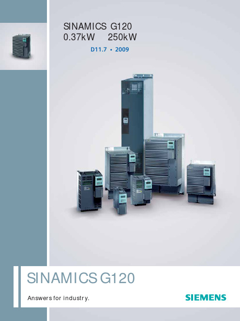
SINAMICS G120
变频器0.37kW至250kW
设计
SINAMICS G120 为标准传动中按照模块化设计的变频器系列。每个 SINAMICS G120 变频器都由功率模块和控制单元两个必要单元组成。
功率模块 SINAMICS G120 有以下可选的功率模块作为变频器基本单元:
PM240 功率模块 PM240 功率模块是按照不进行再生能量回馈设计的,它的特点是 都带有内置的制动斩波器。制动中产生的再生能量通过外接的制 动电阻转化为热能进行消耗。
设备和工厂 ● 提供更强大的支持PROFIdrive Profil 4.0 的PROFIBUS 通讯 -减少了接口数量 -全厂范围内组态 -操作更加简单 ● 创新的冷却理念和加涂层的电子模块加强了环境适应能力 ● 设备更换更加简单,通过基本操作面板和MMC卡进行参数克隆
ABB双电源产品技术选型手册

的自动转换时,可选择 DPT-CB011(标配消防切非)为动力 来进行各种控制操作,OTM_C 电动型双电源可与其控制器形
负荷提供可靠电源,确保供电可靠性和连续性。
成完美的配合,非常适用于柴发的应用。
1
DPT250-CB011 R250 4 P
柴油发电机的控制箱: OTM_C和控制器配 合用于切换电源
OTM_E_C OTM32...125F_C_10 / 11D
OTM_E_C_10D / 11D
OTM_C_D 双电源自动转换开关 - 额定电流可高达 2500A - 配备 10D、11D、3D 或 8D 控制器 - 具有隔离功能 - 开关断口可见,开关状态一目了然 - 可短时承受过载及短路电流 - 可带负载切换 - 可靠的机械及电气联锁,确保用电安全 - 可手动、电动及自动操作 - 专利设计的内置离合器,使手动操作更轻松 - 开关具有 3 个稳定的位置:I-O-II - 单相检测 - 10D / 11D 控制器具有 N 线接错报警及保护功能 - 3D / 8D 控制器设有频率检测功能 - 8D 控制器设有通讯及故障记忆功能
系列号 OT_C:PC 级双电源手动转换开关
OTM 250 E 3 C M 230 C
电源种类 C:交流
操作机构工作电压 220、230、380
控制方式 M:按钮操作 D :控制器自动操作
(10D、11D、3D、8D)
ห้องสมุดไป่ตู้
开关类型 C:转换开关
极数 3 极、4 极
符合的标准 E:符合 IEC 标准 F:符合 IEC 标准
(仅适用于 125A 以下)
电流等级
32、40、50、63、80、100、125、 160、200、250、315、400、630、 800、1000、1250、1600、2000、 2500
PCF系列单段锤式破碎机1
前言为了更好地发挥单段锤式破碎机的功能和效率,确保其正常工作,在安装该设备之前和使用过程中,请仔细参阅本说明书的内容,这将有助于为用户熟悉维护设备提供方便。
一、概述:单段锤式破碎机用于破碎一般性的脆性矿石,如石灰石、泥质粉砂岩、页岩、石膏和煤等,也适合破碎石灰石和粘土质的混合物。
本机特点破碎比大,可将大块原矿石一次破碎到符合入磨粒度,与传统的两段破碎系统相比,可节省一次性投资45%,车间设备重量减轻32.5%,矿石破碎成本降低约40%。
操作简单,维修方便,改善了工人的劳动强度。
因此只要矿石的物理性质适合,选用本机作为大型矿山的碎矿设备是比较经济可靠的方案。
本机作为水泥厂主要的破碎设备,与同类单转子单段破碎设备相比,更适合雨量较大,料湿,含土较多的工作状况。
由于本机具有特殊的结构,使得破碎较粘物料时消除了堵塞沾附之患,并具有特殊的双重过铁保护装置,可将不慎混入机内的铲齿,钻头,铁锤等金属异物自动反弹回给料辊或排出机外,不必为此停机,工作安全可靠。
本机备有两个同向异速给料辊向破碎机转子进行全宽度喂料,减轻了矿石对转子不必要的负载和冲击,使得转子运转更为平稳因而转子负荷平稳。
电耗低,锤头、篦子等易损件寿命长、技术经济指标优于国内外同型机。
二.产品技术参数(1)主要规格和性能注:特殊机型以合同为准,具体技术参数见合同(2)主要部件的重量(3)给料辊主要技术参数PCF-2018(K3909),PCF-2022(K3905B,K3905C)电动机功率(KW):45电动机电压(V):380电动机转速(r/min):980减速比:皮带轮:1.32 减速机:45主动辊转速(r/min):18.25从动辊转速(r/min):14.5破碎机的出料粒度可以根据用户的要求设计,其最大出料粒度可放宽到≤100㎜,生产能力和所需功率取决于矿石的物理性质和进、出料粒度。
因此,用户在定货之前应提出与此有关的技术条件和矿石样品,以便进行必要的原料加工实验,取得数据后作出有针对性的设计和确定装机功率。
中国电信4G泛智能终端白皮书(2020.V1版)2020-01-17

业务功能
4GFZN-11201[必选]通话业务要求
如下是对终端的要求:
1)终端应必选支持语音主被叫、紧急呼叫、语音消息、上课禁用、屏蔽陌生号码等功能;
2)终端推荐支持录音功能、智能语音人机交互、与即时通信(IM)工具的交互等功能;
3)其中紧急呼叫、上课禁用、屏蔽陌生号码功能的开启/关闭及设置管理只能通过绑定手机上的APP进行操作;
1)终端应支持以下:
编号
制式要求
频段要求(注)
协议版本要求
1.
FDD(必选)
必选频段:B1、B3、B5
3GPP R9或以上协议版本,至少Category1,推荐Category4及以上
2.
TDD(必选)
必选频段:B41
3GPP R9或以上协议版本,至少Category1,推荐Category4及以上
4)终端推荐支持室内定位,包括商场、火车站、机场等人多的室内环境;
5)终端必选支持与儿童手表绑定的终端实现位置查询、轨迹记录、电子围栏、位置短信等功能,其中轨迹记录功能默认为开启状态。
配置
4GFZN-11301[必选]手表与手机交互要求
如下是对终端的要求:
1)应支持手机绑定功能;
2)儿童手表与终端的恢复功能(包括解除当前绑定、重新设置绑定、恢复出厂设置),应从当前绑定手机的APP中发起,并需要通过当前绑定手机的确认和授权,在完成儿童手表、当前绑定终端及APP、平台之间的数据同步、备份和保存后,可执行恢复操作。儿童手表本身不能发起恢复操作。
4GFZN-11302[必选]配置与升级要求
如下是对终端的要求:
1)儿童手表设置菜单支持软硬件版本信息查询;
2)终端应支持新版本软件升级功能,该升级应通过绑定手机APP端进行授权许可;
无线模块2401调试方法(C51)
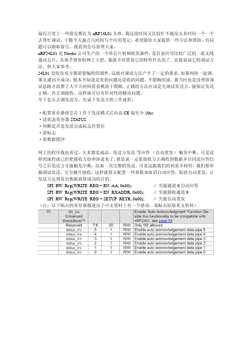
//*************************************SPI(nRF24L01)寄存器地址**************************************************** #define CONFIG #define EN_AA #define EN_RXADDR #define SETUP_AW #define SETUP_RETR #define RF_CH #define RF_SETUP #define STATUS #define OBSERVE_TX #define CD #define RX_ADDR_P0 #define RX_ADDR_P1 #define RX_ADDR_P2 #define RX_ADDR_P3 #define RX_ADDR_P4 #define RX_ADDR_P5 #define TX_ADDR #define RX_PW_P0 #define RX_PW_P1 #define RX_PW_P2 #define RX_PW_P3 #define RX_PW_P4 #define RX_PW_P5 #define FIFO_STATUS 0x00 0x01 0x02 0x03 0x04 0x05 0x06 0x07 0x08 0x09 0x0A 0x0B 0x0C 0x0D 0x0E 0x0F 0x10 0x11 0x12 0x13 0x14 0x15 0x16 0x17 // 配置收发状态,CRC 校验模式以及收发状态响应方式 // 自动应答功能设置 // 可用信道设置 // 收发地址宽度设置 // 自动重发功能设置 // 工作频率设置 // 发射速率、功耗功能设置 // 状态寄存器 // 发送监测功能 // 地址检测 // 频道 0 接收数据地址 // 频道 1 接收数据地址 // 频道 2 接收数据地址 // 频道 3 接收数据地址 // 频道 4 接收数据地址 // 频道 5 接收数据地址 // 发送地址寄存器 // 接收频道 0 接收数据长度 // 接收频道 0 接收数据长度 // 接收频道 0 接收数据长度 // 接收频道 0 接收数据长度 // 接收频道 0 接收数据长度 // 接收频道 0 接收数据长度 // FIFO 栈入栈出状态寄存器设置
Philips AX2400 AX2401 AX2420 可移动CD播放器用户手册说明书
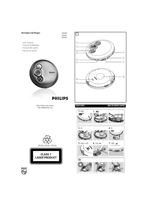
QUICK STARTMISE EN SERVICE RAPIDEMeet Philips at the Internet user manualmanuel d’utilisation manual del usarioManual do usuárioAX2400, AX2401,AX2420Portable CD PlayerAX2400AX2401AX2420EnglishCONTROLS / POWER SUPPLY12;......................switches the player on, starts or pauses CD play 2............................display39.........................stops CD play, clears a program or switches the player off ∞.......................skips and searches CD tracks backwards §.......................skips and searches CD tracks forwards4DBB.....................switches the bass enhancement on and off. This button alsoswitches acoustic feedback (the beep) on/off when it is pressed for more than 2 seconds5PROG...................programs tracks and reviews the program6MODE/ESP..........selects the different playing possibilities: SHUFFLE ,SHUFFLE REPEAT ALL , REPEAT , REPEAT ALL and SCAN ,switch ESP on/off7VOLUME +/-......adjust the volume8p /LINE OUT........3.5 mm headphone socket, socket to connect the player toanother audio input of an additional appliance.9OPEN ç............opens the CD lid 0HOLD...................locks all buttonsRESUME.............stores the last position of a CD track played OFF......................switches RESUME and HOLD off !4.5V DC...............socket for external power supply @............................type platePOWER SUPPLY / GENERAL INFORMATIONUse only the AY 3162 adapter (4.5 V / 300 mA directmay damage the player.1adapter’s voltage.2Connect the power adapter to the 4.5V DC socket of the player and to the wall socket.Note: Always disconnect the adapter when you are not using it.Environmental information•All redundant packing material has been omitted. We have done our utmost to make the packaging easily separable into two materials: cardboard (box) and polyethylene (bags, protective foam sheet).•Your set consists of materials which can be recycled if disassembled by a specialized company. Please observe the local regulations regarding the disposal of packing materials, exhausted batteries and old equipment.Batteries contain chemical substances, so they should be disposed of properly.IMPORTANT!Hearing safety: Do not play your headphones at a high volume. Hearing experts advise that continuous use at high volume can permanently damage your hearing.Traffic safety: Do not use headphones while driving a vehicle. It may create a hazard and it is illegal in many countries. Even if your headphones are an open-air type designed to let you hear outside sounds, do not turn up the volume so high that you cannot hear what is going on around you.GENERAL INFORMATION / CD PLAY4Turn down the volume and connect the cassette adapter plug to p /LINE OUT on the set.5Carefully insert the cassette adapter into the car radio’s cassette compartment.6Make sure the cord does not hinder your driving.7Decease the volume on the set, if necessary. Start playback on the set and adjust the sound with the car radio controls.•Always remove the voltage converter from the cigarette lighter socket when the set is not in use.Note: If your car radio has a LINE IN socket , it is better to use it for thecar radio connection instead of the cassette adapter. Connect the signal lead to this LINE IN socket and to p /LINE OUT on the set.CD PLAY / FEATURESBass adjustment•Press DBB to switch the bass enhancement on or offy appears if the bass enhancement isactivated.DBB2CD onto the hub. 3Close the player by pressing the lid down.4Press 2;y time are displayed.•You can pause playback by pressing 2;.y flashing.•You can continue playback by pressing 2;5Press 9 to stop playback.y time of the CD are displayed.6Press 9 again to switch the player off.•hub gently while lifting the CD.switch off after a while to save energy.Selecting a track during playback•Briefly press ∞ or §the current, previous or next track.y the track’s number is displayed.Briefly press ∞ or §the desired track. The track number is displayed.Press 2;to start CD play.y Playback starts with the selected track.Keep ∞ or §pressed to find a particular passage in a backward or forward direction.y Searching starts while playback continues at lowvolume. After 2 seconds the search speeds up.Release the button when you reach the desired passage.y Playback continues from this position.– If the player is in SCAN mode (see MODE chapter), searching is notpossible.– In shuffle, shuffle repeat all or repeat mode (see MODE chapter), or while playing a program, searching is only possible within the particular track.•To deactivate RESUME, switch the slider to OFF.random order until all of them have been played once.y SHUFFLE REPEAT ALL : All tracks of the CDare played repeatedly in random order.y REPEAT : The current track is played repeatedly.y REPEAT ALL : The entire CD is played repeatedly.y SCAN : The first 10 seconds of each of theremaining tracks are played in sequence.2Playback starts in the chosen mode after 2 seconds.•To return to normal playback, press MODE repeatedly until the display shows no active modes.ESPWith a conventional portable CD-player you might have experienced that the music stopped e.g. when you were jogging. The E lectronic S kip P rotectionprevents loss of sound caused by light vibrations and shocks. Continuous playback is ensured. However ESP does not prevent playback interruptions during vigorous running. It also does not protect the unit against any damage caused by dropping!In this set ESP is default ON. It is possible to set ESP off.•Press MODE/ESP for more than 3 seconds.y ESP disappears.•Press MODE/ESP again for more than 3 seconds.y ESP is displayed.ESP on ➟ESP off ➟ESP oncorrectly, that the contact pins are clean.•Your adapter connection may be loose. Connect it securely.•For in-car use, check that the car ignition is on. Also check player’s batteries.The indication NO dISC is displayed•Check that the CD is clean and correctly inserted (label-side upward).•If your lens has steamed up, wait a few minutes for this to clear.The indication NF dISC is displayed•CD-RW (CD-R) was not recorded properly. Use FINALIZE on your CD-recorder.The indication HOLD is on and/or there is no reaction to controls •If HOLD is activated, then deactivate it.•Electrostatic discharge. Disconnect power or remove batteries for a few seconds.The CD skips tracks•The CD is damaged or dirty. Replace or clean the CD.•RESUME, SHUFFLE or PROGRAM is active. Switch off whichever is on.No sound or bad sound quality.•PAUSE might be active. Press 2;.•Loose, wrong or dirty connections. Check and clean connections.•Volume might not be appropriately adjusted. Adjust the volume.•Strong magnetic fields. Check player’s position and connections. Also keep away from active mobile phones.•For in-car use,check that the cassette adapter is inserted correctly, that the car cassette player’s playback direction is correct (press autoreverse to change),and that the cigarette lighter jack is clean. Allow time for temperature change.Thank-you for purchasing this quality Philips product.Philips New Zealand Ltd guarantees this product against defective components and faulty workmanship for a period of 12months. Any defect in materials or workmanship occurring within 12 months from the date of purchase subject to the following conditions will be rectified free of charge by the retailer from whom this product was purchased.Conditions1. The product must have been purchased in New Zealand. As proof of purchase,retain the original sales docket indicating the date of purchase.2. The guarantee applies only to faults caused by defective components, or faulty workmanship on the part of the manufacturer.3. The guarantee does not cover failures caused by misuse, neglect, normal wear and tear, accidental breakage, use on the incorrect voltage, use contrary to operating instructions, or unauthorised modification to the product or repair by an unauthorised technician.4. Reasonable evidence (in the form of a sales docket) must be supplied to indi-cate that the product was purchased no more than 12 months prior to the date of your claim.5. In the event of a failure, Philips shall be under no liability for any injury, or any loss or damage caused to property or products other than the product under guarantee.This guarantee does not prejudice your rights under common law and statute, and is in addition to the normal responsibilities of the retailer and Philips.These warranty conditions are valid for the following consumer electronics products: Colour Televisions, Video Cassette Recorders, CD Players and Recorders, DVD Players and Recorders, Audio Systems and Portable Audio.The benefits given to the purchaser by this warranty are in addition to all other rights and remedies which the purchaser has in respect of the product under the Trade Practices Act or other Commonwealth or State Law.Philips Consumer Electronics warrants its products to the purchaser as follows and subject to the stated conditions.3 YEARS free Repair ServiceColour Televisions, CD Players and Recorders, DVD Players and Recorders and Audio Systems.3 YEARS free Replacement – at your RetailerAll Portable Audio products and all Video Cassette recorders (VCR’s) only.Conditions of Repair Warranty1.All claims for warranty service should be made to your nearest Philips Authorised Service Centre. Reasonable evidence of date of purchase must be provided.2.This warranty extends only to defects in material or workmanship occurring under nor-mal use of the product when operated in accordance with the instructions.3.This warranty applies for original purchase only. It is not transferable if sold.4.Home service within the normal service area of one of our Authorised Service Centres will only be provided for television receivers with screen size 48 cm and above. All other products are to be taken or sent to the workshop of your nearest Authorised Service Centre (at Consumer’s expense).5.This Manufacturers Warranty is limited to 3months for above listed Consumer Electronics products if used in commercial applications.6.Philips may, at its discretion choose to replace rather than repair any product covered by this warranty.7.This Manufacturers Warranty is neither transferable nor valid in countries other than Australia.This warranty does not cover:a)Mileage or travelling time, pickup or delivery, installations and cost of insurance.b)Mileage or travel outside the normal service area covered by selected Authorised Service Centre.c)Service costs arising from failure to correctly adjust the controls of the product or to observe the instructions, or inspections that reveal that the product is in normal working order.Adelaide Launceston Brisbane Melbourne Canberra Newcastle Geelong Perth Gold Coast Sydney Hobart Wollongong d)Product failures caused by misuse, neglect, accidental breakage, transit damage,inexpert repairs or modification by un-authorised persons, external fires, lightning strikes, floods, vermin infestation or liquid spillage.e)Cleaning of video or audio heads.f)Inadequate receiving antennae.g)Replacement of worn or used batteries or other consumables.h)Consumer products used in commercial applications (This warranty is limited to 3months only).i)Second hand products.The conditions contained in this warranty card replace and override the provision of the Philips World-Wide Guarantee for products purchased in Australia and used in Australia.Philips Authorised Service CentresService is provided through 200 accredited Authorised Service Centres throughout Australia. For direct contact with your nearest recommended Authorised Service Centre in major cities:or to find the location of your nearest recommended Authorised Service Centre outside the above cities please call our National Service telephone number: 1300 361 392Please record the following information for your records and keep in a safe place.Model number:....................................................Serial number:....................................................Date of purchase:....................................................Retailer:....................................................We recommend you retain your purchase receipt to assist in any warranty claim.Philips Consumer Electronicsa division of Philips Electronics Australia Limited ABN 24 008 445 743,Level 2, 65 Epping Road NORTH RYDE NSW 21133 year Warranty valid for all new products purchased after 1st July 2002How to claimShould your Philips product fail within the guarantee period, please return it to the retailer from whom it was purchased. In most cases the retailer will be able to satisfactorily repair or replace the product.However, should the retailer not be able to conclude the matter satisfactorily, or if you have other difficulties claiming under this guarantee, please contact The Guarantee Controller Philips New Zealand Ltd.4P.O. Box 41.021Auckland 3 (09) 84 94 160fax 3 (09) 84 97 858AUSTRALIA-Philips 3 years Manufacturers Warranty for Australia onlyNEW ZEALAND -Guarantee and Service for New Zealand。