STM32F102启动脚本分析
stm32f10x启动文件及注释中文翻译

**这里是STM32比较重要的头文件我愛你的吻123原創講解 QQ:1746430162****************************************************************************** * @file stm32f10x.h ST 标准的头文件* @author MCD Application Team 微控制器开发小组。
* @version V3.5.0 版本* @date 11-March-2011 2011年3月11* @brief CMSIS Cortex-M3 Device Peripheral Access Layer Header File.(CMSIS:Cortex Microcontroller Software Interface Standard) 是 Cortex-M 处理器系列的与供应商无关的硬件抽象层。
* This file contains all the peripheral register's definitions, bits* definitions and memory mapping for STM32F10x Connectivity line,* High density, High density value line, Medium density,* Medium density Value line, Low density, Low density Value line* and XL-density devices.* 这个文件包含了芯片STM32F10X(接口增强型)内部的寄存器定义,位定义,内存地址变换定义,还有一些相应的高密度,低密度产品线的设备。
* The file is the unique include file that the application programmer* is using in the C source code, usually in main.c. This file contains:* - Configuration section that allows to select:* - The device used in the target application* - To use or not the peripherals drivers in application code(i.e.* code will be based on direct access to peripherals registers* rather than drivers API), this option is controlled by* "#define USE_STDPERIPH_DRIVER"* - To change few application-specific parameters such as the HSE* crystal frequency* - Data structures and the address mapping for all peripherals* - Peripheral's registers declarations and bits definition* - Macros to access peripheral registers hardware*这个文件在应用程序中是至关重要的头文件,它是用C代码编写而成。
STM32F102启动脚本分析

STM32F102启动脚本分析STM32F102启动脚本分析stm3210e_flash.ld文件中重要的变量/* Entry Point */ENTRY(Reset_Handler) /*指定可执行文件的起始代码段为Reset_Handler *//* Highest address of the user mode stack */_estack = 0x20010000; /* end of 64K RAM *//* Generate a link error if heap and stack don't fit into RAM */_Min_Heap_Size = 64; /* required amount of heap */_Min_Stack_Size = 256; /* required amount of stack *//* Specify the memory areas */MEMORY{FLASH (rx) : ORIGIN = 0x08000000, LENGTH = 512KRAM (xrw) : ORIGIN = 0x20000000, LENGTH = 64KMEMORY_B1 (rx) : ORIGIN = 0x60000000, LENGTH = 0K}/* Define output sections */SECTIONS{/* The startup code goes first into FLASH */.isr_vector :{. = ALIGN(4); /*以4字节对齐*/KEEP(*(.isr_vector)) /* Startup code */ /*所有isr_vector的section都链接到此地址*/ . = ALIGN(4);} >FLASH/* The program code and other data goes into FLASH */.text :{. = ALIGN(4);*(.text) /* .text sections (code) */*(.text*) /* .text* sections (code) */*(.rodata) /* .rodata sections (constants, strings, etc.) */*(.rodata*) /* .rodata* sections (constants, strings, etc.) */*(.glue_7) /* glue arm to thumb code */*(.glue_7t) /* glue thumb to arm code */KEEP (*(.init))KEEP (*(.fini)). = ALIGN(4);_etext = .; /* define a global symbols at end of code */} >FLASH.ARM.extab : { *(.ARM.extab* .gnu.linkonce.armextab.*) } >FLASH.ARM : {__exidx_start = .;*(.ARM.exidx*)__exidx_end = .;} >FLASH.ARM.attributes : { *(.ARM.attributes) } > FLASH.preinit_array :{PROVIDE_HIDDEN (__preinit_array_start = .);KEEP (*(.preinit_array*))PROVIDE_HIDDEN (__preinit_array_end = .);} >FLASH.init_array :PROVIDE_HIDDEN (__init_array_start = .);KEEP (*(SORT(.init_array.*)))KEEP (*(.init_array*))PROVIDE_HIDDEN (__init_array_end = .);} >FLASH.fini_array :{PROVIDE_HIDDEN (__fini_array_start = .);KEEP (*(.fini_array*))KEEP (*(SORT(.fini_array.*)))PROVIDE_HIDDEN (__fini_array_end = .);} >FLASH/* used by the startup to initialize data */_sidata = .;/* Initialized data sections goes into RAM, load LMA copy after code */.data : AT ( _sidata ) /*.data段,指定.data数据段的存储地址为当前的RAM地址*/ {. = ALIGN(4);_sdata = .; /* create a global symbol at data start */ /*data数据段的起始地址*/ *(.data) /* .data sections */ /*所有data数据段都链接到此地址*/*(.data*) /* .data* sections */. = ALIGN(4);_edata = .; /* define a global symbol at data end */ /*data数据段的结束地址*/ } >RAM/* Uninitialized data section */. = ALIGN(4);.bss : /*BSS栈段*//* This is used by the startup in order to initialize the .bss secion */_sbss = .; /* define a global symbol at bss start */ /*BSS栈的起始地址*/__bss_start__ = _sbss;*(.bss) /*所有bss栈段都链接到这里*/*(.bss*)*(COMMON). = ALIGN(4);_ebss = .; /* define a global symbol at bss end */ /*BSS栈的结束地址*/__bss_end__ = _ebss;} >RAMPROVIDE ( end = _ebss );PROVIDE ( _end = _ebss );/* User_heap_stack section, used to check that there is enough RAM left */._user_heap_stack : /*检查是否有建立堆段的足够空间*/. = ALIGN(4);. = . + _Min_Heap_Size;. = . + _Min_Stack_Size;. = ALIGN(4);} >RAM/* MEMORY_bank1 section, code must be located here explicitly *//* Example: extern int foo(void) __attribute__ ((section (".mb1text"))); */.memory_b1_text :{*(.mb1text) /* .mb1text sections (code) */*(.mb1text*) /* .mb1text* sections (code) */*(.mb1rodata) /* read-only data (constants) */*(.mb1rodata*)} >MEMORY_B1/* Remove information from the standard libraries *//DISCARD/ :{libc.a ( * )libm.a ( * )libgcc.a ( * )}}startup_stm32f10x_hd.S程序内容:1、初始化SP;2、初始化PC为Reset_Handler;3、设置向量表,用异常ISR地址进入;4、设置系统时钟,和外部SRAM,SRAM mount在EV AL开发板,并用于数据存储(用户可选);5、跳转到C库中的main函数。
STM32启动文件:startup_stm32f10x_hd.s等启动文件的简单描述
STM32启动⽂件:startup_stm32f10x_hd.s等启动⽂件的简单描述在官⽅的库⽂件中,分别有如下⽂件:startup│││├─arm││││ startup_stm32f10x_cl.s││││ startup_stm32f10x_hd.s││││ startup_stm32f10x_hd_vl.s││││ startup_stm32f10x_ld.s││││ startup_stm32f10x_ld_vl.s││││ startup_stm32f10x_md.s││││ startup_stm32f10x_md_vl.s││││ startup_stm32f10x_xl.sR8T6使⽤的MD.s,中容量的arm芯⽚,⼤致的启动内容如下:初始化堆栈指针 SP初始化程序计数器指针 PC设置堆、栈的⼤⼩设置中断向量表的⼊⼝地址配置外部 SRAM 作为数据存储器调⽤ SystemInit() 函数配置 STM32 的系统时钟设置 C 库的分⽀⼊⼝ "__main” (最终⽤来调⽤ main 函数)startup_stm32f10x_hd.s 是⼀个启动⽂件,⾥⾯是使⽤汇编语⾔写好的基本程序,当STM32 芯⽚上电启动的时候,受限会执⾏这⾥的汇编程序,从⽽建⽴起来C 语⾔的运⾏环境,所以我们把这个⽂件称为启动⽂件。
改⽂件使⽤的汇编指令是 Cortex-M3 内核⽀持的指令,可以参考《Cortex-M3 权威指南中⽂》内指令集章节。
startup_stm32f10x_hd.s ⽂件是由ST官⽅提供的,该⽂件可以从KEIL5 安装⽬录中找到,也可以从STV3.5库⾥⾯找到,找到该⽂件后吧启动⽂件添加到⼯程⾥⾯即可。
不同型号的芯⽚以及不同编译环境使⽤的汇编⽂件是不⼀样的,但功能相同。
在keilMDK4中只有STM32F10x.s⽂件。
在<<STM32不完全⼿册⾥⾯>>,所有的例程都采⽤了⼀个叫STM32F10x.s的启动⽂件,⾥⾯定义了STM32的堆栈⼤⼩以及各种中断的名字及⼊⼝函数名称,还有启动相关的汇编代码。
STM32F使用内部FLASH程序详解

STM32F0xx_FLASH_PAGE15_STARTADDR,
EEPPROM_PACKAGEHEAD );
/*Write length*/
FLASH_ProgramHalfWord( STM32F0xx_FLASH_PAGE15_STARTADDR+2 , length );
/*Write datas*/
但是,我们的数据是打包的(详见 2.2),所以还需要: 根据报头判断是不是有效数据 根据长度判断要读取多少数据 最后才是读出数据 4.1、判断数据有效性:
我们通过报头来判断数据是不是自己写入的。也就是判断 flash 第 15 页的第 1、2 个字 节是不是 0xaa55,如果不是,那这段数据是无效的。另外再判断一下长度字段,如果长度等 于 0,也就是后面没有数据,那这段数据也是无效的。
* Input
: buff:pointer of first data, length: write length
* Output
:
* Return
: true/false
*******************************************************************************/
* Function Name : readPackedMessageFromFlash
* Description : Read packed message form flash
* Input
: buff:point to first location of received buffer.length:Maxmum
* Input
: None
* Output
解析STM32的启动过程
解析STM32的启动过程STM32的启动过程可以分为硬件启动过程和软件启动过程两部分。
硬件启动过程主要是指芯片上电后的初始化阶段,而软件启动过程则是指固定在芯片内的启动程序的执行过程。
硬件启动过程1.上电复位:当STM32芯片上电后,会进行一次复位操作,将片内的所有寄存器初始化为默认值。
2.时钟初始化:芯片复位后,需要初始化芯片的各个时钟源和时钟分频系数。
例如,配置系统时钟、外设时钟和外设时钟的分频。
3.外设初始化:初始化芯片的各个外设,包括GPIO、USART、SPI、I2C等。
外设初始化主要是配置相应的寄存器使它们能够正常工作。
4.中断向量表:中断向量表是储存在芯片中的一系列函数指针,用于响应中断事件。
在硬件启动过程中,需要将中断向量表的地址设定为固定的位置,并将其中各个中断的函数指针初始化为默认的中断服务函数。
5.系统堆栈初始化:系统堆栈是用于存储函数调用时的临时变量和程序返回地址的存储区域。
在硬件启动过程中,需要初始化系统堆栈指针,为后续的函数调用和中断处理做准备。
6. 程序复位:在芯片复位后,可以选择从外部存储器(如Flash)中加载启动程序,或从内部存储器(如内置Bootloader)中加载启动程序。
启动程序一般是一个二进制文件,其中包含了一系列的初始化指令和应用程序的入口点。
软件启动过程1.初始化函数:启动程序首先执行初始化函数,用于初始化C库、变量和硬件资源等。
例如,初始化堆栈指针、启动C库和启用FPU等。
2.系统时钟初始化:启动程序需要初始化系统时钟,以使系统能够正常工作。
这包括设置主时钟源、配置主时钟分频系数和外设时钟分频系数等。
3.初始化其他硬件资源:启动程序会初始化其他的硬件资源,例如外设、存储器、中断控制器等。
4.跳转到主函数入口点:启动程序最后一步是跳转到主函数的入口点,开始执行用户代码。
总结STM32的启动过程可以分为硬件启动过程和软件启动过程。
硬件启动过程包括上电复位、时钟初始化、外设初始化、中断向量表配置和系统堆栈初始化等操作。
【PM0042】STM32F10xxx闪存编程参考手册
STM32启动文件的选择及宏定义及芯片型号更改IAP总结(精)
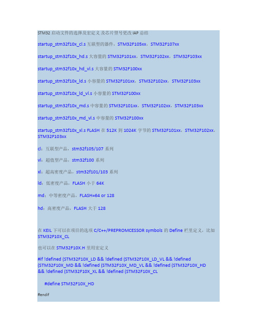
STM32启动文件的选择及宏定义及芯片型号更改 IAP总结startup_stm32f10x_cl.s 互联型的器件,STM32F105xx,STM32F107xxstartup_stm32f10x_hd.s 大容量的STM32F101xx,STM32F102xx,STM32F103xx startup_stm32f10x_hd_vl.s 大容量的STM32F100xxstartup_stm32f10x_ld.s 小容量的STM32F101xx,STM32F102xx,STM32F103xx startup_stm32f10x_ld_vl.s 小容量的STM32F100xxstartup_stm32f10x_md.s 中容量的STM32F101xx,STM32F102xx,STM32F103xx startup_stm32f10x_md_vl.s 中容量的STM32F100xxstartup_stm32f10x_xl.s FLASH在512K到1024K字节的STM32F101xx,STM32F102xx,STM32F103xxcl:互联型产品,stm32f105/107系列vl:超值型产品,stm32f100系列xl:超高密度产品,stm32f101/103系列ld:低密度产品,FLASH小于64Kmd:中等密度产品,FLASH=64 or 128hd:高密度产品,FLASH大于128在KEIL下可以在项目的选项C/C++/PREPROMCESSOR symbols的Define栏里定义,比如STM32F10X_CL也可以在STM32F10X.H里用宏定义#if !defined (STM32F10X_LD && !defined (STM32F10X_LD_VL && !defined (STM32F10X_MD && !defined (STM32F10X_MD_VL && !defined(STM32F10X_HD && !defined (STM32F10X_XL && !defined (STM32F10X_CL#define STM32F10X_HD#endif如果芯片更换,除了做如上所述的更改外,还需以下几步:第一步 system_stm32f10x.c的系统主频率,依实际情况修改#if defined (STM32F10X_LD_VL || (defined STM32F10X_MD_VL#define SYSCLK_FREQ_24MHz 24000000#else#define SYSCLK_FREQ_72MHz 72000000#endif另外外部时钟在文件:stm32f10x.h 依实际修改第二步定时器的参数依系统主时钟做适当修改第三步 flash地址misc.h中的NVIC_VectTab_Flash 0x08000000 要与KEIL选项target的IROM1的地址一致,如果是IAP程序,依ISP程序占用大小,APP的FLASH地址向后延,比如0X8002000,那么KEIL选项target的IROM1的地址也要就0x8002000,SIZE因为ISP占用了2000,所以就为0x40000-0x2000,即只能填写0X3E000第四步 ISP程序与APP程序连接----(这一步我还不明白意思,需要验证)打开 User 选项卡在 Run User Programs Before Build/Rebuild 中,勾选 Run#1,并在其中填入D:\Keil\ARM\BIN40\fromelf.exe --bin -o ./obj/Project.bin ./obj/Project.axf 其中,Project.bin 和 Project.axf 要和 Output 选项卡中的 Name of Executable 的名字IAP我的总结1 先FLASH_Unlock(;2 小于或等于128K的STM每页为1k bytes,大于128K的每页为2K BYTES,减去从地址0x8002000占用的0x2000后,算出页数,比如IAP占用8K,则64K的MD的STM32F系列用for(i=0;i<(64-8;i++ FLASH_ErasePage(0x8002000+0x400*i;循环按页擦除FLASH3 按从外部串口获取到的数据,FLASH_ProgramWord(address,dat;//注意是按4字节方式写入的 if (*(uint32_t*address!= dat//字编程后校验。
STM32固件库详解
STM32固件库详解1.1 基于标准外设库的软件开发1.1.2 使用标准外设库开发的优势简单的说,使用标准外设库进行开发最大的优势就在于可以使开发者不用深入了解底层硬件细节就可以灵活规范的使用每一个外设。
标准外设库覆盖了从GPIO到定时器,再到CAN、I2C、SPI、UART和ADC等等的所有标准外设。
对应的C源代码只是用了最基本的C编程的知识,所有代码经过严格测试,易于理解和使用,并且配有完整的文档,非常方便进行二次开发和应用。
1.1.3 STM32F10XXX标准外设库结构与文件描述1. 标准外设库的文件结构在上一小节中已经介绍了使用标准外设库的开发的优势,因此对标准外设库的熟悉程度直接影响到程序的编写,下面让我们来认识一下STM32F10XXX的标准外设库。
STM32F10XXX的标准外设库经历众多的更新目前已经更新到最新的3.5版本,开发环境中自带的标准外设库为2.0.3版本,本书中以比较稳定而且较新的V3.4版本为基础介绍标准外设库的结构。
可以从ST的官方网站下载到各种版本的标准外设库,首先看一下3.4版本标准外设库的文件结构,如图5-3所示。
3.0以上版本的文件结构大致相同,每个版本可能略有调整。
标准外设库的第一部分是CMSIS 和STM32F10x_StdPeriph_Driver,CMSIS 是独立于供应商的Cortex-M 处理器系列硬件抽象层,为芯片厂商和中间件供应商提供了简单的处理器软件接口,简化了软件复用工作,降低了Cortex-M 上操作系统的移植难度,并减少了新入门的微控制器开发者的学习曲线和新产品的上市时间。
STM32F10x_StdPeriph_Driver则包括了分别对应包括了所有外设对应驱动函数,这些驱动函数均使用C语言编写,并提供了统一的易于调用的函数接口,供开发者使用。
Project文件夹中则包括了ST官方的所有例程和基于不同编译器的项目模板,这些例程是学习和使用STM32的重要参考。
- 1、下载文档前请自行甄别文档内容的完整性,平台不提供额外的编辑、内容补充、找答案等附加服务。
- 2、"仅部分预览"的文档,不可在线预览部分如存在完整性等问题,可反馈申请退款(可完整预览的文档不适用该条件!)。
- 3、如文档侵犯您的权益,请联系客服反馈,我们会尽快为您处理(人工客服工作时间:9:00-18:30)。
STM32F102启动脚本分析stm3210e_flash.ld文件中重要的变量/* Entry Point */ENTRY(Reset_Handler) /*指定可执行文件的起始代码段为Reset_Handler *//* Highest address of the user mode stack */_estack = 0x20010000; /* end of 64K RAM *//* Generate a link error if heap and stack don't fit into RAM */_Min_Heap_Size = 64; /* required amount of heap */_Min_Stack_Size = 256; /* required amount of stack *//* Specify the memory areas */MEMORY{FLASH (rx) : ORIGIN = 0x08000000, LENGTH = 512KRAM (xrw) : ORIGIN = 0x20000000, LENGTH = 64KMEMORY_B1 (rx) : ORIGIN = 0x60000000, LENGTH = 0K}/* Define output sections */SECTIONS{/* The startup code goes first into FLASH */.isr_vector :{. = ALIGN(4); /*以4字节对齐*/KEEP(*(.isr_vector)) /* Startup code */ /*所有isr_vector的section都链接到此地址*/ . = ALIGN(4);} >FLASH/* The program code and other data goes into FLASH */.text :{. = ALIGN(4);*(.text) /* .text sections (code) */*(.text*) /* .text* sections (code) */*(.rodata) /* .rodata sections (constants, strings, etc.) */*(.rodata*) /* .rodata* sections (constants, strings, etc.) */*(.glue_7) /* glue arm to thumb code */*(.glue_7t) /* glue thumb to arm code */KEEP (*(.init))KEEP (*(.fini)). = ALIGN(4);_etext = .; /* define a global symbols at end of code */} >FLASH.ARM.extab : { *(.ARM.extab* .gnu.linkonce.armextab.*) } >FLASH.ARM : {__exidx_start = .;*(.ARM.exidx*)__exidx_end = .;} >FLASH.ARM.attributes : { *(.ARM.attributes) } > FLASH.preinit_array :{PROVIDE_HIDDEN (__preinit_array_start = .);KEEP (*(.preinit_array*))PROVIDE_HIDDEN (__preinit_array_end = .);} >FLASH.init_array :{PROVIDE_HIDDEN (__init_array_start = .);KEEP (*(SORT(.init_array.*)))KEEP (*(.init_array*))PROVIDE_HIDDEN (__init_array_end = .);} >FLASH.fini_array :{PROVIDE_HIDDEN (__fini_array_start = .);KEEP (*(.fini_array*))KEEP (*(SORT(.fini_array.*)))PROVIDE_HIDDEN (__fini_array_end = .);} >FLASH/* used by the startup to initialize data */_sidata = .;/* Initialized data sections goes into RAM, load LMA copy after code */.data : AT ( _sidata ) /*.data段,指定.data数据段的存储地址为当前的RAM地址*/ {. = ALIGN(4);_sdata = .; /* create a global symbol at data start */ /*data数据段的起始地址*/ *(.data) /* .data sections */ /*所有data数据段都链接到此地址*/*(.data*) /* .data* sections */. = ALIGN(4);_edata = .; /* define a global symbol at data end */ /*data数据段的结束地址*/ } >RAM/* Uninitialized data section */. = ALIGN(4);.bss : /*BSS栈段*/{/* This is used by the startup in order to initialize the .bss secion */_sbss = .; /* define a global symbol at bss start */ /*BSS栈的起始地址*/__bss_start__ = _sbss;*(.bss) /*所有bss栈段都链接到这里*/*(.bss*)*(COMMON). = ALIGN(4);_ebss = .; /* define a global symbol at bss end */ /*BSS栈的结束地址*/__bss_end__ = _ebss;} >RAMPROVIDE ( end = _ebss );PROVIDE ( _end = _ebss );/* User_heap_stack section, used to check that there is enough RAM left */._user_heap_stack : /*检查是否有建立堆段的足够空间*/. = ALIGN(4);. = . + _Min_Heap_Size;. = . + _Min_Stack_Size;. = ALIGN(4);} >RAM/* MEMORY_bank1 section, code must be located here explicitly *//* Example: extern int foo(void) __attribute__ ((section (".mb1text"))); */.memory_b1_text :{*(.mb1text) /* .mb1text sections (code) */*(.mb1text*) /* .mb1text* sections (code) */*(.mb1rodata) /* read-only data (constants) */*(.mb1rodata*)} >MEMORY_B1/* Remove information from the standard libraries *//DISCARD/ :{libc.a ( * )libm.a ( * )libgcc.a ( * )}}startup_stm32f10x_hd.S程序内容:1、初始化SP;2、初始化PC为Reset_Handler;3、设置向量表,用异常ISR地址进入;4、设置系统时钟,和外部SRAM,SRAM mount在EV AL开发板,并用于数据存储(用户可选);5、跳转到C库中的main函数。
.syntax unified.cpu cortex-m3.fpu softvfp.thumb.global g_pfnVectors.global Default_Handler/* start address for the initialization values of the .data section.defined in linker script */.word _sidata/* start address for the .data section. defined in linker script */.word _sdata/* end address for the .data section. defined in linker script */.word _edata/* start address for the .bss section. defined in linker script */.word _sbss/* end address for the .bss section. defined in linker script */.word _ebss/* stack used for SystemInit_ExtMemCtl; always internal RAM used */.equ BootRAM, 0xF1E0F85F* @brief This is the code that gets called when the processor first* starts execution following a reset event. Only the absolutely* necessary set is performed, after which the application* supplied main() routine is called.* @param None* @retval : None*/.section .text.Reset_Handler /*输入段描述符:text 和Reset_Handler */.weak Reset_Handler.type Reset_Handler, %functionReset_Handler:/* Copy the data segment initializers from flash to SRAM */movs r1, #0b LoopCopyDataInitCopyDataInit:ldr r3, =_sidataldr r3, [r3, r1]str r3, [r0, r1]adds r1, r1, #4LoopCopyDataInit:ldr r0, =_sdata /*从Flash中拷贝代码段_sdata和_edata 之间的代码到SRAM*/ ldr r3, =_edataadds r2, r0, r1cmp r2, r3bcc CopyDataInitldr r2, =_sbss /*BSS段清零*/b LoopFillZerobss/* Zero fill the bss segment. */FillZerobss:movs r3, #0str r3, [r2], #4LoopFillZerobss:ldr r3, = _ebsscmp r2, r3bcc FillZerobss/* Call the clock system intitialization function.*/bl SystemInit/* Call the application's entry point.*/bl mainbx lr.size Reset_Handler, .-Reset_Handler/*** @brief This is the code that gets called when the processor receives an* unexpected interrupt. This simply enters an infinite loop, preserving* the system state for examination by a debugger.* @param None* @retval None*/.section .text.Default_Handler,"ax",%progbitsDefault_Handler:Infinite_Loop:b Infinite_Loop.size Default_Handler, .-Default_Handler/****************************************************************************** ** The minimal vector table for a Cortex M3. Note that the proper constructs* must be placed on this to ensure that it ends up at physical address* 0x0000.0000.******************************************************************************** /.section .isr_vector,"a",%progbits /*输入段描述符:isr_vector */.type g_pfnVectors, %object.size g_pfnVectors, .-g_pfnVectorsg_pfnV ectors:.word _estack.word Reset_Handler.word NMI_Handler.word HardFault_Handler.word MemManage_Handler。